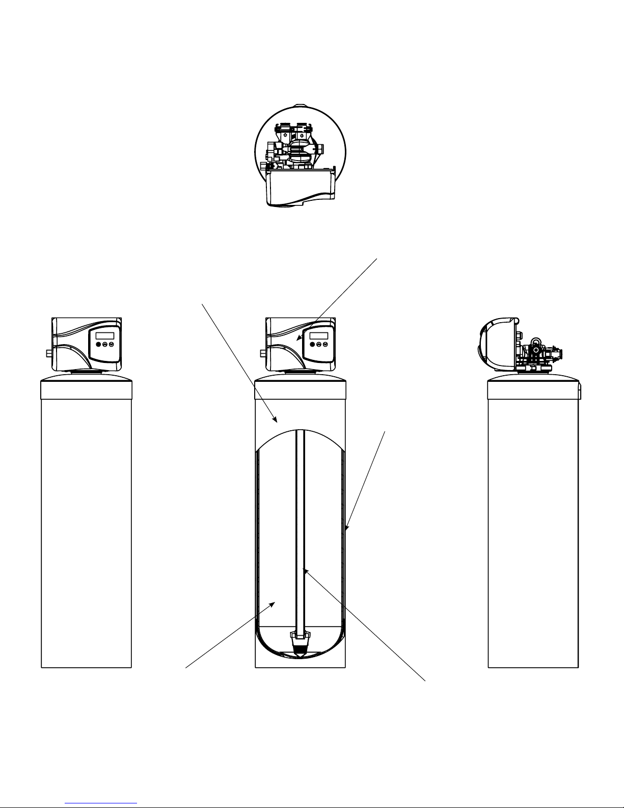
Duro 6200 SXT Service manual

6200 SXT Chemical Free Iron Filter
Operating and Service Manual
Made in Canada

1
Read this Manual First
• Read this manual thoroughly to become familiar with the device and its capabilities before installing or operating your
Water Filter. Failure to follow instructions in this manual could result in personal injury or property damage. This manual will
also help you to get the most out of your filter.
• This system and its installation must comply with state and local regulations. Check with your local public works depart-
ment for plumbing and sanitation codes. In the event the codes conflict with any content in this manual the local codes
should be followed. For installations in Massachusetts, Massachusetts Plumbing Code 248 CMR shall be adhered to. Con-
sult your licensed plumber for installation of this system.
• This water filter is designed to operate on pressures of 20 psig 125 psig. If the water pressure is higher than the maximum
use a pressure reducing valve in the water supply line to the softener.
• This unit is capable of operating at temperatures between 40°F and 110°F (4°C - 43°C). Do not use this water filter on hot
water supplies.
• Do not install this unit where it may be exposed to wet weather, direct sunlight, or temperatures outside of the range
specified above.
• Do not use water that is microbiologically unsafe without adequate disinfection before or after this system.
• This publication is based on information available when approved for printing. Continuing design refinement could cause
changes that may not be included in this publication. WaterGroup reserves the right to change the specifications referred
to in this literature at any time, without prior notice.
Safety Messages
Watch for the following safety messages in this manual:
NOTE: used to emphasize installation, operation or maintenance information which is important but does not
present a hazard.
Example: NOTE: Check and comply with you state and local codes. You must follow these guidelines.
CAUTION: used when failure to follow directions could result in damage to equipment or property.
Example:
CAUTION! Disassembly while under pressure can result in flooding.
WARNING: used to indicate a hazard which could cause injury or death if ignored.
Example:
WARNING! ELECTRICAL SHOCK HAZARD! UNPLUG THE UNIT BEFORE REMOVING THE COVER OR ACCESSING
ANY INTERNAL CONTROL PARTS
NOTE: Do not remove or destroy the serial number. It must be referenced on request for
warranty repair or replacement
Introduction

3
Specification
Working Temperature = 34-110°F (1-43°C)
(Do not subject the unit to freezing temperatures)
Working Pressure = 20-125 PSIG (137-861 kPa)
Voltage = 120V / 60 Hz
Pipe Size = 3/4”
• At the stated service flow rates, the pressure drop through these devices will
not exceed 15 psig.
• The manufacturer reserves the right to make product improvements which
may deviate from the specifications and descriptions stated herein, without
obligation to change previously manufactured products or to note the
change.
* Do not use water that is microbiologically unsafe without adequate
disinfection before or after the system.
† USA customers will need to add “-4” to the item numbers for ordering.
Peak flow rates intended for intermittent use only (10 minutes or less) and
are for residential applications only. Do not use peak flow rate for commercial
applications or for a continuous rate when treated water supplies are
geothermal heat pump, swimming pool, etc.
For satisfactory operation, the pumping rate of the well system must equal or
exceed indicated backwash flow rate.
All units come with plastic bypass
*Items include brine tank grid
Tank jackets are available on 8”, 9” and 10” diameter tanks
NC indicates cabinet model, NT indicates twin tank model
2
Unit
Item # Model # Tank Size
Media
(CF)
Service
Flow Rate
(gpm)
Peak
Service
Flow Rate
(gpm)
Back-
wash
Flow Rate
(gpm)
Shipping
Weight
(lbs)
Back-
Wash
Time
(Minutes)
Rapid
Rinse
(Minutes)
Total
Regenera-
tion Time
(Minutes)
Water used
during
Regeneration
(gallons)
4646 DIF75SXT 8 X 47 0.75 2 5 3.5 6 4 10 35 35
4647 DIF10SXT 9 X 48 1 3 6 4 6 4 10 40 70
4648 DIF15SXT 10 X 54 1.5 410 56410 50 80
4649 DIF20SXT 12 X 52 2 5 15 76410 70 100
4650 DIF15SXT-DH 10 X 54 (DH) 1.5 410 56410 50 40
4651 DIF20SXT-DH 12 X 52 (DH) 2 5 15 76410 70 50
4652 DIF75MSXT 8 X 47 0.75 2 5 3.5 6 4 10 35 70
4653 DIF10MSXT 9 X 48 1 3 6 4 6 4 10 40 100
4654 DIF15MSXT 10 X 54 1.5 410 56410 50 35
4655 DIF20MSXT 12 X 52 2 5 15 76410 70 40
4656 DIF15MSXT-DH 10 X 54 (DH) 1.5 410 56410 50 50
4657 DIF20MSXT-DH 12 X 52 (DH) 2 5 15 76410 70 70
Water and Time Consumed during regeneration
Unit
Item # Model # Tank Size
Media
(CF)
Service
Flow Rate
(gpm)
Peak Service
Flow Rate
(gpm)
Backwash
Flow Rate
(gpm)
Shipping
Weight
(lbs)
Chemical Free Iron Filters (IF)
4646 DIF75SXT 8 X 47 0.75 2 5 3.5 110
4647 DIF10SXT 9 X 48 1 3 6 4 145
4648 DIF15SXT 10 X 54 1.5 410 5 250
4649 DIF20SXT 12 X 52 2 5 15 7 365
4650 DIF15SXT-DH 10 X 54 (DH) 1.5 410 5 250
4651 DIF20SXT-DH 12 X 52 (DH) 2 5 15 7 365
Chemical Free Iron Filters Units (IF – M Models)
4652 DIF75MSXT 8 X 47 0.75 2 5 3.5 110
4653 DIF10MSXT 9 X 48 1 3 6 4 145
4654 DIF15MSXT 10 X 54 1.5 410 5 250
4655 DIF20MSXT 12 X 52 2 5 15 7 365
4656 DIF15MSXT-DH 10 X 54 (DH) 1.5 410 5 250
4657 DIF20MSXT-DH 12 X 52 (DH) 2 5 15 7 365

3
How a Duro Automatic Backwashing Filter Works
In normal operation, the Time of Day display will alternate being viewed with the Day Remaining display. As day passes,
the day remaining will count down from a maximum value to zero or (---). Once this occurs, a regeneration cycle will be
initiated at the Set Regeneration Time. Water flow through the valve is indicated by the Flow Indicator that will flash in direct
relationship to flow rate.
Example 3 Days Remaining
to Regenerate
0 Days Treated
Water Remaining
Timer Behavior During Regeneration
In regeneration, the control will display a special regeneration display. In this display, the control will show the current
regeneration step abbreviation the valve is advancing to or has reached and the time remaining in that step. The step
abbreviation displayed will flash until the valve has completed driving into this regeneration step position. Once all
regeneration steps have been completed, the valve will return to Service and resume normal operation.
Example Less than 6 minutes
remaining in Regeneration
Step Rapid Rinse
Pushing the during a regeneration cycle will immediately advance the valve to the next cycle step position and
resume normal step timing.
Please see the control valve manual for different regeneration step abbreviations.
PM Indicator
PM Indicator
Flow Indicator
(Flashing with water flow)
Flow Indicator
(Flashing with water flow)
5Regeneration Step
Abbreviation
The chemical free iron filter consists of two major components which are:
1. A hydrocharger, located between the well head and the pressure tank, adds a small amount of air to the iron-laden
water whenever the well pump runs. Refer to Figs. 1, 2 or 3 on Page 8 for its location.
NOTE: If your pump system is a constant pressure or variable frequency drive (VFD) the hydrocharger supplied with
this filter will not operate properly. The system will require the addition of an air pump and vent tank to intro-
duce the needed air into the water system. Refer to page 8 for more information.
2. A backwashing type filter containing special media that causes the iron in the “hydrocharged” water to precipitate
throughout the filter bed (rather than on the surface as in chemical oxidizing filters). This process produces an iron removal
capacity of up to 30,000 ppm. The media requires no chemical regenerant for oxygen enrichment. Your filter automati-
cally adjusts the pH to neutral or higher on acid water without an acid neutralizer. The ability to raise pH when it is below
neutral (7.0 or less) greatly enhances the filter’s ability to remove iron efficiently. The clean, filtered water then flows into
your household water line. Depending on water use and the concentration of iron in your water, periodic backwashing is
required to flush the entrapped iron from the system. The filter control can be programmed to backwash once every two,
three, four, six or twelve days as required (instructions for calculating backwash frequency and setting the controls are on
Pages 20 and 25).
NOTE: Replenishment of the media that raises pH will be required periodically, depending on how low the raw water
pH is, the amount of manganese (Mn) present in the water and the water usage rate.

5
4
Familiarize Yourself with the Unit and Components
Distributor/Riser
Media Bed
Tank Jacket
Tank
Control Valve

6
5
Installation Instructions
Contact your local distributor to use WaterGroup laboratory for complete water analysis free of cost
and no obligation to you.
All government codes and regulations governing the installation of these devices must be observed.
If the ground from the electrical panel or breaker box to the water meter or underground copper pipe is tied
to the copper water lines and these lines are cut during installation of the Noryl bypass valve and/or poly
pipe, an approved grounding strap must be used between the two lines that have been cut in order to main-
tain continuity. The length of the grounding strap will depend upon the number of units being installed and/or
the amount of copper pipe being replaced with plastic pipe. See Figure 1.
In all cases where metal pipe was originally used and is later interrupted by poly pipe or the Noryl bypass valve as in Figure
1 or by physical separation as in Figure 2, an approved ground clamp with no less than #6 copper conductor must be used
for continuity, to maintain proper metallic pipe bonding.
NOTE: Check your local electrical code for the correct clamp.
Before Installation
Inspecting and Handling Your Chemical Free Iron Filter
Inspect the equipment for any shipping damage. If damaged, notify the transportation company and request a damage
inspection. Damage to cartons should also be noted.
Handle the filter unit with care. Damage can result if it is dropped or set on sharp, uneven projections on the floor.
Do not turn the filter unit upside down.
NOTE: If a severe loss in water pressure is observed when the filter unit is initially placed in service, the filter tank
may have been laid on its side during transit. If this occurs, backwash the filter to “reclassify” the media.
iron (Fe)
Iron concentrations as low as 0.3 ppm will cause staining. The iron concentration, together with the flow rate demand and
the consumption rate of the water, determines the basic size of the filter system. The higher these factors are, the larger
the required system. The filter system is capable of filtering out the three main types of iron found in water supplies: soluble
iron (also known as “clear water” or ferrous iron), precipitated iron (also known as “red water” or ferric iron) and bacterial
iron (also known as iron bacteria). There is no apparent upper limit of iron concentration for the filter but special care must
be taken when selecting a filter model if your water has a combination of high iron, very low pH and/or manganese.
Manganese (Mn)
The presence of manganese can be bothersome, even for a chemical free iron filter. As little as 0.05 ppm of manganese
can produce a brownish or black stain. The ability of the filter to remove manganese depends on its concentration and
the pH of the water.
Manganese tends to “coat” the filter media, rendering it incapable of increasing the pH and, therefore, ineffective
in removing either the iron or the manganese. Manganese, however, will precipitate in the filter bed when the pH is
increased. To accomplish this, a special “M” type media that contains additional quantities of the pH raising component
(“MpH adder”) can be provided. The use of “M” type media is for applications where the manganese is not more than 1.5
ppm, and the pH is 6.0 or higher. When the pH is below 6.0, consult your dealer.

6
pH
The pH of water measures its acidity or its alkalinity. Water with a pH of less than 7.0 is acidic, above 7.0 is alkaline, and 7.0
is neutral. The lower the pH value is below 7.0, the greater the acidity and the higher the pH value is above 7.0, the more
alkaline. Acidic water (pH less than 7.0) is corrosive to pipes, appliances, etc. A pH of 7.0 or higher facilitates iron removal
— which is why the filter is designed to increase the pH when it is less than 7.0.
The pH increasing component of the media is “sacrificial”. That is, it slowly dissolves during the process of increasing pH.
The rate at which this occurs is proportional to the pH increase and the water consumption rate (i.e. the greater the pH
increase and the water consumption, the greater the sacrificial rate). Thus, when the pH is increased to 8.2 or more as
is necessary when manganese is present, the sacrificial rate is even greater. Under the most severe conditions, the MpH
component of the media may have to be replenished two to four times per year. On the other hand, if the raw water pH is
7.0 or above and no manganese is present, the sacrificial rate is very slight.
Tannins (Humic Acid)
Tannins (also known as humic acid), which are present in some supplies, are the result of decaying vegetable matter.
If the tannin concentration is above approximately 0.5 ppm, it will form a sticky coating on the media, thus rendering it
incapable of filtering the iron. A chemical free iron filter is not recommended for this situation. If the tannin concentration is
less than 0.5 ppm, a chemical free iron filter may be installed.
Hydrogen sulfide (h2s)
Hydrogen sulfide (often referred to as “sulfur”), is easily detectable by its objectionable “rotten egg” odor. Sulfur corrodes
iron, brass, copper and silver. A chemical free iron filter is not recommended when hydrogen sulfide is the only water
problem, although it is capable of removing sulfur in concentrations of up to 2 to 3 ppm. Whenever hydrogen sulfide is
present, backwashing must be performed at more frequent intervals and the pumping system MUST include a standard air-
to-water pressure tank with an air relief valve.
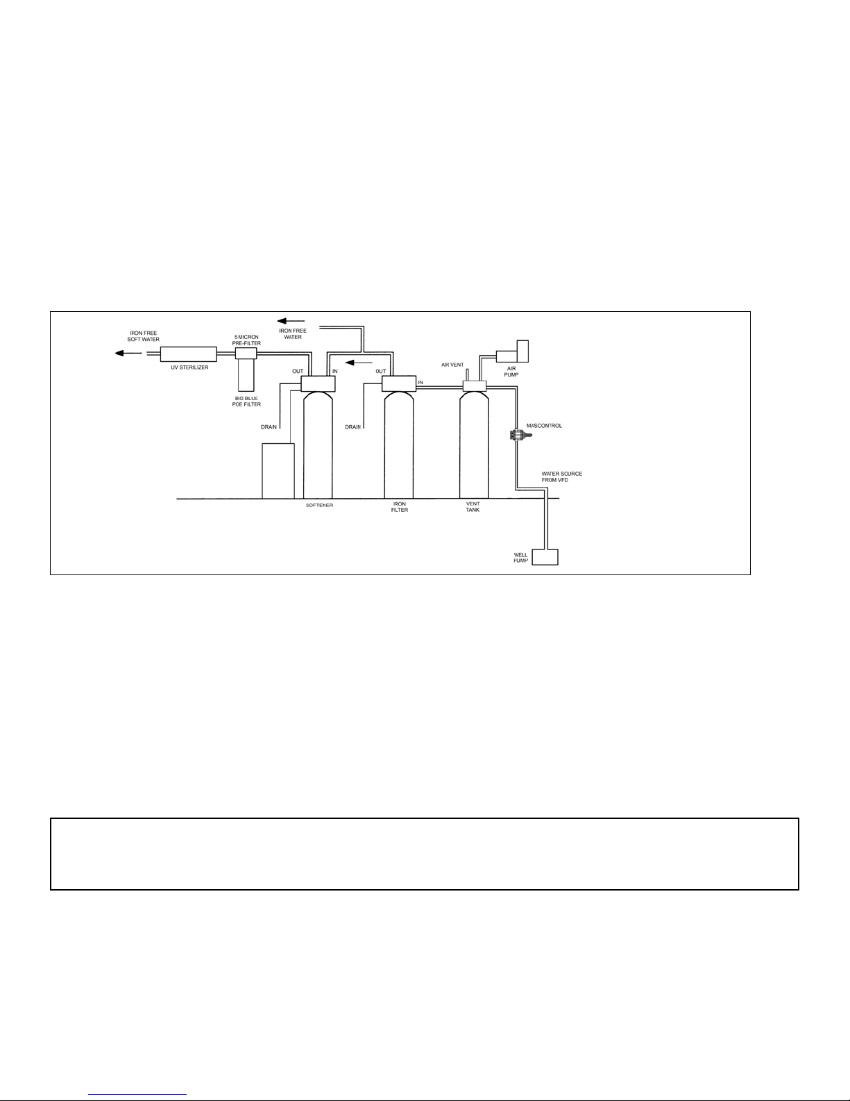
Check Your Water Pressure and Pumping Rate
Two water system conditions must be checked carefully to avoid unsatisfactory operation or equipment damage:
1. Minimum water pressure required at the filter tank inlet is 20 psi. If pressure is over 50 psi, a pressure reducing valve must
be installed in the water supply line ahead of the hydrocharger (Fig. 1, 2 or 3, Page 8).
2. The pumping rate of your well pump must be at least 5 gallons per minute (gpm) for satisfactory operation of
the hydrocharger. In addition, the pumping rate must equal the required backwash flow rate of your model (see
Specifications on Page 1 for backwash flow rates). To measure the pumping rate of your pump, follow these
instructions:
a. Make certain no water is being drawn. Open spigot nearest pressure tank. When pump starts, close spigot and
measure time (in seconds) to refill pressure tank (when pump shuts off). This figure represents cycle time.
b. With the pressure tank full, draw water into a container of known volume and measure the number of gallons drawn
until the pump starts again. This is draw-down. Divide this figure by cycle time and multiply the result by 60 to arrive at
the pumping rate in gallons per minute (gpm). To aid in your calculation, insert the data in the following formula:
DRAWDOWN________÷ CYCLE TIME______________x 60
(gals) (seconds)
= PUMPING RATE______________
(gpm)
EXAMPLE: DRAWDOWN is 6 gals; CYCLE TIME is 53 secs; then, PUMPING RATE equals:
6 gals ÷ 53 secs x 60 = 6.8 gpm
See Specifications on page 2 for minimum flow rates.
NOTE: If your pumping rate is inadequate, do not install your filter until the problem is solved.

8
Locate Water Conditioning Equipment Correctly
Select the location of your filter tank with care. Various conditions which contribute to proper location are as follows:
1. Locate as close as possible to the water supply source.
2. Locate as close as possible to a floor or laundry tub drain.
3. Locate in correct relationship to other water conditioning equipment (see Fig. 1, 2 or 3, Page 8).
4. Filters and softeners should be located in the supply line before the water heater. Temperatures above 120°F damage
filters and softeners and will void the factory warranty.
5. Do not install a filter or softener in a location where freezing temperatures occur. Freezing may cause permanent
damage to this type of equipment and will void the factory warranty.
6. Allow sufficient space around the unit for easy servicing.
7. If your water source is a community water supply, a public water supply or you wish to bypass water used for a
geothermal heat pump, lawn sprinkling, out-buildings or other high demand applications, refer to Fig. 2 or 3 on Page 8
for additional equipment required.
The Importance of Your Pressure Tank
The pressure tank found on private well systems becomes an integral part of the filter system by providing necessary
mixing and “contact time” to the “hydrocharged” water. While the iron filter will perform better on a standard air-to-water
pressure tank, it will perform satisfactorily on a captive air (bladder) pressure tank. The bladder tank requires more careful
adjustment of the hydrocharger and careful location of the air relief valve. (see page 17).
If cycle time on pumping system is less than 30 seconds and severe operating conditions exist (low pH, high iron,
manganese, and small concentrations of sulfur), a standard air-to-water pressure tank with an air-relief valve must be used
(if a bladder tank is already in place – do not remove it – install the air-to-water pressure tank between the hydrocharger
and the bladder tank).
NOTE: If your pressure tank (or any part of your water system) is not functioning properly, corrective action must be taken
before installation of your iron filter.
Facts to Remember When Planning Your Installation
1. All installation procedures must conform to local and state plumbing codes.
2. All water must pass through the hydrocharger, pressure tank and the filter, or refer to the special instructions for a split-
stream installation on Page 18. (System may malfunction if these instructions are ignored.)
3. If lawn sprinkling, a swimming pool, geothermal heating/cooling or water for other devices/activities is to be treated
by the filter, a larger model filter must be selected to accommodate the higher flow rate demands of these items. The
pumping rate of the well pump must be sufficient to accommodate these items plus the backwash requirement of the
filter. Consult your dealer for alternative instructions if the pumping rate is insufficient.
4. Remember that the filter inlet is attached to the pipe that supplies water (i.e., runs to the pump) and the outlet is the line
that runs toward the water heater.
5. Before commencing installation, it is advisable to study the existing piping system and determine the size, number
and type of fittings required. Typical system schematics shown in these instructions (Fig. 1, 2, or 3, Page 8), will be of
assistance.
NOTE: If the plumbing system is used as the ground leg of the electric supply, continuity should be maintained by
installing ground straps around any nonconductive plastic piping used in installation.
6. When utilizing a constant pressure or VFD pump system you will require the addition of an air pump and vent tank kit
#978003 for 115 volt or 978004 for 230 volt systems. A flow switch #79980 will also be required to run the air pump, see
Figure 4 on page 9 for installation diagram.
7

9
Proper installation sequence of water conditioning equipment is very important. Refer to the diagrams following for your
particular water supply.
NOTE: The Braukman air vent is not approved for use in the State of Wisconsin. An approved air to water tank and/or air
vent should be used with this application in the State of Wisconsin.
NOTE: Before starting installation, read page 18, Plumbing System Clean-Up, for instructions on some procedures that
may need to be performed first.
Figure 1
Figure 2
Figure 3
Installation
8

10
1. Determine the best location for your water filter, bearing in mind the location of your water supply lines, drain line and 120
volt AC electrical outlet. Subjecting the filter to freezing or temperatures above 43°C (110°F) will void the warranty.
2. Cut main supply line as required to fit hydrocharger in plumbing between well pump and pressure tank (hydrocharger
may be installed in a vertical or horizontal position). Allow a minimum of 6 inches straight run of pipe on each side of
hydrocharger, excluding fittings. Be certain direction of flow arrow on hydrocharger points toward pressure tank, and
pressure control switch is located on pressure tank side of the hydrocharger as in Fig. 1, 2 or 3, (rapid cycling of pump may
occur if pressure switch is located on well side. If check valves are used, they should be installed before the hydrocharger
– not between the hydrocharger and pressure tank).
NOTE: It is advisable to install the hydrocharger with the unions at both ends to facilitate removal and inspection. If
heat is applied near hydrocharger, remove rubber check valve to prevent damaging it. On badly scaled, older
pumping systems, it may be advantageous to install an optional “Y”-strainer ahead of hydrocharger to prevent
plugging hydrocharger nozzle with scale.
Installation of the Air Pump with Flow Control Switch (Mascontrol) as Power Source
1. Used when pressure switch and air pump are in alternate locations. Also used on constant pressure or variable speed
pump systems.
2. Mascontrol acts as a flow control detecting flow.
3. Connect the air pump to the Mascontrol receptacle. See Mascontrol manual for wiring diagram.
4. All government codes and regulations governing the installation of these devices must be observed. Check your local
electrical codes or contact a qualified electrician.
Figure 4
9

11
Figure 2
Filtered Water Line in Home
Unfiltered Water Bypass
Loop Cut & Capped
Ground Strap Required
Because of Break in Continuity
1. Media Installation (When Necessary). Models including and higher than 1.5 CF of media are shipped with separate
media in pails or boxes. Models lower than 1.5 CF of media come loaded with media and this step can be skipped for
new installation.
10
a) Remove the valve from
the mineral tank.
b) Temporarily plug the open end
of the riser tube to ensure that no
resin or gravel falls down into the
distribution.
The riser (distributor) remains
inside the tank seated in the
depression at the bottom.
Plug tube with a tape.
Remove after media is loaded.
Fill support bed first. (if supplied)
The media will not always spill down
inside the tank and may need to be
swept inside.
e
D
C
B
Plug
the
Riser
Tube
a
b
e
The riser
(distributor)
remains inside
the tank seated
in the depression
at the bottom
Preparations
CAUTION! The unit should be de-pressurized before installing or replacing media

12
c. Fill mineral tank one quarter full of
water to protect distribution during
gravel installation.
d. Place the media into the tank in the
order indicated above. Slowly and
carefully add the gravel support
bed and the softener or filtration
media leveling each layer as it is
placed into the tank.
e. Fill support bed (if supplied) first.
During the filling process, ensure the
distributor tube stays on the bottom
of the tank, reasonably centered.
Remove the tape from the distribu-
tor once media is loaded. Whenever
possible, fill the tank outdoors to
avoid problems with dust. If filling
indoors, a dust mask should be worn.
f. Unplug the riser tube, carefully position the valve over it and turn the valve into
the threads in the fiberglass tank, tightening securely into tank. Note: Ensure
that the internal O-ring in the valve fits securely over the riser tube. Silicone
grease (part # 92360) or other food grade lubricant may be applied to the O-
ring to ease installation of the riser tube.
The large funnel (sold separately part
# 43000) makes filling the tank easier
and neater. (Or an empty 1 gallon or 4
liter container with the bottom cut out
makes a good funnel.)
O-ring
D
C
B
ff
11
NOTE: Some medias like used in Chemical Free Iron Filter are sacrificial and deplete faster depending on inlet
water conditions and usage. The media replenishment is more frequent in high water usage and more
acidic water cases.
A dome hole models are available and supplied in which the dome hole is available for a quick addi-
tion or replenishment of media in the tank
Calcium
Carbonate &
Magnesium
Oxide
Mixed
(Grey / White)
Sand Filter
Support Bed
(when supplied)
Fine, Medium
and/or Coarse
Gravel

13
f
DO NOT use petroleum based lubricants as they will cause swelling of O-ring seals.
Dome Hole
Cap
Dome Hole Cap
Removed.
CAUTION: make sure the O-Ring is free of
defects. Use silicone based lubrication
(part # 92360) if neccesary
12
The filter is now charged with media.
g. It is recommended that the softener or filter tank now be completely filled with water (SLOWLY) to soak the resin or filtra-
tion media before startup. This will allow the media to absorb water as well as help displace any trapped air. This will
reduce the chance of backwashing resin or filter media out of the tank during the initial backwash on startup.
3. Outside faucets used to water lawns and gardens should not supply softened water. A new water line is often required to
be connected to supply hard water to the inlet of the water softener and to the outside faucets.
Cut the water line between where it enters the house and before any lines that branch off to feed the hot water heater
or other fixtures in the house and as near the desired location of the water softener as possible. Install a tee fitting on
the feed end of the cut pipe, and an elbow fitting on the other end. Install piping from the tee to the inlet of the water
softener and from the elbow to the outlet of the softener. To sever the water lines which branch off to feed any outside
faucets, cut the branch lines approximately two inches from the fitting on the main water line. Install an elbow on the
end of the pipe nearest the outside faucet and a cap on the end connected to the existing water line. Install piping from
the tee installed on the inlet line to the water softener to the elbow installed on the pipe to the outside faucet. Following
this procedure will result in all lines in the house, with the exception of the outside faucets, but including the water heater
and therefore the hot water lines, being supplied with soft water.
CAUTION! Make sure that the unit is de-pressurized before
conducting this task.

14
13
2. Familiarize yourself with the location
of the inlet, outlet and drain on the
control valve. Be very careful not to
get the controls wet.
3. Familiarize yourself with the buttons
on the timer control.
Drain 1/2”
Inlet
Outlet
2
Timer Controls
DOWN
button
UP button
Extra Cycle
Button
3
1. Clamp Ring – The clamp ring con-
nects the control valve to the tank
and provide an easy way to discon-
nect tank during control valve servic-
ing. Make sure that the clamp ring
screw is tightened.
The “Clamp Ring” should secure the valve with the top of the flange
facing up. Please note “top” on the clamp ring.
1
Installation Steps:

15
14
Do not use pipe thread
compound as it may
attack the material in
the valve body
.
Yoke
Bypass
Make sure that the flow
meter is connected to the
outlet of the valve.
Flow meter installation is
optional. The flow meter is
not supplied with the filter.
4
4. Attach the bypass valve to the con-
trol valve (and yoke if plastic bypass
is used). Connect the inlet and outlet
of the water softener to the plumb-
ing in the house. The control valve
must not be submitted to tempera-
tures above 43°C (110°F). When
sweat fittings are used, to avoid
damaging the control valve, solder
the threaded copper adapters to
the copper pipe and then, using
Teflon tape, screw the assembly into
the bypass valve.
Waste connections or drain outlet shall be designed and constructed to provide for connection to the sanitary
waste system through an air-gap of 2 pipe diameters or 1 inch (22 mm) whichever is larger.
Never insert drain line directly into a drain, sewer line, or trap. Always allow an air gap between the drain line and
the wastewater to prevent the possibility of sewage being back-siphoned into the conditioner.
5. Drain Line Connection: Using teflon
tape, screw the 1/2” hose barb into
the drain port in the valve. Attach
1/2” drain hose to the hose barb and
tighten securely with a hose clamp.
Run the drain line to a floor drain or a
laundry drain. Complete any neces-
sary plumbing.
Hose Barb
Connect 1/2”
drain hose (not supplied)
with a hose clamp here
5
5
5

16
6. Make sure the bypass valve is in the
service position.
7. Plug the 24-volt transformer into a
120 VAC 60 Hz outlet.
8. This valve has two positions: 1)
Backwash and 2) Rapid Rinse. When
the valve is in the Service position
must be pressed and held for
5 seconds before it activates. Press
and hold the pic for 5 seconds
to advance the valve into the “1”
Backwash position. Press once more
to advance to the “2” position.
outlet
intlet
Circuit Board Screen
Brine Cam
Position Label
15
Cycle Step Abbreviation
BW Backwash
RR Rapid Rinse
SV Service
The valve position during regenera-
tion and servicing can be checked
in the circuit board screen as well
the position label on the cam.
6
7
8

17
IMPORTANT: The filter should be backwashed for 15 minutes
before using this for first time. During initial backwashings, a
small amount of fine white media may be observed in the
drain water.
7
Hard Water Soft Water
To Drain
Hard Water Soft Water
To Drain
Hard Water Soft Water
To Drain
Service Position Backwash Position
To Drain
To Drain
Filtered Water
Filtered Water
Raw Water Raw Water
16
9. Press to advance the valve to the “1” Backwash po-
sition. Slowly turn on the water supply and allow the unit to
backwash until the air purges out of the tank and clears
the system.
IMPORTANT NOTE: Automatic water filters are supplied
from the factory in the backwash position, ready for start
up. Turn on the water supply to the unit. Open the supply
line slowly and allow the air to escape from the filter
before turning the supply water on all the way. Allow the
unit to backwash until all the air and media fines are no
longer showing at the drain. This may take up to 15 min-
utes so you need to unplug the timer until you are ready
to continue.
10. Press once more to advance to the “2” Rapid Rinse
position and allow water to run to drain for 2 Minutes.
Water Conditioner Flow Diagrams
Hard Water Soft Water
To Drain
Hard Water Soft Water
To Drain
Hard Water Soft Water
To Drain
BW
10
Rapid Rinse Position
RR
10
11. Press to advance the valve back into the service
position indicated by the
in upper left corner of
the display.
12. Set time of the day in the control valve and program the
user section of the control. Refer to control valve pro-
gramming section in this manual.
NOTE: ALL STATE AND LOCAL GOVERNMENT CODES GOVERNING INSTALLATION OF THESE DEVICES MUST BE OBSERVED.
Filtered Water
Raw Water
NOTE: After start-up, this filter may take several days to
completely remove the iron. This is normal be-
cause of the nature of the media.

18
1.AirReleaseCapmustbelooseorremovedtoallowairtoescapefromvent.
2.VentBushing1/2”x1/8”
3.Toopeningonsideofretentiontank(approximately1/2wayup,frombottomoftank)
4.3/4”x3/4”x1/2”coppertee
5.3/4”adapterwithbushingtotank
NOTE: The Braukman air vent is not approved for use in the State of Wisconsin. An approved air to water tank and/or air
vent should be used with this application in the State of Wisconsin.
The Braukman Air Vent must be installed at the highest point of the plumbing, between the pressure tank and filter (see
Fig. 7). Please note that the Braukman Air Vent (A) is mounted on a four to six inch pipe extension (B) at the elbow (C) of
the highest point. This enables the vent to better collect any excess air created by the hydrocharger.
To use the Braukman Air Vent on an air-to-water pressure tank, install it approximately halfway up the side of the tank, as
shown in the detailed drawing below.
open
closed
1
2
4
3
Figure7A Figure7B
A
Braukman
Air Vent
Braukman
Air Vent
Pressure
Tank
(Diaphragm)
Pressure
Tank
(Air to
Water)
See
Figure 8
B
C
A
B
C
Out InOut In
5
Figure8
Braukman Air Vent Installation
Set hydrocharger by following these steps:
A. Open nearest faucet until pump starts, then close faucet.
B. Place a finger over suction port (Fig. 6) A slight suction should be detected
for a minimum of 20 seconds or for approximately one-third of pumping cycle
whichever is greater.
C. If suction duration is too short, increase by turning water flow adjusting screw
(Fig. 6) clockwise. To decrease duration, turn counterclockwise.
D. Repeat Steps A through C until proper setting is obtained. When the duration
of the suction is too long, cold water may have a “milky” appearance caused
by excess air in system. Correct this condition by reducing the duration of suc-
tion. This condition is one commonly associated with bladder-type pressure
tanks. In extreme cases excess air prevents the system from performing satis-
factorily, consequently it is essential to install an air relief valve (such as a
Braukman) in the proper location.
17
Figure 6
Air Suction Port
Screw to adjust
flow rate

19
The following procedures are guidelines only but have proven successful in most instances. Under no circumstances
should any procedure outlined below be followed if contrary to the appliance manufacturer’s instructions. Should there
by any questions concerning the advisability of performing a procedure, it is strongly recommended the manufacturer’s
authorized service outlet be consulted prior to performing the procedure.
The plumbing system and water using appliances that have been exposed, even for a short time, to iron-fouled water
need to be cleaned of the precipitated iron that has collected in them or iron bleed (staining) will continue to be a
problem.
Depending on the amount of iron in the water and the length of time the water system has been exposed to iron fouling,
select from the following procedures those that apply to the type of system and appliances that need to be cleaned to
assure iron-free water at the point of use.
Softener
It isn’t uncommon that a softener was installed in an effort to remove ferrous (“clear water”) iron from the water supply.
Typically, a softener will remove some ferrous iron until the resin bed becomes fouled to the extent that it will lose both
hardness removal capacity and the limited capacity for iron removal. This is the condition to expect a softener to be in
when planning a system clean-up.
Prior to closing main supply valve or turning power off to a private well system and preparatory to installing the filter system,
do the following:
1. Disconnect brine draw line from the brine cabinet and place the loose end into a five gallon plastic pail filled with a
solution of warm water and 4 oz. of resin mineral cleaner.
2. Manually advance control timer to brine draw position (refer to instructions provided with your softener). Allow all the
warm mineral cleaner solution to be drawn into mineral bed. Then immediately:
3. Close main water supply valve or turn power off to pump and proceed with filter installation. During time required to
install filter system, iron-fouled softener resin will be chemically cleaned.
4. After filter installation is completed and final adjustments are made with the water turned on and brine draw tube
reconnected, manually reposition timer on softener to backwash position. Allow timer to perform an automatic
regeneration cycle. During backwash of softener, all iron cleaned from the resin will be washed down the drain. It is
advisable, after chemically cleaning softener, to regenerate system twice to fully restore capacity lost due to iron fouling.
Plumbing System Clean-Up
Special Instructions for Split-Stream and Public Water Supply Type Installations:
For a split-stream installation, a secondary pressure tank must be installed as in Fig. 2. On a public water supply installation,
a pressure tank must be installed as in Fig. 3, Page 8.
1. Install pressure tank (secondary pressure tank in Fig. 2, Page 8) as indicated by appropriate diagram.
2. Install normally-closed solenoid valve after water meter and after a line split for untreated water (if there is one).
3. On both types of installation, install the hydrocharger between pressure tank (secondary pressure tank on split-stream
type installations) and normally-closed solenoid valve.
4. Install a pressure switch after the hydrocharger and wire it to the solenoid valve (secondary pressure switch on split-
stream). Set high pressure on pressure switch (which controls opening and closing of solenoid valve) to 3 psi lower than
low pressure on primary pressure switch. Example: if primary pressure switch is set at 40 to 60 psi, set secondary pressure
switch high at 37 to 38 psi.
For public water supply installations, contact your local water department or plant operator and ask what the normal
low system pressure is. Set high pressure on pressure switch 2 to 3 psi lower than this figure.
NOTE: Failure to set the pressure switch as described above will not allow proper closing of the solenoid valve during
periods of low system pressure.
18

20
19
More than 90% of problems affecting the efficiency of a chemical iron free filter system can be identified in 9 minutes or
less by following this diagnostic schedule. Start with Step 1, then follow each step in sequence to ensure proper diagnostic
procedures.
1. Check for Proper Installation
a. Is the hydrocharger installed between well pump and pressure tank with arrow pointing toward pressure tank?
b. Is there a minimum of 6 inches on the hydrocharger inlet and 6 inches on the outlet of the straight pipe, free of pipe
fittings?
c. Is the check valve (if used) correctly located between the pump and the hydrocharger?
d. Is the pipe from the pressure tank to the filter unit attached to the inlet port of the control valve?
Is the pipe from the filter unit to the water heater attached to the outlet port of the control valve?
e. Is the drain line of adequate diameter? Drain line must be sized to prevent back pressure from reducing backwash
frow rate below minimum for the model installed. Typical examples of minimum drain line diameters are:
i) 1/2” ID when drain is up to 15 ft from unit and backwash discharge point is lower than the control valve
ii) 5/8” ID when drain is up to 15 ft from unit and backwash water discharge point is slightly higher than the control
valve
iii) 3/4” ID when drain is 25 ft away and/or drain is installed overhead
f. Has the drain line been “kinked”? A kinked drain line must be replaced.
g. Is the drain line installed in a way that it will freeze in cold weather?
h. If the system incorporates a standard air-to-water pressure tank, does it have the required deep well air volume
control (air release valve) and is it functioning? (Proper installation of this type of pressure tank should have inlet
from pump higher than outlet to service.)
2. Check pH, Iron and Manganese Content of Treated Water
Is the treated water pH reading less than 6.7 (8.2 when manganese is present)? If yes, replenish the media with MpH
adder and check the bed for “channelling”.
3. Check Pumping Rate
Do not refer to a pumping rate curve for this data. Follow the instructions found on Page 7. Is the measured pumping
rate less than the backwash rate of the filter? If yes, increase the pumping rate by first reducing the system operating
pressure. If the pumping rate is still too low, replace the pump.
4. Check Hydrocharger for Proper Air Draw
Does air suction continue for 1/3 of the time the pump runs (do not confuse with 1/3 of the pressure range)? Turn the
water flow adjusting screw clockwise to increase the draw time and counter-clockwise to decrease the draw time.
5. Manually Stage Filter Control to Backwash Cycle
Does a “rush” of air precede the backwash water out of the drain line? (If no, proceed to Step 6). If yes, the system is
“air-logged”. Disconnect power from the pump and allow the system pressure to drop to zero through the filter drain
line. Restore power and rebuild system pressure. Continue backwashing unit until the pump has completed two or three
pressure cycles. Stage control valve to the service position and check the hydrocharger draw time. Adjust draw for 1/3
of pump cycle time.
6. Determine Other Uses of Water in Addition to Normal Domestic Purposes
(e.g. geothermal heating or cooling, swimming pool fill, lawn irrigation, farm animal watering, etc.) Have any high
demand water uses been added subsequent to the installation of the filter system or overlooked when originally sizing
the system? (If a high demand situation exists, resize the system using continuous service flow rate data.)
System Check List
Other manuals for 6200 SXT
1
Table of contents
Other Duro Water Filtration System manuals
Popular Water Filtration System manuals by other brands

Clean Water
Clean Water 7500-REV4 installation guide

STIEBEL ELTRON
STIEBEL ELTRON FOUNTAIN 7S user manual

V-Guard
V-Guard ZENORA Series Operating Manual & Warranty Guide

Aqua Guard
Aqua Guard Invisipure user manual

Waterco
Waterco HYDROCHLOR ST owner's manual

US Water Systems
US Water Systems Matrixx 150-FLCS Series owner's manual

EHEIM
EHEIM Professionel-3 2080 operating instructions

Graco
Graco 17L366 Safety instruction

EM-Technik
EM-Technik 7F400 Assembly and operation instructions

DeVilbiss
DeVilbiss 130524 Replacement

Vulcan-Hart
Vulcan-Hart SCALEBLOCKER SPS600V Installation & operation manual

Oase
Oase FiltoSmart 60 operating instructions