DV Power TRT03 User manual

TRT03
THREE-PHASE TRANSFORMER
TURNS-RATIO TEST INSTRUMENT
Manual

TRT03 Contents
M-T003NN-205-EN 2
Contents
1 Introduction...........................................................................................................................................3
1.1 Safety Instructions.............................................................................................................................3
1.1.1 Safety Terms and Symbols........................................................................................................3
1.1.2 Terms of Use.............................................................................................................................3
1.1.3 Orderly Practices and Procedures.............................................................................................4
1.1.4 Instrument Maintenance............................................................................................................4
1.1.5 Operator Qualifications..............................................................................................................4
1.1.6 Safe Operating Procedures .......................................................................................................4
1.2 Power Supply....................................................................................................................................5
1.3 Measurement Category.....................................................................................................................5
1.4 Intended Use.....................................................................................................................................5
2 Description............................................................................................................................................6
2.1 Front Panel Components...................................................................................................................6
3 Getting Started......................................................................................................................................8
3.1 Connecting TRT03 to a Test Object..................................................................................................8
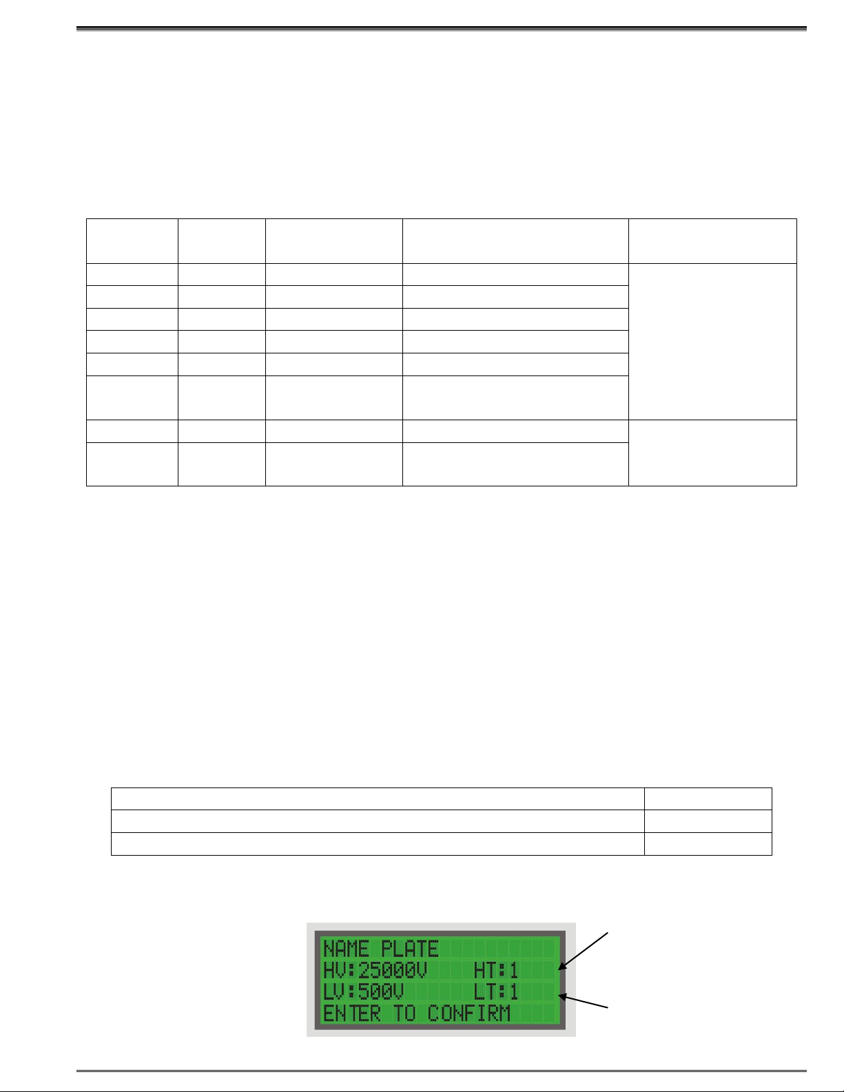
3.2 Setting the Measurement Parameters...............................................................................................9
4 Error Messages...................................................................................................................................12
4.1 Error Message “Excitation current too high”.....................................................................................12
4.2 Error Message “Turns ratio too low” ................................................................................................12
4.3 Error Message “Malfunction” ...........................................................................................................12
4.4 Error Message “Error printer”...........................................................................................................12
4.5 Error Message “Check paper” .........................................................................................................13
4.6 Error Message “USB flash drive” .....................................................................................................13
4.7 Error Message “Emergency Stop” ...................................................................................................13
4.8 Error Message “Connections”..........................................................................................................13
5 Troubleshooting Guide........................................................................................................................14
6 Customer Service................................................................................................................................15
7 Packing the Instrument for Shipment...................................................................................................15
8 Technical Data....................................................................................................................................16
8.1 Mains Power Supply........................................................................................................................16
8.2 Output data .....................................................................................................................................16
8.3 Measurement..................................................................................................................................16
8.4 Environmental conditions ................................................................................................................16
8.5 Dimensions and Weight...................................................................................................................16
8.6 Applicable Standards ......................................................................................................................17
9 Accessories.........................................................................................................................................18
Manufacturer Contact Information...............................................................................................................19
Manual Version: M-T003NN-205-EN
This Manual refers to the following TRT03 models and their corresponding firmware versions
Model
Firmware versions
TRT03A
TR0A-3.08
TRT03B
TR0B-3.08
TRT03C
TR0C-3.08

TRT03 Introduction
M-T003NN-205-EN 3
1 Introduction
The purpose of this Manual is to provide helpful instructions on how to use TRT03 instrument safely,
properly and efficiently.
The following instructions will help the user avoid unsafe situations, reduce maintenance costs and will
ensure the reliability and durability of TRT03 instrument.
TRT03 must be used in accordance with all existing safety requirements and regulations based on
national/local standards for accident prevention and environmental protection. In addition, the relevant
international standards are listed in paragraph 8.6 of the “Technical Data” section of this document.
1.1 Safety Instructions
Safety is the responsibility of the user. Before operating TRT03, please read the following safety instructions
carefully.
It is not recommended that TRT03 is used (or even turned on) without careful observation of the instructions
listed in this Manual. TRT03 should only be operated by trained and authorized personnel.
1.1.1 Safety Terms and Symbols
Terms in this Manual
These terms may appear in the Manual:
WARNING: Warning statements identify conditions or practices that could result in injury or loss of life.
CAUTION: Caution statements identify conditions or practices that could result in damage to this product or
to other property.
Terms on the Device
The following warning terms used in this document may appear on the device:
WARNING: indicates that potential hazard may occur.
CAUTION: indicates that potential damage may occur to the instrument or to the test object connected to
the instrument.
Symbols on the Device
The following symbols may appear on the device:
Refer to Protective
Manual Earth Terminal
1.1.2 Terms of Use
•TRT03 shall be used only if it is in good technical condition. Its use shall be in accordance with local
safety and industrial regulations. Adequate precautions must be taken to avoid any risks related to high
voltages associated with this equipment and nearby objects.
•TRT03 shall be used only for the application purposes described in the ”Intended Use” section. The
manufacturer and distributors are not liable for damage resulting from wrong usage. The user bears
responsibility for not following the instructions defined in this document.
•Do not remove the protective casing of TRT03.
•All service and maintenance work must be performed by qualified personnel only.

TRT03 Introduction
M-T003NN-205-EN 4
1.1.3 Orderly Practices and Procedures
•The Manual shall always be available on the site where TRT03 is used.
•Before using TRT03, all personnel (even personnel who only occasionally, or less frequently, work with
TRT03) assigned to operate TRT03 should read the operations Manual.
•Do not make any modifications, extensions, or adaptations to TRT03.
•Use TRT03 only with the original accessories provided by the manufacturer.
•Use TRT03 and its original accessories for the device’s intended use only.
1.1.4 Instrument Maintenance
The device should be kept clean in order to prevent excessive cases of dust or other contaminants affecting
its operation. It should be cleaned with water/isopropyl alcohol after any dirt/contaminants are noticed on its
surfaces.
1.1.5 Operator Qualifications
•Testing with TRT03 should only be carried out by authorized and qualified personnel.
•Personnel receiving any training or instructions on TRT03 should remain under constant supervision of
an experienced operator while working with the test set and the test object.
1.1.6 Safe Operating Procedures
•Hazardous voltages of up to 400 V can occur inside TRT03. Therefore, it is not permitted to remove the
protective casing of TRT03.
•Hazardous voltages exist on the terminals of TRT03 when the “Red”LED is lit. Never assume
connections are safe even if this LED is off. Switch off and unplug TRT03 before touching connections,
particularly if a fault is suspected.
•Before putting TRT03 into operation, check the test set for any visible damage.
•Do not operate TRT03 under wet or moist conditions (condensation).
•Do not operate TRT03 if explosive gas or vapors are present.
•Only external devices that meet the requirements for SELV equipment according to EN 60950 or IEC
60950 should be connected to TRT03 through the serial interface.
•Removing theTRT03 protective casing will void the warranty. Any work inside the instrument without
prior authorization from DV Power will also void the warranty.
•If TRT03 seems to be malfunctioning, please contact the DV Power Support Team (refer to the
“Manufacturer Contact Information” section) after previously checking the “Error Messages” section.
•Prior to connecting TRT03, ensure that a transformer (object) to be tested is completely de-energized
and isolated from both the line and the load. Every terminal should be checked and verified before
connecting TRT03. Ground connections may be left in place.
•Do not use TRT03 without the extra protective ground cables supplied with TRT03. It must never be
operated in a non-grounded configuration as this may result in an electrical shock to the user or damage
to TRT03. Always establish this connection first before establishing any other connections and remove
this connection as the very last one.
•Wherever possible, the outer casing of the transformer under test should also be connected to a safety
earth to prevent the risk of shock. Where this cannot be achieved, adequate precautions should be
taken to prevent access to the transformer (e.g. barriers).
•Never exchange connections to the HV and LV sides of the transformer. The “H”connections must
always be connected to the High Voltage side of the transformer. The “X”connections must always be
connected to the Low Voltage side of the transformer. Interchanging any or all of the connections may
result in damage to the transformer or TRT03 and is a significant safety hazard to personnel.

TRT03 Introduction
M-T003NN-205-EN 5
1.2 Power Supply
•Supply TRT03 only from a power outlet equipped with a protective ground.
•Besides supplying TRT03 from phase –neutral (L1-N, A-N), it may also be supplied from phase to
phase (e.g., L1-L2; A-B). However, the voltage must not exceed 264 V AC. Please refer to the section
“Technical Data”.
•TRT03 should be positioned in such a way that it is possible to safely disconnect it from the power
supply at any moment.
WARNING / AVERTISSEMENT
This is a class A product. In a domestic environment this product may cause radio interference in which
case the user may be required to take adequate measures.
Il s'agit d'un produit de classe A. Dans un environnement domestique, ce produit peut provoquer des
interférences radio, auquel cas l'utilisateur peut être amené à prendre des mesures adéquates.
1.3 Measurement Category
TRT03 is intended to be used for measurements in Measurement Category I (CAT I) for voltages up to
250V. The device is also designed to withstand occasional transient overvoltage up to 1000Vpk.
WARNING / AVERTISSEMENT
This equipment is classified as measurement category I, and must not be used within measurement
category II, III and IV.
Cet équipement est classée dans la I catégorie de mesure, et ne doit pas être utilisé pendant les
catégories de mesure II ,III et IV.
1.4 Intended Use
The Three-phase Transformer Turns Ratio Tester TRT03 is designed specifically for performing
measurements on power, distribution and measurement transformers as follows:
•turns ratio measurement
•phase shift measurement
•excitation current measurement
These three tests are performed at the same time. TRT03 applies test voltage to HV transformer terminals
and measures induced voltage at LV transformer terminals. The ratio of these voltages is actually the turns
ratio of a transformer. At the same time, TRT03 measures the excitation current at the HV transformer side,
as well as the phase angle between the applied test voltage and induced voltage.
There are two ways to perform the measurements depending on the test object and a test voltage. If the test
object is a single-phase transformer or a current transformer, TRT03 provides a single-phase test voltage to
the transformer’s primary side and measures the induced voltage at the transformer’s secondary side.
If the test object is a three-phase transformer, TRT03 applies three single-phase test voltages in turns to the
transformer primary windings. Three induced voltages at the transformer’s secondary side are measured.
Please note any use of TRT03 other than the ones described in this Manual are considered improper and
will void the device warranty.

TRT03 Description
M-T003NN-205-EN 6
2 Description
2.1 Front Panel Components
1. Mains Power Connector and Power Switch
Mains power connector
Connect TRT03 to the mains power supply with a power cord.
Power switch –Double pole switch
•IIn this position, TRT03 is connected to the mains power supply.
•0In this position, TRT03 is separated from the mains power supply.
2. Protective Earth Connector
For protection against parasitic currents or voltages, always connect TRT03 protective earth
connector to the protective ground (PE). Use only the original cable.
For safety reasons, always establish this connection before establishing any other connection, and
remove this connection as the very last step.
3. Operator Control
Display
Displays the settings during the device programming as well as the measured values during a test
operation.

TRT03 Description
M-T003NN-205-EN 7
Keyboard
Used to control the device.
•Use the UP/DOWN button to navigate and set the test parameters.
•Use the ENTER button to confirm the defined test parameters, language, time and date.
•Use the STOP button to stop a test, to acknowledge the alarm buzzer and to return to the
previous menu.
•Use the SET button to scroll between the two main menus and the START button to start the
test.
•Use the PRINT button to print the results with the built-in thermal printer. The built-in thermal
printer is an optional accessory.
Green LED
•Lights continuously when TRT03 is turned on.
•Flashes when a test can be started.
Red LED
•Lights continuously in case of an operational error.
•Lights continuously when a test is started and a test voltage is applied.
4. H and X Terminals
H cable terminal
The terminal for connecting the H test cable.
X cable terminal
The terminal for connecting the X test cable.
5. Emergency Stop
Turns off output voltage in case of an emergency.
6. Interface and Flash Drive Connectors
Interface
TRT03 is equipped with an USB serial interface to connect to external computer if required.
Flash Drive
TRT03 is equipped with a USB flash drive connector to save test results to a flash drive for
additional analysis if desired.
7. TC Control
TC Connector
Output for the remote control of the transformer tap changer.
•Use the UP button to raise the tap changer position.
•Use the DOWN button to lower the tap changer position.

TRT03 Getting Started
M-T003NN-205-EN 8
3 Getting Started
3.1 Connecting TRT03 to a Test Object
Before TRT03 has been connected to a test object (e.g. power transformer), the following steps have to be
verified:
•The test object is disconnected from its circuit in accordance with the national safety regulations and
is properly grounded to the protective earth.
•The transformer is completely de-energized.
•TRT03 itself should be properly grounded. To do this, the grounding screw on the top of TRT03
should be connected to PE using the provided grounding cable.
Note: Always connect measuring cables to TRT03 first and then to the test object terminals.
Additionally, measuring cables can be connected to the test object terminals first, but
only if the test object terminals are grounded.
When disconnecting, always disconnect cables from the test object terminals first and
then from TRT03. Additionally, measuring cables can be disconnected from TRT03 first,
but only if the test object terminals are grounded.
The grounding wire PE should be disconnected last.
Not following these instructions may cause life-threatening situations.
Cable test leads are terminated with the specially adjusted clips. The colors and markings of the test cables
are shown in the Table 1. Table 1: Test lead colors and markings
If the primary neutral connection does not exist, the 1N (H0; N) lead should be left isolated from the
transformer (i.e. the test object) and from the other connection leads. It must be placed in such a way that it
is completely isolated from other connections or earth. No personnel should be in a position to touch it!
To maximize the accuracy and measurement repeatability, make sure all clamps have a good connection to
the test object and avoid any crossing between the measuring cables.
If the three-phase transformer has a tertiary winding, it should be tested the same way as the secondary.
The transformer is energized using the high voltage windings. Test leads 2U, 2V, 2W and 2N (X1, X2, X3
and X0; a, b, c and n)are in this case connected to the tertiary winding of the transformer.
IEC Test
Lead
Marking
ANSI
Test Lead
Marking
Australian
Test Lead
Marking
Transformer
Terminal
Voltage
Test Lead
Color IEC
Australian
Test Lead
Colors
Malaysian
Test Lead
Colors
1N
H0
N
Neutral
Blue
Black
Black
1U
H1
A
High
Red
Red
Red
1V
H2
B
High
Black
White
Yellow
1W
H3
C
High
Yellow
Blue
Blue
2N
X0
n
Neutral
Blue
Black
Black
2U
X1
a
Low
Red
Red
Red
2V
X2
b
Low
Black
White
Yellow
2W
X3
c
Low
Yellow
Blue
Blue

TRT03 Getting Started
M-T003NN-205-EN 9
3.2 Setting the Measurement Parameters
Five seconds after the first (initial) message on the display, TRT03 automatically changes the display to the
CONFIGURATION menu and the green LED lights up. By pressing SET the user can switch between the
CONFIGURATION menu and the MEMORY menu.
Press UP/DOWN in the HV CONFIG field to select the test mode to be performed. A list of the available test
modes is shown in the Table 2.
Table 2: Available options in the configuration menu
HV
Config.
LV
Config.
Ph
Displacement
Comment
Test mode
D
displayed
displayed
Delta winding
Phase by phase test
using single-phase
voltage in turns
Y
displayed
displayed
Star winding
YN
displayed
displayed
Star winding with neutral point
Z
displayed
displayed
Zigzag
ZN
displayed
displayed
Zigzag with neutral point
AUTO
hidden
hidden
Automatic vector group
detection
SINGLE
hidden
hidden
Single-phase transformer
Single phase test
using single-phase
voltage
CT
hidden
hidden
Current transformer (CT)
Press ENTER to choose one of the available options in the configuration menu.
1. If the vector group is selected, TRT03 will perform the phase by phase test by applying single phase test
voltages to all phases in turn.
2. If SINGLE is chosen, TRT03 will test a single phase transformer by applying the single phase test voltage
between 1U/H1/A and 1N/H0/N.
3. If CT is chosen, TRT03 will test a current transformer by applying the single phase test voltage between
1U/H1/A and 1N/H0/N.
4. If the AUTO option is selected, TRT03 will automatically detect the vector group of the transformer under
test.
Table 3 lists the available vector groups in this menu.
Table 3: Available vector group configurations
Configuration
Displacements
D-d, D-z, D-zn, Z-d, ZN-d, Y-y, Y-Yn, YN-y, YN-yn
0-2-4-6-8-10
D-y, D-Yn, Y-d, Y-z, Y-zn, Y-d, YN-z, YN-zn, YN-d, Z-y, Z-yn, ZN-y, ZN-yn
1-3-5-7-9-11
If a ratio deviation calculation is enabled, the following menu is displayed to enter the name plate voltages
and the tap changer positions:
Figure 3-1:
Input name plate
voltages values
High Voltage Tap Changer
position
Low Voltage Tap Changer
position

TRT03 Getting Started
M-T003NN-205-EN 10
If the name plate voltages are not entered, TRT03 will perform the test and display the results, but it will not
calculate or display the turns ratio deviation. After the name plate voltages and tap changer position(s) are
entered, press ENTER to confirm a selection. The next display allows a selection of the test voltage.
TRT03 generates single-phase test voltage. TRT03 supplies a single-phase excitation test voltage to each
of the three transformer primary windings in turn. The induced voltages across each of the corresponding
unloaded transformer windings are then measured. The ratio of these voltages is calculated and presented
on the display. It is repeated for all three phases.
Test voltage of 8 V and 10 V is recommended for current transformers (CT) testing. For testing distribution
or power transformers it is recommended to use the highest test voltage of 100 V or 80 V. Otherwise a test
voltage of 40 V can also be used. Pressing UP/DOWN the user selects the value of his/her choice and then
confirms it by pressing ENTER.
TRT03 automatically detects if it is connected to a DC power supply. It also automatically detects if the
power supply frequency is 50 Hz or 60 Hz. The frequency of the output voltage is the same as the frequency
of the power supply of TRT03. In case TRT03 is connected to a DC power supply, the user has to choose
the frequency of the output voltage to be either 50 Hz or 60 Hz.
After the test voltage (and frequency) is selected, the user can select a memory location manually (Test
Reading and Test Record). SET is used to scroll between the Test Reading and Test Record options.
Selection of Test Reading or Test Record is performed by using UP/DOWN. Pressing ENTER confirms a
selection.
Test Reading can contain, for example, all the test results obtained in one tap changer position of the
transformer. Test Record can contain the results of all tap changer positions, or the complete results
obtained from one transformer.
Note: Manual selection of record/reading will delete results from the existing memory locations.
Once these parameters are defined, pressing ENTER changes the status to the READY state.
If one of the values has to be changed, press STOP to return to the previous menu.
The flashing green LED indicates TRT03 is now ready to start the test. Press START to run a test. During
the test, the red LED glows continuously signaling that the test voltage is applied. Pressing STOP (the
CONFIGURATION menu is displayed) will interrupt (abort) the test. When the test is completed, TRT03
displays the test results. To scroll between all the results press ENTER. Once all the results are viewed, user
can choose whether to test the next tap or to finish the test.
Figure 3-3:
The READY state
before the test
Figure 3-2:
The test voltage
selection

TRT03 Getting Started
M-T003NN-205-EN 11
If the AUTO option is selected in the CONFIGURATION menu, TRT03 will try to automatically detect a
vector group of the transformer being tested. The user will be asked whether to continue the test with a
detected vector group or to select one of the available vector groups. If for some reason the vector group
cannot be detected, the device will display the message “Unable to detect vector group” and the test will be
aborted. Once the vector group is detected and confirmed, TRT03 continues with the test. After the test is
finished, TRT03 displays the test results. To scroll between all the results, the user will press ENTER. Once
all the results are viewed, user can choose whether to test the next tap or to finish the test.

TRT03 Error Messages
M-T003NN-205-EN 12
4 Error Messages
Any operational error is indicated by a red LED and an additional audio alarm. Furthermore, the display
indicates an error status message. To remove the status message on the display and return to the main
menu, press STOP.
4.1 Error Message “Excitation current too high”
This message is displayed if the excitation current exceeds expected values. This value is set to 500 mA.
The excitation current can be reduced by selecting lower test voltages from the device menu.
Possible reason for this is the transformer is drawing too much current. In that case, the test should be
repeated with a lower test voltage. Another reason may be the connections are reversed. If there are no
connections errors found, there may be a short circuit within the transformer itself.
4.2 Error Message “Turns ratio too low”
This message is displayed if the turns ratio of the transformer under the test is lower than 0,8. In this case
the user should check whether H and X cables are misplaced (reversed).
4.3 Error Message “Malfunction”
In the case of an internal error, TRT03 will display the massage “Malfunction”. In this case, TRT03 device
should be restarted. If the error occurs repeatedly, please contact the DV POWER Support Team (refer to
the Section ”Manufacturer Contact Information”).
4.4 Error Message “Error printer”
This message appears related to a potential problem with the printer. In this case, please contact DV
POWER Support Team (refer to the section ”Manufacturer Contact Information”).
This message is also displayed if the user tries to print the results from the device which has no built-in
thermal printer installed.
Figure 4-2:
Error message
"Turns ratio too low’’
Figure 4-3:
Error message
“Malfunction”
Figure 4-1:
Error message
"Excitation current too high"

TRT03 Error Messages
M-T003NN-205-EN 13
4.5 Error Message “Check paper”
The message “Check paper” is displayed if the printer is out of paper.
4.6 Error Message “USB flash drive”
If the USB flash drive is not plugged in while trying to export the data, the error message shown below will
be displayed.
4.7 Error Message “Emergency Stop”
This message is displayed when the “Emergency stop” button on the front panel of the device is pressed.
Release the “Emergency stop” button by rotating it clockwise.
4.8 Error Message “Connections”
The “Connections” is displayed if the H or X cables are not connected properly to TRT03. There are also
green LED lights next the connectors that lights up to indicate that these connectors are connected properly.
Figure 4-8:
Error message
"Connections"
Figure 4-5:
Error message
"Check paper"
Figure 4-4:
Error message
"Error printer"
Figure 4-6:
Error message “USB flash
drive”
Figure 4-7:
Error message
"Emergency stop"

TRT03 Troubleshooting Guide
M-T003NN-205-EN 14
5 Troubleshooting Guide
In case the operator experiences problems with wrong results while measuring a three-phase transformer, a
recommendation is to perform the steps listed below:
Check that all connections to the transformer side are properly done. If everything is OK and still have
wrong results, continue with the next 3 steps.
1. Disconnect all test cables from the transformer side. Connect the primary side clamps (red color marked)
to the secondary side clamps (white color marked) matching the colors of the cables; red to red, black to
black, yellow to yellow (white to white) and blue to blue as shown on the figure below. After that select the
YNyn0 from the menu and perform the test three times, using each test voltage. Save all results.
2. Connect the shorted primary and secondary cables (clamps) of TRT03 instrument to the primary side of
the transformer as shown in the figure below. Perform the test three times, using each test voltage. Save all
results.
3. Take the secondary cables (clamps) of TRT03 instrument from the primary side of the transformer and
connect them to the secondary side of the transformer as shown in the figure below. Perform the test three
times, using each test voltage. Save all results.
Send all results to the manufacturer via e-mail address support@dv-power.com together with the
description of the operating conditions and all relevant information during the test, to be able to analyze the
problem.
Figure 5-1:
YNyn0 test
Short circuited clamps
Figure 5-3:
YNyn0 test
Figure 5-2:
YNyn0 test
Short circuited clamps
connected on the
transformer primary
side

TRT03 Customer Service & Packing the Instrument for Shipment
M-T003NN-205-EN 15
6 Customer Service
Before calling or sending an e-mail to the DV Power Customer Service for assistance, please perform the
following steps:
Check all cable connections.
If possible, try testing on another instrument of the same type
Perform the troubleshoot procedure as described above in the Section “Troubleshooting Guide”.
Provide following information: instrument serial number, instrument's installed software revision
number, details about a PC configuration used and operating system installed.
As comprehensive as possible description of the problem, including DUT (Device under Test), error
messages and the sequence of events before the problem appeared.
The DV Power Customer Service can be reached at:
Local support (Sweden): +46 8 731 78 24
International support: +46 70 0925 000
E-mail: support@dv-power.com
Note: The preferred contact is via e-mail. In this way the case is documented and traceable. Also time zone
problems and busy telephone lines do not delay the response.
7 Packing the Instrument for Shipment
Prior to sending the instrument to DV Power for servicing, please contact the DV Power Customer Service
at:
Local support (Sweden): +46 8 731 78 24
International support: +46 70 0925 000
E-mail: support@dv-power.com
for the return instructions.
Note: DV Power is not responsible for any damage during shipping. Please carefully protect each
instrument from shipping and handling hazards. Ensure the protective covers are securely in place.
Instrument has to be sent to DV Power as freight pre-paid, unless other arrangements have been authorized
in advance by the DV Power Customer Service.
To prepare the instrument for shipment:
Disconnect and remove all external cables. Do not include manuals and cables unless
recommended by the DV Power Customer Service.
Reuse the original packing material if it is available.
If it is not available:
Pack the instrument following a practice used for fragile electronic equipment. It has to include a 2-wall
minimum corrugated cardboard box with minimum 5 cm (2 inch) thick poly foam padding, or a wooden crate
with minimum of 5 cm (2 inch) thick poly foam pads wrapping the instrument completely.

TRT03 Technical Data
M-T003NN-205-EN 16
8 Technical Data
8.1 Mains Power Supply
- Connection: According to IEC/EN60320-1; UL498, CSA 22.2
- Voltage: 90 –264 V AC, or 110 –350 V DC
- Frequency: 50 –60 Hz
- Input power: 200 VA
- Fuse: 2 A / 250 V, type F, but not user replaceable
8.2 Output data
Model
Output voltages available
TRT03A
8, 40, 100 V AC
TRT03B
10, 40, 100 V AC
TRT03C
8, 40, 80 V AC
8.3 Measurement
- Turns ratio measuring range: 0.8 to 15 000
- Turns ratio resolution: 5 digits
- Typical turns ratio accuracy:
0.8 - 999: ±0.05 %
1000 - 3999: ±0.05 %
4000 - 15000: ±0.1 %
@80 or 100 V AC
0.8 - 999: ±0.05 %
1000 - 3999: ±0.1 %
4000 - 15000: ±0.2 %
@40 V AC
0.8 - 999: ±0.05 %
1000 - 3999: ±0.1 %
4000 - 15000: ±0.2 %
@8 or 10 V AC
- Guaranteed turns ratio accuracy:
0.8 - 999: ±0.125 %
1000 - 3999: ±0.125 %
4000 - 15000: ±0.25 %
@80 or 100 V AC
0.8 - 999: ±0.125 %
1000 - 3999: ±0.25 %
4000 - 15000: ±0.5 %
@40 V AC
0.8 - 999: ±0.125 %
1000 - 3999: ±0.25 %
4000 - 15000: ±0.5 %
@8 or 10 V AC
- Excitation current range 0 –2 A
- Typical excitation current accuracy ± (0.25% + 500 μA)
- Guaranteed excitation current accuracy ± (0.25% + 1 mA)
- Excitation current resolution
0 –9.9999 mA 0.1 μA
10 –99.999 mA 1 μA
100 –999.99 mA 10 μA
1 –2 A 100 μA
- Phase angle range 360 Degrees
- Typical phase angle accuracy ± 0.05 Degrees
- Guaranteed phase angle accuracy ± 0.1 Degrees
- Phase angle resolution 0.01 Degree
8.4 Environmental conditions
- Operating temperature -10 °C –+55 °C / +14 °F –+131 °F
- Storage temperature -40 °C –+70 °C / -40 °F –+158 °F
- Maximum relative humidity 95% non-condensing
8.5 Dimensions and Weight
- Dimensions (W x H x D) 480 x 197 x 395 mm / 18.9 x 7.75 x 15.55 in
- Weight 8 kg / 17.5 lbs

TRT03 Technical Data
M-T003NN-205-EN 17
8.6 Applicable Standards
- Installation/overvoltage category: II
- Pollution degree: 2
- Safety LVD 2006/95/EC (CE Conform)
Standard EN 61010-1:2001
- EMC Directive 2004/108/EC (CE Conform)
Standard EN 61326-1:2006

TRT03 Accessories
M-T003NN-205-EN 18
9 Accessories
Included
Article No
DV-Win PC software including USB cable
Built-in Tap Changer Control Unit
Tap Changer Control cable 5 m
Mains power cable
Ground (PE) cable
Recommended
Article No
H winding test cable 5 m, 3~ connection, with TTA clamps
HC-05-03MCWC
H winding test cable extension, 5 m, shielded
HE-05-03MCWC
X winding test cable, 5 m, 3~ connection, with TTA clamps
XC-05-03FCWC
X winding test cable extension, 5 m, shielded
XE-05-03FCWC
Cable bag
CABLE-BAG-00
Optional
Article No
H winding test cable extension, 10 m, shielded
HE-10-03MCWC
X winding test cable extension, 10 m, shielded
XE-10-03FCWC
H winding test cable extension, 15 m, shielded
HE-15-03MCWC
X winding test cable extension, 15 m, shielded
XE-15-03FCWC
H winding test cable 3 m, 3~ connection, with TTA clamps
HC-03-03MCWC
X winding test cable 3 m, 3~ connection, with TTA clamps
XC-03-03FCWC
H winding test cable 10 m, 3~ connection, with TTA clamps
HC-10-03MCWC
X winding test cable 10 m, 3~ connection, with TTA clamps
XC-10-03FCWC
H winding test lead, 3 m, 1~ connection, with TTA clamps
HC-03-01MCWC
X winding test lead, 3 m, 1~ connection, with TTA clamps
XC-03-01FCWC
H winding test lead, 5 m, 1~ connection, with TTA clamps
HC-05-01MCWC
X winding test lead, 5 m, 1~ connection, with TTA clamps
XC-05-01FCWC
Cable plastic case –small size
CABLE-CAS-01
Cable plastic case –medium size
CABLE-CAS-02
Cable plastic case with wheels –medium size
CABLE-CAS-W2
Transport case
HARD-CASE-D1
Built-in thermal printer
PRINT-112-00
Bluetooth communication module
BLUETOOTH-00
Inverter 12 V DC to 230 V AC, 50 Hz
IN650-12-230
Verification Calibrator TRTC
TRTC-05-4800
H winding test lead, 1 m, 3~ connection with banana plugs
HC-01-03MCBP
X winding test lead, 1 m, 3~ connection with banana plugs
XC-01-03FCBP

TRT03 Manufacturer Contact Information
M-T003AN-203-EN 19
IBEKO Power AB 2014
This Manual is a publication of IBEKO Power AB, 181 50 Lidingö, Sweden. These documents are protected by
Swedish Copyright law and international contracts as intellectual property of the IBEKO Power AB. The documents
contain confidential information of IBEKO Power AB which is protected by patent, copyright, trademarks or otherwise
as inventions, trademarks or creations of IBEKO Power AB. The reproduction, duplication, transmission or use of these
documents or its contents is not permitted without express prior written consent of the IBEKO Power AB.
IBEKO Power AB shall not be liable for any incidental or consequential damages resulting from the performance or use
of this document or its product. This document has undergone extensive technical approval before being released.
IBEKO Power AB reviews this document at regular intervals, and includes appropriate amendments in subsequent
issues. While every effort has been made to keep the information herein as accurate and up to date as possible,
IBEKO Power AB assumes no responsibility for errors or omissions or for damages resulting from the use of the
information contained herein. IBEKO Power AB cannot take over liability resulting in any way from the use of this
document or parts thereof. The product information, pictures, drawings and all technical data contained within this
manual are not contractually binding and IBEKO Power AB reserves the right to make modifications at any time to the
technology and/or configuration without prior notice.
Insofar as any information, software or documentation is made available, any liability for defects as to quality or title of
the information, software and documentation especially in relation to the correctness or absence of defects or the
absence of claims or third party rights or in relation to completeness and/or fitness for purpose are excluded except for
cases involving willful misconduct or fraud.
In case of a disagreement between the translation and the original English version of this Manual, the original English
version will prevail.
Manufacturer Contact Information
IBEKO POWER AB
Box 1346, 181 25 Lidingö, Sweden
Fax: + 46 8 731 77 99
E-Mail: support@dv-power.com
Website: http://www.dv-power.com
Table of contents
Other DV Power Test Equipment manuals
Popular Test Equipment manuals by other brands

Vermason
Vermason ZVM LIMMIT COMPARATOR operating instructions

Phipps & Bird
Phipps & Bird JarTester PB-900 Operator's manual

Sartorius
Sartorius mLINE user manual

Tradinco
Tradinco TRAQC-8 user manual

Tektronix
Tektronix TH3000 Series Installation and safety instructions

N.A. Elettronica
N.A. Elettronica HTG-300 Operator's manual