Printed in U.S.A. 3/23 FR# 443398-01 Rev. 3©Copyright 2023 Dwyer Instruments, LLC
DWYER INSTRUMENTS, LLC
P.O. BOX 373 • MICHIGAN CITY, INDIANA 46360, U.S.A.
Phone: 219-879-8000
Fax: 219-872-9057
www.dwyer-inst.com
OPERATION MODES
The OSW-100 Wall Mount Occupancy Sensor utilizes several operation modes to
eliminate false readings and conserve energy.
Standby Mode
Before any movement is being sensed, the sensor is in standby mode.
When the sensor detects occupancy, the LED light turns on and the sensor switches
to Relay On Delay Mode.
Relay On Delay Mode
This adjustable mode allows the user to choose the time delay before the unit reports
that a space is occupied.
The Relay On Delay Mode allows for energy conservation by bypassing short-term or
faulty occupancies. It is followed by a secondary one minute warning delay.
1-Minute Warning Mode
During this mode, the sensor searches for any movement for one minute past the
Relay On Delay Mode.
If occupancy is detected at any point within that one minute, the output device is
activated and the sensor enters Relay Off Delay Mode.
If occupancy is not detected in that one-minute time frame, the sensor enters back
into standby mode.
Relay Off Delay Mode
During this mode, the sensor’s output is activated for a preset period of time.
Once this preset time interval is up, the output device powers off. However, the relay
off delay timer will reset with each motion detection.
This Relay Off Delay Mode allows for energy conservation by eliminating unnecessary
running of the HVAC system.
Storage and Cleaning
The sensor lens is the most delicate part of the Occupancy Sensor. The lens should
be kept clean at all times, care should be taken when cleaning the lens using only
a soft cloth or cotton swab with water or medical alcohol. Allow the lens to fully dry
before using the sensor. The sensor should be installed or stored in an area of room
temperature between -4 and 140ºF (-20 to 60ºC).
MAINTENANCE
After nal installation of the unit, no routine maintenance is required. The Model OSW-
100 is not eld serviceable and should be returned if repair is needed (eld repair
should not be attempted and may void warranty). Be sure to include a brief description
of the problem plus any relevant application notes. Contact customer service to
receive a return goods authorization number before shipping.
Occupancy detection may be affected if the unit is operated within
radio frequency electromagnetic eld strength of approximately 3
volts per meter, but the performance of the instrument will not be permanently affected.
NOTICE
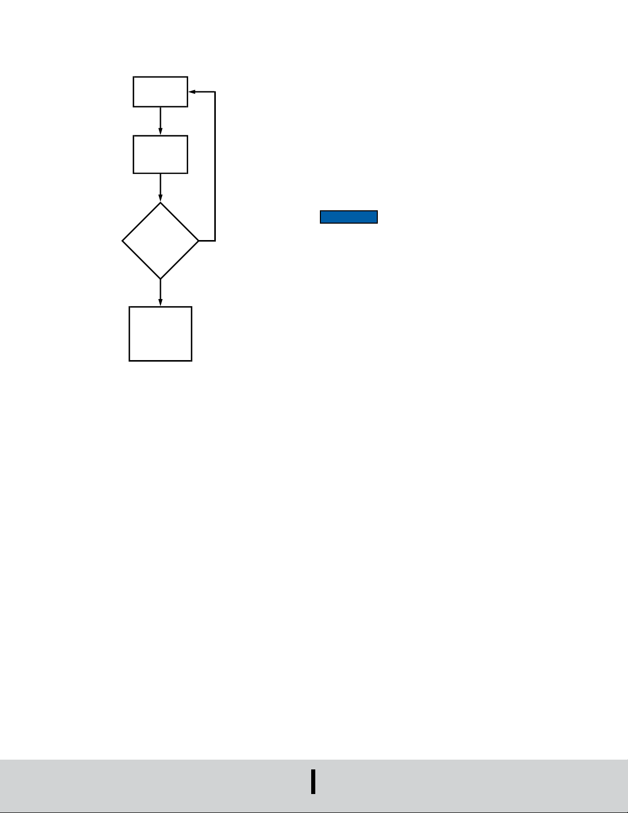
A.
STANDBY
DETECTION
B.
RELAY ON
DELAY
C. 1-MINUTE
WAITING NO
D.
RELAY OFF
DELAY
(RELAY OUTPUT)
DIRECTION
Figure 5