manuals.online logo
Brands
  1. Home
  2. •
  3. Brands
  4. •
  5. Dwyer Instruments
  6. •
  7. Accessories
  8. •
  9. Dwyer Instruments EFS2 Series User manual

Dwyer Instruments EFS2 Series User manual

317
Flow Transmitters, Electromagnetic,
Fixed Insertion
FLOW
DWYER INSTRUMENTS, INC. | www.dwyer-inst.com
INSERTION ELECTROMAGNETIC FLOW SENSOR
No Moving Parts,Durable,Easy Installation & Maintenance,1 to 12˝ Pipe (25 to 305 mm)
The SERIES EFS2 Insertion Electromagnetic Flow Transmitters is an economical,
xed insertion owmeter designed for use with the Series EFF ttings and tees to t
in pipe sizes ranging from 1 to 12˝ (2.5 to 30.5 cm) pipes. This series provides a pulse
rate output of the ow.
FEATURES/BENEFITS
• Long life cycle and less frequent maintenance with no moving parts to wear or break
and electrodes that discourage fouling
• Unaffected by change in temperature, density, viscosity or concentration
• Pulse output for use with a variety of displays and controllers for remote reading
• Easy meter mount display and transmitter accessories for local indication and analog
4 to 20 mA output
APPLICATIONS
• Contaminated liquid ow monitoring
• Flow of conductive liquids
• Water & wastewater treatment
• Industrial systems
• Irrigation applications
• Telemetry applications
4-15/16 [125.30]
4
[101.42]
3/32˝ THICK
GASKET
2-3/4
[69.90]
ELECTRODES
O-RING
Ø1-37/64
[40.13]
SENSOR BODY
[STAINLESS STEEL, BRASS OR PVC]
3-9/32
[83.45]
SPECIFICATIONS
Service: Compatible clean or dirty non-coating, conductive liquids.
Range: 0.28 to 20 ft/s (0.08 to 6.09 m/s).
Wetted Materials: Sensor: 316 SS, brass or PVC; Electrodes: Hastelloy®, metal;
Electrode Cap: PVDF; O-ring: EPDM (uoroelastomer optional).
Accuracy: ±1% FS.
Temperature Limits: Process: Brass/SS: 32 to 200°F (0 to 93°C); PVC: 32 to
130°F (0 to 55°C); Ambient: 0 to 160°F (-17 to 72°C).
Pressure Limits: Brass/SS: 200 psi (13.8 bar); PVC: 150 psi (10 bar).
Process Connection: See page reference u below.
Output: Current sinking, square wave pulse, opto-isolated, 550 Hz @ 20 ft/s.
Power Requirements: 12 to 25 VDC @ 250 mA; (12 to 25 VDC @ 40 mA (max.
250 mA) - LOP option).
Electrical Connection: Terminal block.
Conductivity: 20 microSiemens/cm.
Enclosure Material: Housing: Die-cast powder-coated aluminum.
Enclosure Rating: NEMA 4X (IP66).
Weight: 3 lb (1361 g).
ACCESSORIES
Series Description
BATv
RTI2w
PWD
Blind analog transmitter; converts pulse output to 4 to 20 mA
analog output; unit is loop powered, ts on the enclosure of the
meter, and is eld spannable.
Rate total indicator; converts pulse output to 4 to 20 mA analog
output with local ow rate and totalization display; unit is loop
powered, can t on the enclosure of the meter, and provides a
high/low ow alarm.
Pulse divider, for use with pacing electronic metering pumps;
unit divides the input frequency to any number from 1 to 9999
with the use of rotary switches to suit a number of metering
pump inputs. (See website)
Hastelloy® is a registered trademark of Hanes International
uProcess Connection: See page 318 (Series EFF)
vSee page 326 (Series BAT)
wSee page 326 (Series RTI)
SERIES EFS2
®
V
I
D
E
O
O
N
L
I
N
E
USA: California Proposition 65
WARNING: Cancer and Reproductive Harm - www.P65Warnings.ca.gov
MODEL CHART
Example EFS2 -1P -RFO EFS2-1P-RFO
Series EFS2 Insertion electromagnetic ow sensor
Size/
Material
1P
1B
1S
2P
2B
2S
3P
3B
3S
1 to 3˝ pipe, PVC
1 to 3˝ pipe, brass
1 to 3˝ pipe, 316 SS
4 to 10˝ pipe, PVC
4 to 10˝ pipe, brass
4 to 10˝ pipe, 316 SS
12˝ pipe, PVC
12˝ pipe, brass
12˝ pipe, 316 SS
Options BAT
RFO
IMM
FOR
LOP
Blind analog transmitter
Reverse ow output
Immersible (urethane potted electrical connection)
Fluoroelastomer O-ring
Low power (12 to 25 VDC @ 40 mA) (max 250 mA)
Note: Need to purchase with Series EFF tting for proper installation.
MODEL CHART
Stocked
Model Description Pipe Size Material
EFS2-1P
EFS2-1B
EFS2-1S
EFS2-2B
EFS2-3B
Insertion electromagnetic ow sensor
1 to 3˝
1 to 3˝
1 to 3˝
4 to 10˝
12˝
PVC
Brass
SS
Brass
Brass
Series EFS2
ELECTROMAGNETIC FLOW SENSOR
INSTRUCTIONS
F-EFS2
SPECIFICATIONS*
GENERAL INFORMATION
TABLE OF CONTENTS
General Information
 .......................................................................................................................................Page 1
Installation

............................................................................................................................................Page 2
 .........................................................................................................................
Page 3
.................................................................................................................................Page 4
Electrical Connections

.........................................................................................................Page 5
Connections Diagrams
Page 6

Page 7
Operation & Maintenance

 ...............................................................Page 8
Caution & Troubleshooting
......................................................................................................................Page 9
Page 1
TABLES AND DIAGRAMS
Features.................................................................................................................................................................Page 1
 ........................................................................................................................................................Page 1
................................................................................................................Page 2
 .........................................................................................................................
Page 3
.................................................................................................................................Page 4
...............................................................................................................................................Page 5
Page 6

 .................................................................................Page 7
 .............................................................................................Page 8
.....................................................................................................................................................Page 9

            
        
         


  
          
       
        

        

        

        

     



          

       






FEATURES

























Pipe Size
Materials Mechanical
Electrodes
Housing
Electrode Cap
O-Ring
Power Full Power
Low Power
Flow Rate
Temperature Ambient Temp
Fluid Temp : Brass/SS
Fluid Temp: PVC
Pressure Brass/SS
PVC
Minimum Conductivity
Calibration Accuracy
Output
Empty Pipe Detection
*Specications subject to change
Hastelloy® is a registered trademark of Haynes International, Inc.
Fitting Installation.



    



   

 




        








Chemical Injection or Fertigation.



         






INSTALLATION
Caution:     
       
   


INSTALLATION
STRAIGHT PIPE RECOMMENDATIONS
(X = pipe diameter)
Page 2
5X
DISTORTED FLOWS
Distorted
Flow Prole
Faster Flow
Causes Meter
To Read High
10X
Page 3
5X
10X
5X10X
5X
20X
5X
20X
30X
50X
Reduced Pipe
Two Elbows In Plane
Two Elbows, Out Of Plane
Expanded Pipe
Swirling Flow
Propeller Meter
Partially Open
Buttery Valve
Spiral Flow


POSITIONING THE METER
BEST POSITIONS
Caution:





Meter Installation.







Caution: 

     


EFS2
EFS2
EFS2
EFS2
EFS2
EFS2
Metallic Pipe
Earth
Ground
Grounding Clamp
INSTALLATION
Page 4 Page 5
ELECTRICAL CONNECTIONS
GROUNDING DIAGRAM
General Electrical Guidelines:
 

 

 

 

    






Power:

Forward Flow Output:     



Note:
Reverse Flow Output:  


Note:
PLACE FERRITE BEAD HERE
FULL PIPE RECOMMENDATIONS
Possible Problem:

Better Installation:

Possible Problem:

Better Installation:

Possible Problem:

Better Installation:

Housing
Screw
Grounding Guidelines:
   


For Metallic Pipe:



For Non-Metallic Pipe:






 
 
 
 
 
 
 
 
 
CONNECTIONS DIAGRAMS
Page 6
CONNECTIONS DIAGRAMS
COUNTER OR PLC
SERIES BAT 4 to 20 mA OUTPUT








EFS2 SERIES
BAT
SERIES EFS2






+
–





RTI DISPLAY AND PROPORTIONAL FEED






EFS2 SERIES
SERIES EFS2
4 to 20 mA Device























RTI DISPLAY AND 4 to 20 mA OUTPUT SERIES RTI
SERIES RTI
*

*


*

*

COUNTER OR PLC
DIGITAL INPUT






SERIES EFS2
DUAL SERIES RTI DISPLAYS
(Example of Bidirectional Connection)




*





SERIES RTI
SERIES RTI







Page 7
*
*

Page 8
OPERATION & MAINTENANCE
Zero Adjustment.        






full pipe with no ow



Minimum Flow.



Presence of Flow Indication.     




Filtering.




Calibration (“K-factor”).



tee tting

Find Your K-Factor Here
Page 9
Zero
Adjust
Pins
Electrode Coating.




         

saddle or weldolet
tting
3” 4” 6” 8” 10” 12”
KFACTORS SADDLES & WELDOLETS
Status
LED
PVC/Steel
Sch. 40
PVC/Steel
Sch. 80
Stainless
Steel (10S)
Stainless
Steel (40S)
Copper Tubing
(Type L)
Copper Tubing
(Type K)
Brass Pipe
Duct. Iron
(Class 52)
70.397
78.748
62.385
70.397
76.371
78.371
70.672
57.376
40.985
45.360
36.626
40.985
43.552
44.638
41.517
37.320
18.130
20.084
16.510
18.130
19.513
20.223
17.778
16.915
6.674
7.322
6.173
6.674
7.230
7.500
6.674
6.197
10.497
11.495
9.642
10.497
11.201
11.622
10.445
9.503
NOTE:

4.709
5.184
4.373
4.661
5.016
5.239
4.661
4.325
1” 1-1/2” 2” 3” 4” 6” 8” 10” 12”
• Min         
@ 0.28 ft/sec
• Max         
@ 20 ft/sec
FLOW RATE (GPM)
Nominal
Pipe Size
Reverse Output Option
Problem Probable Cause Try...






































CAUTION & TROUBLESHOOTING
TROUBLESHOOTING
Caution:





PL-OM-65200386-090412
9/04/12
Dwyer Instruments, Inc. • 102 Indiana Highway 212 • Michigan City, IN 46360 • USA
(P) 219.879.8868 • (F) 219.872.9057 • 1.800.872.9141 • www.dwyer-inst.com
WARRANTY/RETURN








This manual suits for next models

6

Other Dwyer Instruments Accessories manuals

Dwyer Instruments WTP-W series Installation and operating instructions

Dwyer Instruments

Dwyer Instruments WTP-W series Installation and operating instructions

Dwyer Instruments MFS Series User manual

Dwyer Instruments

Dwyer Instruments MFS Series User manual

Dwyer Instruments OSC-200 User manual

Dwyer Instruments

Dwyer Instruments OSC-200 User manual

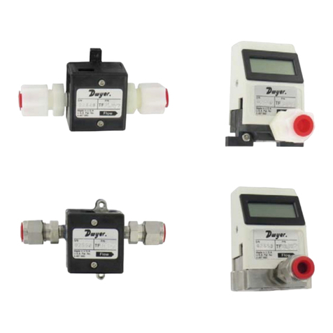
Dwyer Instruments TFP-LI Technical Document

Dwyer Instruments

Dwyer Instruments TFP-LI Technical Document

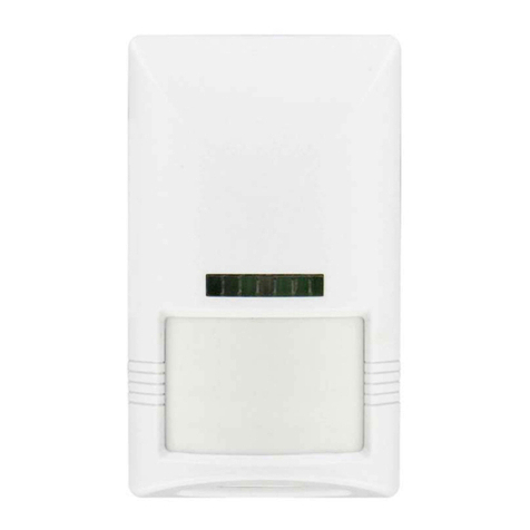
Dwyer Instruments OSW-100 User manual

Dwyer Instruments

Dwyer Instruments OSW-100 User manual

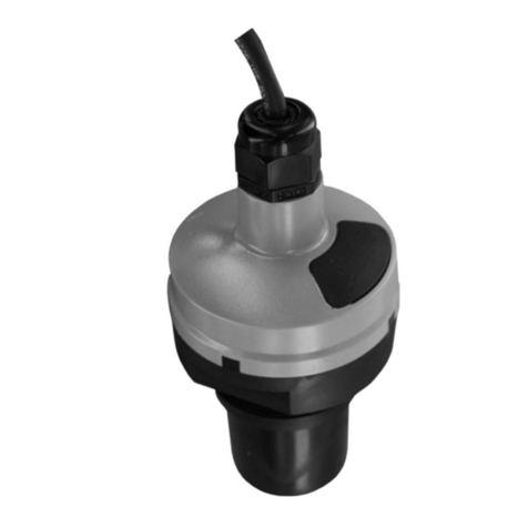
Dwyer Instruments ULS Series User manual

Dwyer Instruments

Dwyer Instruments ULS Series User manual

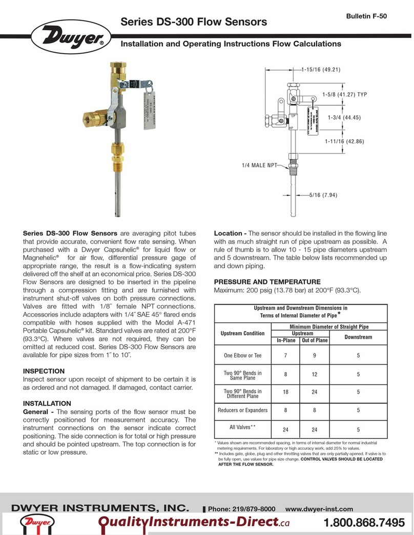
Dwyer Instruments DS-300 Series User manual

Dwyer Instruments

Dwyer Instruments DS-300 Series User manual

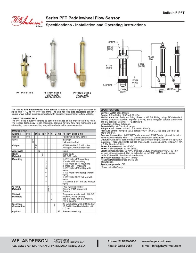
Dwyer Instruments W.E. ANDERSON PFT Series Installation and operating instructions

Dwyer Instruments

Dwyer Instruments W.E. ANDERSON PFT Series Installation and operating instructions

Popular Accessories manuals by other brands

Intermec Oracle-Ready CK31 instructions

Intermec

Intermec Oracle-Ready CK31 instructions

PCB Piezotronics M102B18 Installation and operating manual

PCB Piezotronics

PCB Piezotronics M102B18 Installation and operating manual

Waterpik WP-320 Series quick start guide

Waterpik

Waterpik WP-320 Series quick start guide

Sterilize+ UV-C SANITIZING TOWER manual

Sterilize+

Sterilize+ UV-C SANITIZING TOWER manual

ipf electronic PT65 Series manual

ipf electronic

ipf electronic PT65 Series manual

Explore Scientific RGT1001 instruction manual

Explore Scientific

Explore Scientific RGT1001 instruction manual

Crivit 322171 1901 Instructions for use

Crivit

Crivit 322171 1901 Instructions for use

EVERSPRING TSM04 user manual

EVERSPRING

EVERSPRING TSM04 user manual

Champion SKYBIRD Owner's/operator's manual

Champion

Champion SKYBIRD Owner's/operator's manual

Yamaha FC7 owner's manual

Yamaha

Yamaha FC7 owner's manual

Everlast 4812 owner's manual

Everlast

Everlast 4812 owner's manual

Fiamma F65eagle Series Installation and usage instructions

Fiamma

Fiamma F65eagle Series Installation and usage instructions

cosihome EB-D3 instruction manual

cosihome

cosihome EB-D3 instruction manual

Electro-Harmonix 22500 quick start guide

Electro-Harmonix

Electro-Harmonix 22500 quick start guide

Toshiba TCB-SIR41UM-E Operation manual

Toshiba

Toshiba TCB-SIR41UM-E Operation manual

Met One Instruments 020C Operation manual

Met One Instruments

Met One Instruments 020C Operation manual

EVAPCO ATC-E Operation and maintenance instruction manual

EVAPCO

EVAPCO ATC-E Operation and maintenance instruction manual

Scosche X3 manual

Scosche

Scosche X3 manual

manuals.online logo
manuals.online logoBrands
  • About & Mission
  • Contact us
  • Privacy Policy
  • Terms and Conditions

Copyright 2025 Manuals.Online. All Rights Reserved.