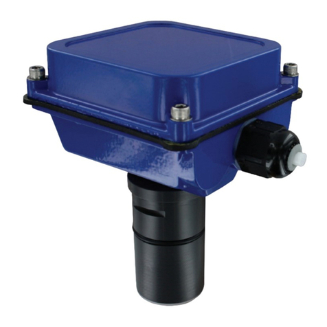
Dwyer Instruments ULS Series User manual

L‐ULS
RevAMN8905701of30
SeriesULS
SmallTankUltrasonicTransmitter,SwitchandController
SeriesULSS,ULSM,ULSLManual

2of30MN890570RevA
INTRODUCTION/TABLEOFCONTENTSStepOne
SeriesULSisaninnovativelevelsensorfamilythatreplacesfloat,conductanceandpressuresensorsthatfail
duetocontactwithdirty,stickingandscalingmediainsmall(<4’/1.25m)tomedium(<18’/5.5m)talltanks.
Appliedinskid,machine,toolandprocessapplications,thegeneralpurposesensorsareavailablewithsingle
andmulti‐functioncapabilitiesincludingmeasurement,switchingandcontrol.
Features
SimpleconfigurationwithULSX‐CALsoftware,nomoretargetcalibration
AdjustableLoopFail‐Safe
EasytoreversemAoutput
Increasedoutputfiltering
TableofContents
Specifications:.........................................................................................................................................................3
Dimensions: .........................................................................................................................................................4
SafetyPrecautions:................................................................................................................................................5
Components:.........................................................................................................................................................6
GettingStarted:......................................................................................................................................................7
USBFobInterface:.....................................................................................................................................7
ULSX‐CAL: .........................................................................................................................................................8
Configuration:............................................................................................................................................9
TankLevels&RelayValues:.....................................................................................................................16
WritetoUnit&WiringDiagram:.............................................................................................................17
Wiring: .......................................................................................................................................................18
WireConnections:....................................................................................................................................18
SwitchInductiveLoads:............................................................................................................................19
Installation:.......................................................................................................................................................20
MountingGuide:......................................................................................................................................20
FittingSelection:......................................................................................................................................21
TankAdapter:...............................................................................................................................21
Riser:............................................................................................................................................21
Flange:..........................................................................................................................................22
SideMountFitting:......................................................................................................................22
StandPipe:...................................................................................................................................23
AdvancedFeature:...............................................................................................................................................24
Appendix:.......................................................................................................................................................26
UpdatingULSX‐CALSoftware:..................................................................................................................26
UpdatingTransmitterFirmware:.............................................................................................................27
Troubleshooting:..................................................................................................................................................28
FactoryDefaults:......................................................................................................................................28
SolutionTable:.........................................................................................................................................29
Maintenance&Repair:........................................................................................................................................30
Rev5MN8905703of30
SPECIFICATIONS StepTwo
Range:ULSS:49.2”(1.25m)
ULSM:9.8’(3.0m)
ULSL:18.0’(5.5m)
Accuracy:ULSS:0.125”(3mm)
ULSM:+/‐0.2%ofrange
ULSL:+/‐0.2%ofrange
Resolution:ULSS:0.019”(0.5mm)
ULSM:0.039”(1mm)
ULSL:0.079”(2mm)
Deadband:ULSS:2”(5cm)
ULSM:4”(10cm)
ULSL:8”(20cm)
Beamwidth:ULSS:2”(5cm)dia.
ULSM:2”(5cm)dia.
ULSL:3”(7.6cm)
Configuration:ULSX‐CAL®PC
WindowsUSB2.0
Memory:Non‐volatile
Supplyvoltage:12‐28VDC
Consumption:0.5W
Loopresistance:400Ohmsmax
Signaloutput:4‐20mA,two‐wire
Signalinvert:4‐20mAor20‐4mA
Signalfail‐safe:4mA,20mA,21mA,22mAor
holdlast
Contacttype:(4) SPSTrelays
Contactrating:60VA,1Amaximum
Contactfail‐
safe:
Powerloss:Holdlast,
Poweron:Open,closeorholdlast
Hysteresis:Selectable
Processtemp.:F:20°to140°
C:‐7°to60°
Temp.comp.:Automatic
Ambienttemp.:F:‐31°to140°
C:‐35°to60°
Pressure:MWP=30PSI
Enclosurerating:Type6Pencapsulated,corrosion
resistance&submersible(IP68)
Encl.material:Polycarbonate
Strainrelief
material:
Santoprene
Trans.material:PVDF
Cablejacket
material:
Polyurethane
Cabletype:9‐conductor,shielded
Cablelength:48”(1.2m)
Processmount:ULSS:1”NPT(1”G)
ULSM:1”NPT(1”G)
ULSL:2”NPT(2”G)
Mountgasket: FKM
Classification: Generalpurpose
Compliance:CE,RoHS

4of30MN890570RevA
DIMENSIONS StepThree
SeriesULSLSeriesULSM
SeriesULSS

Rev5MN8905705of30
SAFETYPRECAUTIONSStepFour
AboutthisManual:PLEASEREADTHEENTIREQUICKSTARTPRIORTOINSTALLINGORUSINGTHIS
PRODUCT.ThismanualincludesinformationontheSeriesULSUltrasonicLevelSwitch,controllerand
transmitterfromDwyerInstruments,Inc.Pleaserefertothepartnumberlocatedontheswitchlabeltoverify
theexactmodelconfiguration,whichyouhavepurchased.
User’sResponsibilityforSafety:DwyerInstruments,Incmanufacturesabroadrangeoflevelsensing
technologies.Whileeachofthesesensorsisdesignedtooperateinawidevarietyofapplications,itistheuser’s
responsibilitytoselectasensormodelthatisappropriatefortheapplication,installitproperly,performtestsof
theinstalledsystem,andmaintainallcomponents.Thefailuretodosocouldresultinpropertydamageor
seriousinjury.
ProperInstallationandHandling:Onlyprofessionalstaffshouldinstalland/orrepairthisproduct.Install
thetransmitterwiththeincludedFKMgasketandneverovertightenthetransmitterwithinthefitting.Always
checkforleakspriortosystemstart‐up.
WiringandElectrical:Asupplyvoltageof12to28VDCisusedtopowertheSeriesULS.Electricalwiringofthe
transmittershouldbeperformedinaccordancewithallapplicablenational,state,andlocalcodes.Note:Series
ULSuseslatchingrelays.Whenpowerisremovedtothesensor,therelayswillremainintheirlaststate.Ex:Ifthe
relayisenergized,whenpowerisremoved,therelaywillremaininanenergizedstate.
MaterialCompatibility:TheenclosureismadeofPolycarbonate(PC).Thetransducerismadeof
PolyvinylideneFluoride(PVDF).Makesurethatthemodel,whichyouhaveselected,ischemicallycompatible
withtheapplicationmedia.
Enclosure:Whilethetransmitterhousingisliquid‐resistanttheSeriesULSisnotdesignedtobe
operationalwhenimmersed.Itshouldbemountedinsuchawaythattheenclosureandtransducerdonot
comeintocontactwiththeapplicationmediaundernormaloperationalconditions.
Safety
Installationshouldbedonebyproperlytrainedstaff
Supplyvoltageshouldneverexceedamaximumof28VDC
Makesurethesensorischemicallycompatiblewithyourapplication
Designafail‐safesystemthataccommodatesthepossibilityofsensorand/orpowerfailure
Thissensorshouldnotbeusedinclassifiedhazardousenvironments
MakeaFail‐SafeSystem:Designafail‐safesystemthataccommodatesthepossibilityoftransmitter
and/orpowerfailure.DwyerInstruments,Increcommendstheuseofredundantbackupsystemsandalarms
inadditiontotheprimarysystem.
Flammable,ExplosiveorHazardousApplications:SeriesULSshouldnotbeusedwithinclassified
hazardousenvironments.
Warning:AlwaysusetheFKMgasketwheninstallingtheSeriesULS,andmakesurethatallelectrical
wiringoftheswitchisinaccordancewithapplicablecodes.

6of30MN890570RevA
COMPONENTSStepFive
SeriesULSisofferedindifferentmodels.Dependingonthemodelpurchased,youmayormaynothavebeen
shippedallthecomponentsshownbelow.Youdohowever,needaSeriesULS,USBFobandFKMgasketto
configure,installandoperateSeriesULS.
FKMGasket
oULS‐ACC‐SGK–usedwithULSSseries
oULS‐ACC‐MGK–usedwithULSMseries
oULS‐ACC‐LGK–usedwithULSLseries
USBFob
oPart#ULS‐ACC‐USB
QuickStartGuide
*Outputs
1. 4‐20mA,looppoweredoutput
2. 4SPST60VArelays
P/NMax.RangeDeadBandThreadFob*Outputs
ULSS‐10 4.1’(1.25m)2”(5cm)1”NPT NoFob1,2
ULSS‐11 4.1’(1.25m)2”(5cm)1”NPT FobIncluded1,2
ULSS‐20 4.1’(1.25m)2”(5cm)1”GNoFob1,2
ULSS‐21 4.1’(1.25m)2”(5cm)1”GFobIncluded1,2
ULSM‐10 9.8’(3.0m)4”(10cm)1”NPT NoFob 1,2
ULSM‐11 9.8’(3.0m)4”(10cm)1”NPT FobIncluded1,2
ULSM‐20 9.8’(3.0m)4”(10cm)1”GNoFob 1,2
ULSM‐21 9.8’(3.0m)4”(10cm)1”GFobIncluded1,2
ULSL‐10 18.0’(5.5m)8”(20cm)2”NPT NoFob 1,2
ULSL‐1118.0’(5.5m)8”(20cm)2”NPT FobIncluded1,2
ULSL‐20 18.0’(5.5m)8”(20cm)2”GNoFob 1,2
ULSL‐21 18.0’(5.5m)8”(20cm)2”GFobIncluded1,2

Rev5MN8905707of30
GETTINGSTARTEDStepSix
SeriesULSisconfiguredthroughULSX‐CAL,aPCsoftwareprogram.ULSX‐CALisafreedownloadfromDwyer
Instrument,Inc’swebsite.YoumustdownloadandinstallULSX‐CALpriortopluggingintheUSBFob.Please
gotohttp://www.Dwyer‐Inst.com/software,clickonULSX‐CAL.Pleaseobservethefollowingrequirements
fortheULSX‐CALsoftware:
ULSX‐CALSystemRequirements
Windows(R)2000,Windows(R)XP,Windows
Vista(R),Windows(R)7
32or64‐bitoperatingsystem
1USB2.0port
10mBharddrivespace
256mBRAM
Internetconnection
USBFobInterface:TheSeriesULScommunicateswithULSX‐CALthroughaUSBinterface(p/n:ULS‐ACC‐USB)
calledaFob.BeforepluggingyourFobintoyourcomputer’sUSBport,besurethatyouhaveinstalledULSX‐
CALonyourcomputer.
Connectthered,green,whiteandblackwiresfromSeriesULSintothecorrectterminalsontheFob.Tighten
thescrewsontheterminalsandplugyourFobintotheUSBportofyourcomputer.
Wiringidenticalforallseries–UseonlytheRed,Black,GreenandWhitewires.
ThemaximumcabledistancebetweenthecomputerandSeriesULSis15’(4.6m).Thisonlyapplieswhen
configuringtheSeriesULS.
OnceSeriesULSisconfiguredandpriortoinstallation,isolatethewhiteandgreenwiresfromactivepower
topreventashortoftheconfigurationcircuit.
WhenusingtheFob,donotaddVDCpower.TheFob,whenconnectedtothecomputer,willprovidethe
requiredpowertotheSeriesULS.
Windows(R)isaregisteredtrademarkofMicrosoftCorporation
WindowsVista(R)isaregisteredtrademarkofMicrosoftCorporation

8of30MN890570RevA
ULSX‐CALStepSeven
WithSeriesULSconnectedtoyourcomputer,opentheULSX‐CALsoftwarebyclickingontheULSX‐CALicon.
Followsteps1‐3toconfigurethetransmitter.Click“Help”inthelowerrighthandcornerandopenthehelp
menuofULSX‐CALforadditionalinstructionsonULSX‐CAL.IfyouneedadditionalassistanceusingULSX‐CAL,
pleasecontactaDwyerInstruments,IncApplicationsEngineerat(800)872‐9141.
AboveScreenCaptureisfortheSeriesULSS.

Rev5MN8905709of30
ULSX‐CALCONFIGURATIONStepSeven
ThissectionofULSX‐CALiswhereyouselecttheapplication’sconfigurationsettings.Startfromthetopand
worktothebottom,choosingtheselectionsthatareapplicabletoyourconfiguration.“NotApplicable”will
automaticallyshowwhenaselectiondoesn’tapplytoyourconfigurationsettings,andyoumaymoveon.All
configurationsettingsmustbeselectedorhave“NotApplicable”beforeyoucancontinuetothenextstep.
Note:PressingtheClearScreenbuttonwillresettheconfigurationtableandallowaccesstoallofthefeatures.
NumberofPumps:Thisfeatureallowsyoutoselectthenumberof
pumpsorvalvesusedwithSeriesULS.Thisisthesettingthatactivates
thecontrolcapabilitiesofuptotworelays.Controlrelaysareoften
referredtoaslatchingrelays.
oSwitch/AlarmsOnly–Therelayswillbestandardsinglepoint
relays(Highand/orLowalarms).Relaysarenon‐latching.
o1‐ Pump/Valve–Onerelaywillbeconfiguredasacontrolor
latchingrelay(relaywillhaveastartlevelandaseparatestop
level).Usethissettingtocontrolonepumporvalvefor
automaticfillingoremptyingofatank.
o2‐Pumps/Valves–Tworelaysareconfiguredascontrolor
latchingrelays.Eachrelaywillhaveauniquestartlevelanda
commonstoplevel.Usethissettingtocontroltwopumpsor
valvesforautomaticfillingoremptyingofatank.
o4‐20mATransmitterOnly–Thissettingwilldisengageallofthe
relays.Usethisfunctionifyouarenotusinganyrelaysand
usingonlythe4‐20mAcurrentoutput.
Note:Rightclickonanymenuthatyoumayhavequestionsontoopenthehelpmenu.
Note:Toreset,presstheClearScreenbutton.

10of30MN890570RevA
ULSX‐CALCONFIGURATION(continued)StepSeven
Pump/ValveAction:Thisfeatureallowsyoutoselectifthepumpsor
valveswillbeusedtoautomaticallyfilloremptythetank.For2‐
Pump/Valvemode,bothdevicesmustbethesame(automaticfillor
empty).Youcannotsetonerelayforfillandtheotherforempty.
oEmptiesTank–Willsetrelay(s)toautomaticallyemptyatank.
StartlevelwillbeabovetheStoplevelforeachrelay.
oFillsTank–Willsetrelay(s)toautomaticallyfillatank.Start
levelwillbebelowtheStoplevelforeachrelay.
oNotApplicable–Appearswhenthisfunctionisnotavailable
(suchaswhenSwitch/AlarmsOnlyor4‐20mATransmitters
Onlyareselected).
EmptiesTankFillsTank
(AutoEmpty)(AutoFill)
Note:Rightclickonanymenuthatyoumayhavequestionsontoopenthehelpmenu.
Note:Toreset,presstheClearScreenbutton.

Rev5MN89057011of30
ULSX‐CALCONFIGURATION(continued)StepSeven
Pump/ValveMode:Thisfeatureallowsyoutoselectthemodefora
controlorlatchingrelay.Pump/Valvemodeisnotactivefor
Switch/AlarmsOnlyor4‐20mATransmitterOnly.
oSimplex–Allowsfortherelaytobeusedasanautomaticfillor
empty.Thisisthedefaultandonlyconfigurationwhen1‐
Pump/Valveisselected.
oSimplexusedtoEmptyTank(example)
oLead/Lag–Allowsforthetworelaystohaveuniquestartlevels
andacommonstoplevel.Thefirstrelaywillbeidentifiedas
theleadrelayandthesecondrelayasthelag.Eachtimethe
leadlevelisreached,thefirstrelaywillalwaysstart.Thelag
relaywillonlystartwhenthelaglevelisreached.Allrelayswill
stopatthecommonofflevel.
oLead/LagusedtoEmptyTank(example)
oDuplex‐Allowsforthetworelaystohavetwodifferentstart
levels,acommonstoplevelandwillalternatetherelayswhen
thefirststartlevelisreached.Thetworelayswillalternate
eachtimetheleadlevelisreachedandtheremainingrelaywill
startwhenthelaglevelisreached.Allrelayswillstopatthe
commonofflevel.
oDuplexusedtoEmptyTank(example)
oNotApplicable–Appearswhenthisfunctionisnotavailable
(suchaswhenSwitch/AlarmsOnlyor4‐20mATransmitters
Onlyareselected).
Note:Rightclickonanymenuthatyoumayhavequestionsontoopenthehelpmenu.
Note:Toreset,presstheClearScreenbutton.

12of30MN890570RevA
ULSX‐CALCONFIGURATION(continued)StepSeven
RelayFail‐Safe:Thisfeatureallowsyoutoselectthefail‐safestatefor
therelays.Whenthesensorregainssignal,theoutputcurrentwill
revertbacktothecurrentlevelcondition.
oRelaysOff‐ TherelayswillreverttotheOFFstate.Appears
whenSwitch/AlarmsOnlyisselected.
oRelaysOn‐TherelayswillreverttotheONstate.
AppearswhenSwitch/AlarmsOnlyisselected.
oHoldState‐Therelay(s)willremaininthesamestateasthe
lastechodetected.Whenthesensorregainssignal,therelays
willreverttothelevelwhenthesignalwasregain.
oPump/ValvesOff‐ TherelayswillreverttotheOFFstate.
Appearswhen1‐Pump/Valveor2‐Pumps/Valvesareselected.
oPump/ValvesOn‐ TherelayswillreverttotheONstate.
Appearswhen1‐Pump/Valveor2‐Pumps/Valvesareselected.
oNotApplicable–Appearswhenthisfunctionisnotavailable
(suchaswhenTransmittersOnlyareselected).
Note:Rightclickonanymenuthatyoumayhavequestionsontoopenthehelpmenu.
Note:Toreset,presstheClearScreenbutton.

Rev5MN89057013of30
ULSX‐CALCONFIGURATION(continued)StepSeven
Switch/AlarmConfiguration:Thisfeatureallowsyoutoselect the
operationfortheswitches/alarms(usedasahighorlowalarm).This
settingadjuststhenumberofavailablerelaysbasedupontheprevious
settings.
oNoAlarm–Turnsoffalloftheremainingrelays.
oHighAlarmOptions–Setfrom1to4HighAlarms(1‐High,2‐
High,3‐High,4‐High).
oLowAlarmOptions–Setfrom1to4LowAlarms(1‐Low,2‐
Low,3‐Low,4‐Low).
oCombinationAlarms–SetacombinationofHighandLow
Alarms(1‐Low1‐High,1‐Low2‐High,2‐Low1‐High,2‐Low2‐
High,1‐Low3‐High,3‐Low1‐High).
oNotApplicable–Appearswhenthisfunctionisnotavailable
(suchaswhenTransmittersOnlyisselected).
HighAlarmOptionsLowAlarmsOptionsCombinationAlarms
(4High)(4Low)(2Highand2Low)
Note:Rightclickonanymenuthatyoumayhavequestionsontoopenthehelpmenu.
Note:Toreset,presstheClearScreenbutton.

14of30MN890570RevA
ULSX‐CALCONFIGURATION(continued)StepSeven
SwitchHysteresis/Deadband:Thisfeatureallowsyoutoselecta
hysteresisordeadbandfortheremaininghighand/orlowalarms.
oOptionsforHysteresis/Deadband–NoHysteresis,¼”,½”,1”,
2”,½cm,1cm,2cm,5cmorNotApplicable.
oHighAlarms–Relayactivatesabovesetpoint.Relaywill
deactivatewhenlevelgoesbelowthesetpointplusthevalueof
thehysteresis.
oLowAlarms–Relayactivatesbelowsetpoint.Relaywill
deactivatewhenlevelgoesabovethesetpointplusthevalueof
thehysteresis.
HighAlarmw/HysteresisLowAlarmw/Hysteresis
Note:Rightclickonanymenuthatyoumayhavequestionsontoopenthehelpmenu.
Note:Toreset,presstheClearScreenbutton.

Rev5MN89057015of30
ULSX‐CALCONFIGURATION(continued)StepSeven
LoopFail‐Safe:Thisfeatureallowsyoutoselectthefail‐safecurrent
outputifthesensorfailstodetectareturnsignal.Whenthesensor
regainssignal,theoutputcurrentwillrevertbacktothecurrentlevel
condition.
oHoldLastValue‐Theoutputwillremaininthesamestateas
thelastechodetected.Example:Iftheoutputwas6.7mAjust
priortothelostsignal,thedevicewillcontinuetooutput6.7
mA.Sensorwillindicatethelevelwhensignalwasregain.
oEmpty‐ Theoutputwillreverttothecurrentvalueforan
emptycondition.When“4mAatBottom”isselected,the
sensorwilloutput4mAwhenafail‐safeconditionoccurs.If
“20mAatBottom”isselected,thesensorwilloutput20mA
whenafail‐safeconditionoccurs.
oFull‐ Theoutputwillreverttothecurrentvalueforafull
condition.When“4mAatBottom”isselected,thesensorwill
output20mAwhenafail‐safeconditionoccurs.If“20mAat
Bottom”isselected,thesensorwilloutput4mAwhenafail‐
safeconditionoccurs.
oOverfill(21mA)‐Theoutputcurrentwillgoto21mAwhenthe
returnsignalislost.
oOverfill(22mA)‐Theoutputcurrentwillgoto22mAwhenthe
returnsignalislost.
OutputatEmpty:Thisfeatureallowsyoutoselecttheorientationof
the4to20mAoutput(4to20mAor20to4mA).Choosewhich
outputsettingbestfitstheapplication.Typicalinstallationsareset
with4mAatBottom.Thiswillnotaffecttheperformanceofthe
sensorotherthantheoutputoftheSeriesULS.ULSX‐CAL’sfactory
defaultis4mAatbottomand20mAattop.Whenconnectingyour
sensortoadisplay,youmustaccountforyouroutputsettings.
o4mAatBottom‐Theoutputcurrentwillbe4mAwhenthe
sensormeasuresanemptytankand20mAwhenthesensor
measuresafulltank.
o20mAatBottom‐Theoutputcurrentwillbe20mAwhenthe
sensormeasuresanemptytankand4mAwhenthesensor
measuresafulltank.
Note:Rightclickonanymenuthatyoumayhavequestionsontoopenthehelpmenu.
Note:Toreset,presstheClearScreenbutton.

16of30MN890570RevA
ULSX‐CALTANKLEVELS/WRITETOUNITStepSeven
ULSX‐CAL‐TankLevels:ThissectionofULSX‐CALiswhereyouenterapplicationmeasurementvalues.This
appliestoallversionsoftheSeriesULS.YoumustentertheSensorHeightandFillHeightvalues.
FortheSeriesULSS,ULSMandULSL,theSensorHeightandFillHeightvaluesdeterminethe
operationalrangeforthe4‐20mAoutput.
SensorHeight: Distancefrom
thebottomofthetanktothe
bottomofthetransducer.
FillHeight:Distancefromthe
bottomofthetanktothe
maximumliquidheight.
ULSX‐CAL‐RelayValues:(SeriesULSS,ULSMandULSLonly):ThissectionofULSX‐CALiswhereyouenter
theoperationalvaluesforrelays.Youmustentervalueswithinallofthefieldsshown.Thevaluefieldsshown
arebasedupontheconfigurationoftheSeriesULS.Allvaluesmustbeintheunitsofoperationselected
aboveandarebaseduponunitsofliquid.AllrelayvaluesmustbegreaterthanLiquidEmpty(0)andlessthan
LiquidFull(FillHeight).
Example: Thissampleshows4
HighLevelAlarms.Asthe
levelincreasesfromthe
bottom–up,eachalarmwill
activateat4”increments.
Example:Thissampleshowsa
2‐PumpLead/Lagoperation
withaHighandLowalarm.
Thepumpswillautomatically
emptythetankandthe
alarmswillactivateifthelevel
getstoohighorlow.

Rev5MN89057017of30
ULSX‐CAL‐WRITETOUNITStepSeven
Afteryouhaveenteredconfigurationsandtank
values,click“WritetoUnit”andsendthe
configurationtoyourSeriesULS.NowuseULSX‐CAL’s
filemanagementfeaturestosaveyourconfiguration
byclicking“SaveConfigFile”andprintyourwiring
diagrambyclicking“WiringDiagram.”
WritetoUnit
Wiringdiagram
SaveConfigFile
WiringDiagram‐Sample
DiagramwillchangebasedupontheconfigurationoftheSeriesULS,
useULSX‐CALtoviewappropriatewiringdiagram.
WiringSeriesULS:OnceSeriesULShasbeeninstalled,followtheWiringDiagramprovidedbytheULSX‐CAL
software.Atypicalwiringdiagramisshownabove.DwyerInstruments,Increcommendsusingaqualified
licensedelectriciantowireSeriesULSandyourapplication’scomponents.
ConfigureyourSeriesULSwithULSX‐CALandusethewiringdiagrambuttontoviewtheappropriate
diagram.Eachconfigurationwillhaveitsownuniquediagram.Thediagramaboveisonlyasample
andshouldnotbeusedasawiringdiagram.
Alwaysusestepperrelaysbetweenthesensorandexternalloads.ForDCcircuitsuseacatchdiode
suchas1N4148,shownonthewiringdiagramshownaboveandsuppliedbyULSX‐CAL.
OnceSeriesULSisconfigured,isolatethewhiteandgreenwiresfromactivepowertopreventa
shortoftheconfigurationcircuit.

18of30MN890570RevA
WIRINGStepEight
WireConnections:
Red&Black:RedandBlackleadsareforconnectiontoa12‐28VDCpowersupplyortoa4‐20mAlooppower
source(SeriesULSS,ULSM&ULSLonly).Theredandblackwirescanbeextendedupto1,000feetusinga22
gaugeorlargerwire,howeverdonotextendthegreenandwhitewires.
White&Green:WhiteandGreenleadsarereservedforusewithULSX‐CALandshouldnotbeconnected
duringusageintheapplication.ThesewiresshouldnotbeconnectedtoULSX‐CALwhilepowerissupplied
fromanysourceotherthantheULS‐ACC‐USBFob.Themaximumcabledistancebetweenthecomputerand
SeriesULSis15’.
Neverallowthewhiteorgreenwirestotouchanypowersupply.
Blue,Orange,Yellow,Purple&Brown:Blue,Orange,Yellow&Purplewiresaretherelaycontacts(normally
open)fromeachoftherelaysrespectively.TheBrownwireisthecommonforalltherelays.Relayselectionis
determinedbytheconfigurationinULSX‐CAL.Note:SeriesULSuseslatchingrelays.Whenpowerisremovedto
thesensor,therelayswillremainintheirlaststate.Ex:Iftherelayisenergized,whenpowerisremoved,the
relaywillremaininanenergizedstate.
Generalnotesforelectricalconnections,usageandsafety:
Wherepersonalsafetyorsignificantpropertydamagecanoccurduetoaspill,theinstallationmust
havearedundantbackupsafetysysteminstalled.
Wiringshouldalwaysbecompletedbyalicensedelectrician.
Supplyvoltageshouldneverexceed28VDC.
Alwaysusestepperrelaysbetweenthesensorandexternalloads.ForDCcircuitsuseacatchdiode
suchas1N4148,shownonpreviouspage.
Protectthesensorfromexcessiveelectricalspikesbyisolatingthepower,wheneverpossible.
Thesensormaterialsmustbechemicallycompatiblewiththeliquidstobemeasured.
Designafail‐safesystemforpossiblesensorand/orpowerfailure.
NeverusethesensorinenvironmentsclassifiedasHazardous.

Rev5MN89057019of30
WIRINGStepEight
SwitchingInductiveLoads:Theuseofsuppressors(snubbers)isstronglyrecommendedwhenswitching
inductiveloadstopreventdisruptingthemicroprocessor’soperation.Thesuppressorsalsoprolongthelifeof
therelaycontacts.SuppressioncanbeobtainedwithacatchdiodeforDCcircuitsandaresistor‐capacitor(RC)
forACcircuits.
CatchDiode
Alwaysusestepperrelaysbetweenthesensorandexternalloads.
ForDCcircuitsuseacatchdiodesuchas1N4148,shownonleft.
RefertothefollowingcircuitsforRCnetworkassemblyandinstallation:
ChooseRandCasfollows:
R:0.5to1Ohmsforeachvoltacrossthecontacts
C:0.5to1μFforeachampthroughclosedcontacts
Notes:
1. Usecapacitorsratedfor250VAC.
2. RCnetworksmayaffectloadreleasetimeofsolenoidloads.Check
toconfirmproperoperation.
3. InstalltheRCnetworkatthemetersrelayscrewterminals.AnRC
networkmayalsobeinstalledacrosstheload.Experimentforbest
results.
VoltageOutput:SeriesULScanbeusedasa0to5or0to10VDCoutputdevice.Aresistorwillneedtobe
addedtothecircuittoenableavoltageoutput(refertothewiringdiagrambelow).
0‐5VDCoutput
oAdda250Ohmresistor
oActualoutputwillbe0.8to5VDC
0‐10VDCoutput
oAdda500Ohmresistor
oActualoutputwillbe2to10VDC
WhenusingULSX‐CAL,underNumberofPumps,select4‐20mATransmitterOnlytosimplifytheconfiguration
inULSX‐CAL.

20of30MN890570RevA
INSTALLATIONStepNine
TheSeriesULSshouldalwaysbemountedperpendiculartotheliquidsurfaceandinstalledusingtheprovided
FKMmountinggasket.Makesurethatthefittingandtransmitterthreadsarenotdamagedorworn.Always
hand‐tightenthetransmitterwithinthefitting.Performaninstalledleaktestundernormalprocessconditions
priortosystemstartup.Note:ThepreferredmountingfittingfortheSeriesULSS&ULSMistheULS‐ACC‐121
(2”threadx1”thread)reducerbushing.
MountingGuide
1. Donotmountatanangle
2. Liquidshouldneverenterthedeadband
3. SideWall:
a. Mountatleast2”fromthesidewall
b. ForSeriesULSL‐mountatleast3”fromthesidewall
4. Donotmountwhereobstacleswillintrudeonsensor’sbeamwidth
a. SeeSpecifications,StepTwo
5. Donotmountinavacuum
6. Avoidmountinginthecenterofadometoptank.
7. Inconebottomtank,positionthesensoroverthedeepestpartofthetank.
Donotinstallat
anglerelativetothe
liquid.
Donotinstallwithin
2”oftanksidewall.
(3”forSeriesULSL)
Donotinstallwith
objectsinthebeam.
Donotinstallin
applicationswith
vacuum.
Installationinexistingfittings:IftheexistingfittingislargerthanthethreadsoftheSeriesULS,selecta
reducerbushingsuchastheULS‐ACC‐121(2”threadx1”thread)orULS‐ACC‐131(3”threadx2”thread).
MetalTanks(SeriesULSS&ULSM):DwyerInstruments,Incultrasonictransmittershavebeenoptimizedfor
useinnon‐metallicfittings.
1. Forbestperformance,avoidtheuseofmetallicfittings.
a. Useaplastic2”x1”reducerbushing,suchastheULS‐ACC‐121oraplastic1”flange,suchasthe
ULS‐ACC‐312formetallictanks.
2. Whileinstallationsdirectlyintoa1”metalfittingarenotrecommended,acceptableresultsmaybe
obtainedifthe1”fittingisahalfcouplinginformandtheouterdiameterofthecouplingistightly
wrappedinvinyltapetodampenvibrations.
This manual suits for next models
15
Table of contents
Other Dwyer Instruments Accessories manuals

Dwyer Instruments
Dwyer Instruments OSW-100 User manual

Dwyer Instruments
Dwyer Instruments DS-300 Series User manual

Dwyer Instruments
Dwyer Instruments OSC-200 User manual

Dwyer Instruments
Dwyer Instruments MFS Series User manual

Dwyer Instruments
Dwyer Instruments EFS2 Series User manual

Dwyer Instruments
Dwyer Instruments TFP-LI Technical Document

Dwyer Instruments
Dwyer Instruments W.E. ANDERSON PFT Series Installation and operating instructions

Dwyer Instruments
Dwyer Instruments WTP-W series Installation and operating instructions