DX Engineering DXE-RBS-1P User manual

Reversible Beverage System
DXE-RBS-1P
DXE-RBS-1P-INS Rev 2
© DX Engineering 2009
P.O. Box 1491 · Akron, OH 44309-1491
Phone: (800) 777-0703 · Tech Support and International: (330) 572-3200

- 2 -
Table of Contents
Introduction 3
Features 3
Specifications 3
Typical Reverse Beverage System Layout - Figure 1 4
Additional Parts Required 5
Hardware 5
Ground Rods 5
Feedline 5
Antenna Wire 6
Power Supply 6
Installation 6
Site Selection 6
Proximity to Transmitting Antennas 7
Lightning Protection 7
Adding #26 Wire - Figure 2 7
Grounding 7
Antenna 8
Antenna Performance Chart - Table 1 8
Feedline 9
75 Ohm Termination - Figure 3 9
Mounting 9
Feed point and Reflection Units 9
Antenna Ladder Line 9
450 Ohm Ladder Line Insulated Support - Figure 4 10
Connections 10
Antenna 10
Polarity of Feedline - Figure 5 10
Feedline 11
Reversible Beverage System - Figure 6 11
Operation and Configuration 12
Control Voltage 12
Troubleshooting 12
Additional Applications 14
Directional Beverage Layout - 4 Directions - Figure 7 14
Directional Beverage Layout 15
Port Selection Control Voltage Matrix - Table 2 15
Optional Items 16
Technical Support and Warranty 20

- 3 -
Introduction
The DXE-RBS-1P allows two Beverage antennas receiving in opposing directions to share the
same space. With the DXE-RBS-1P, you can build a 2-wire reversible Beverage antenna system
with superior signal-to-noise ratio, most useful on the 40, 80 and 160m bands. The W8JI design
consists of a DXE-RBS-1FP Feed Point System and a DXE-RBS-1RT Reflection Transformer.
You can operate and even confirm the F/R ratio of this antenna at any time from the operating
position.
This system is immune to strong signal overload and core saturation common in multi-transmitter
contesting environments, and is used by winning contest stations and low-band DXers.
The DXE-RBS-1P has two 75 antenna ports that use type F connectors. This allows the use of
DX Engineering DXE-F6-CTL/1000 high quality, low loss F-6 flooded coaxial cable as the
feedline.
The standard configuration of the DXE-RBS-1P uses the AWAY port for receiving and directional
control. The TOWARD port is terminated (termination included).
Applying negative 10 to 18 Vdc (or AC) to the feedline reverses the direction of reception. For
simultaneous reception from opposing directions, feed lines from both ports can be connected to
separate receivers. Having both feed lines available at the operating position also allows the use of a
noise canceling device.
While the DXE-RBS-1P is optimized to use DXE-LL-450-5C/-1K high quality multi-strand
copper 16 gage 450 ladder line for the antenna element, the system will work with any 300-600
two-wire line.
Features:
•Broad operating range, 0.2 to 30 MHz
•Fully isolated grounds used to prevent common-mode noise and unwanted signals
•Wide foil traces and air gaps for increased lightning protection
•75 design enables the use of high quality, low cost RG-6 coaxial feedline
•Stainless Steel chassis used for shielding and improved life
Specifications
•Operating Range: 0.2 to 30 MHz
•Reversing voltage (Required for remote direction switching):
•9 to 12 Vac or negative 10 to 15 Vdc at 80 mA max.
•Antenna Impedance: 450 nominal (accepts 300 to 600 balanced line)
•Feedline Impedance: 50 to 75 (75 recommended)

- 4 -
Figure 1 depicts a typical
DXE-RBS-1P system
layout. A DX Engineering
DXE-FVC-1 is used to
provide the switching
voltage on the feedline
required for the DXE-RBS-
1P system to reverse
directions.
Figure 1 - Typical Reverse
Beverage System Layout

- 5 -
Additional Parts Required But Not Supplied
Hardware
Supports and insulators for mounting the DXE-RBS-1FP Feed Point unit, the DXE-RBS-1RT
reflection transformer and the antenna wire.
For the antenna run, non-conductive supports are best, however metal tubing can be used if the
antenna line is kept a couple of inches away from the metal supports using non-conductive spacers.
This prevents any degradation of system performance due to mutual coupling. DX Engineering
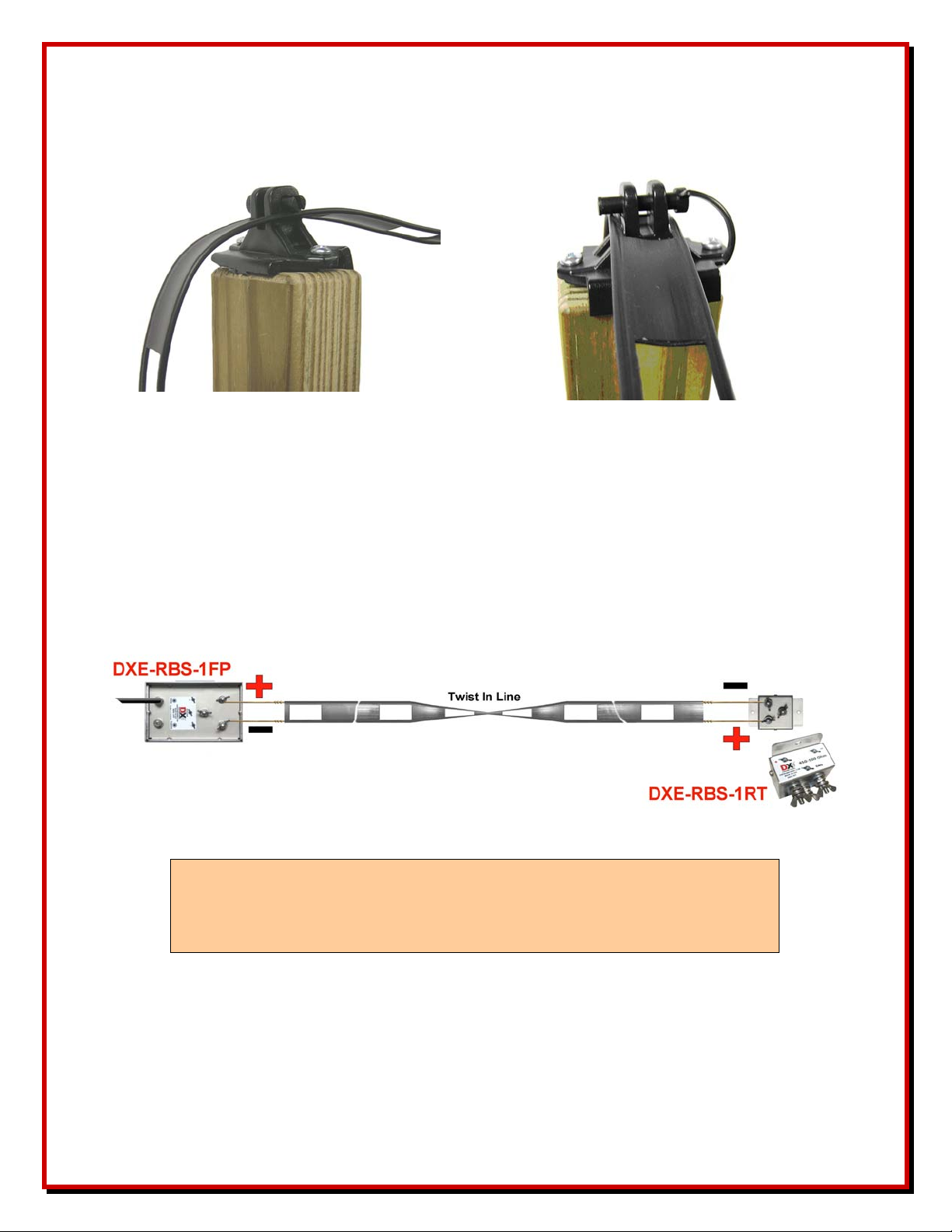
offers a very convenient insulator (See Figure 4) for securing the 450 ladder line to wood
supports. They also lock the line in place. Part number DXE-LL-INS includes 25 insulators.
The use of a non-conductive mounting configuration for the DXE-RBS-1FP and DXE-RBS-1RT
is also highly recommended. Use pressure treated posts or perhaps a handy tree. If mounting these
units on conductive supports (i.e., a metal fence post or pipe) keep the feedline a couple of inches
away from the support using non-conductive spacers as well. If a pipe is used to mount the DXE-
RBS-1FP Feed Point unit, use a V-Saddle clamp, part number DXE-CAVS-1P, that accepts pipe
sizes from 1/2” to 1-3/4”. The DXE-RBS-1RT reflection unit is flanged for mounting and requires
two wood or metal screws.
To enhance weather resistance of the DXE-RBS-1RT, it may be useful to put a bead of non
corrosive, marine grade silicone, like DX Engineering DXE-RTV598335,along the seams where
the two halves of the cases meet. Leave a small opening in the seams at their lowest point to allow
any condensation to drain. Silicone which contains acetic acid, which has a vinegar-like smell, is
corrosive to aluminum and should be avoided.
Ground Rods
A minimum of two, 5 foot, 3/4 inch OD or larger copper ground rods and clamps are required. One
rod is needed for each end of the antenna. In poor soil, adding an additional ground rod to each end
may improve performance. As an alternative, 3/4 inch OD copper water pipe works well.
Feedline
Use 75 coaxial cable with F-type coaxial cable connectors from the feed point unit to the
operating position. We recommend using a high quality 75 “flooded” RG-6 type coax such as DX
Engineering DXE-F6-SPL. Flooded style cables have the distinct advantage of automatically
sealing small accidental cuts or lacerations of the jacket. Flooding also prevents shield
contamination and the coaxial cable can be direct-buried. This coaxial cable is available with F-
Connectors installed and in any desired custom length from DX Engineering.
Preparing flooded F-6 cable for connectors not difficult with the correct tools. DX Engineering
offers an inexpensive stripping tool, part number DXE-CPT-659, that strips the F-6 coaxial cable in
one operation and the tool includes an extra cutting cartridge.
It is essential that the feedline connections are of high quality and weather resistant. The feedline is
used not only for the received signal, but also carries the voltage used for directional control. For

- 6 -
this reason, we recommend the use of Snap-N-Seal type F connectors. DX Engineering part number
DXE-SNS6-25 contains 25 Snap-N-Seal connectors.
The Snap-N-Seal connectors cannot be installed with normal crimping tools or pliers. An
installation tool like the DXE-SNS-CT1, available from DX Engineering, and is essential for proper
F type Snap-N-Seal connector installation.
Antenna Wire
A suitable length of balanced ladder or open wire line with an impedance between 300 and 600 .
See Table 1 for suggested lengths. The line that most closely approximates 450 impedance is #18
gauge. Ladder line constructed of #16 gauge wire, with standard 1-inch spacing, has about 420
impedance, but is considerably stronger, can use fewer supports and is less likely to break during
weather events. DX Engineering offers the #16 gauge ladder-line, part number DXE-LL450 in both
500 and 1000 foot spools.
Power Supply
Applying 9 to 12 Vac or negative 10 to 15 Vdc at 80 mA to the coaxial feedline will cause the
antenna to reverse receiving direction. The DX Engineering DXE-FVC-1 Feedline Voltage Coupler
which includes the required 12 Vac wall transformer can be used.
If using a Bias Tee, since a negative voltage is required for direction change, do not use a DC
source that is used for other station equipment; a separate wall transformer is recommended. The
source should be current limited or fused for no more than 1 amp. The DX Engineering DXE-PSW-
12D1A AC Adapter, 12Vdc 1000 mA Wall Transformer may be used, with the appropriate fusing
and polarity reversal handled before connection to a bias tee.
Installation
Site Selection
Like any antenna, the DXE-RBS-1 will couple to everything around it. This system should be
located more than a wavelength from other large metallic structures, such as towers or noise sources
like power lines, electric fence wires and neighbors’ houses in order to achieve peak performance.
Most installations involve compromise of some sort, so do the best you can.
The DXE-RBS-1 antenna is versatile in that you can make reasonable height changes, drape it over
tree branches (insulated balanced line only!), and deviate its path from a straight line by about 10
degrees without significantly degrading performance. Avoid placing the antenna near transmitting
antennas, power lines, large metal fences, or over buried cables. Install the balanced line 5 to 8 feet
above the ground. It is not necessary to strictly follow the contour of the land because small hills,
ravines and ditches generally will not affect the performance of the antenna.
While the impedance of the antenna is affected by its height above ground, the effect on
performance is minimal. A perfectly level (with respect to the ground) antenna looks better but is
not absolutely necessary!

- 7 -
Contrary to popular belief, a gradual slope of the antenna as it approaches its feed and termination
points does not improve performance. Simply bring the ends down to the termination and feed
boxes at any convenient angle, even if it is perfectly vertical. In the worst case the vertical portion
will be only a few feet. Signal reception in the few feet of wire comprising the vertical ends is
insignificant when compared to the signal reception from the entire length of the antenna. Unless
the antenna is more than 0.05-wavelength high, the vertical ends will not compromise antenna
performance.
Proximity to Transmitting Antennas
This system will not be damaged by a transmitted signal as long as it is more than 1/2-wavelength
from the transmitting antenna, and the power is not more than 1500 watts.
Do not transmit directly into this antenna with more than 10 watts.
Lightning Protection
This system features small air gaps and wide foil trace areas, as well as entrance gaps at all terminal
feed-throughs. The gaps act as safe, short paths for lightning. The DXE-RBS-1P is normally
immune to nearby lightning, although a direct strike might cause significant damage.
Figure 2
For additional lightning protection, use a 1-foot length of #26 wire between the antenna terminals
and each side of the balanced line, at both ends of the antenna as shown in Figure 2.
Grounding
The antenna GROUND terminals on both the feed and reflection units are intentionally insulated
from the metal enclosure and whatever the enclosure is mounted to. This isolation prevents the
feedline from becoming an unintentional ground path and introducing unwanted signals and noise
into the antenna system via a common feedline and antenna ground.
The shields of both the AWAY and TOWARD coaxial feedline connectors are common to the
DXE-RBS-1FP enclosure. Do not connect the DXE-RBS-1FP enclosure to the ground terminal,
since that would connect the feedline shields to the antenna ground and possibly increase noise or

- 8 -
reduce the front-to-back ratio. If you want to ground the metal housing, it should be grounded to its
own separate ground rod. That rod should be two to five feet from the nearest antenna ground.
Connect the ground terminal only to earth ground using at least one copper ground rod. Use a large
diameter ground rod when possible. We recommend using 3/4 inch OD or larger rigid copper water
pipe if possible, although conventional copper coated steel rods will also work. Avoid small
diameter ground rods. A good ground system improves performance and enhances lightning
survivability.
In poor conductivity soils, better performance may be realized with multiple ground rods spaced a
few feet apart. Remember that increasing ground rod depth beyond five feet rarely improves RF
grounding because skin effect in the soil prevents current from flowing deep in the soil.
Follow national and local wiring codes for grounding where cables enter a building.
Antenna
You will need at least 3/8-wavelength of a nominal 450 balanced ladder line for the antenna.
Ideally, the entire antenna run should be of the same type balanced line such as DXE-LL450-1K
450 Ladder Line. Mixing two similar appearing, but different impedance lines can compromise
system performance.
The performance difference between the various 450 lines is generally negligible, especially for
lengths near a multiple of 240 feet (73.1 meters) on the 160 Meter band, a multiple of 120 feet (36.5
meters) on the 80 meter band, or a multiple of 60 feet (18.2 meters) on the 40 Meter band. It is
possible to use home-made parallel line, although close spacing should be used.
The following combinations are examples of relative performance for various antenna lengths. The
antenna can be any length between 3/8-wavelength through multiple wavelengths. The DXE-RBS-
1P performance is excellent even when it is not cut to the ideal length.
Antenna Performance Based on Band / Length
Antenna Length 160 Meters 80 Meters 40 Meters 20 Meters
120 feet (36.5 meters) Too short Marginal Good Good
240 feet (73.1 meters) Marginal Good Best Good
360 feet (109.7 meters) Fair Best Best Good
480 feet (146.3 meters) Good Best Good Good
600 feet (182.9 meters) Better Good Good Good to Marginal
720 feet (219.4 meters) Best Good Good Marginal
Table 1 - Antenna Performance Chart
The DXE-RBS-1P is forgiving in many installation parameters. Nevertheless, attention to detail
will yield better performance.

- 9 -
Feedline
75 coaxial feedline from the DXE-RBS-1FP to the control voltage coupler and station is strongly
preferred, but any impedance from 50 to 75 ohms unbalanced is acceptable. We recommend using a
high quality 75 “flooded” RG-6 type coax such as DX Engineering part number DXE-F6-SPL.
Bury this feedline a few inches deep for 10 feet or more approaching the DXE-BS-1FP. Grounding
the feedline shield to a separate ground rod near the feedpoint may also be done, but is not
necessary. Use a 5-foot ground rod, but not the same ground rod used for the ground terminal on the
DXE-RBS-1FP. These two ground rods should be spaced a minimum of three to four feet apart.
If you use a single feedline, be sure the unused
port is terminated with the supplied termination
as shown in Figure 3. Failure to terminate the
unused port will significantly reduce the antenna
system's front-to-back ratio.
Figure3
Mounting
Feed Point and Reflection Units
The DXE-RBS-1FP feed point and DXE-RBS-1RT reflection units can be mounted on trees,
pressure treated lumber, or landscaping timbers. Pressure treated wood posts or landscaping timbers
are a convenient way to mount the units and also support and attach the ends of the antenna wire.
When setting end-posts, a power auger or post-hole digger works well. Line the hole with copper
flashing which will become part or all of the feed point (and termination) ground connection. If you
choose to use a metal pipe for mounting, use a DXE-CAVS-1P V-saddle clamp or other suitable
hardware. Do not use the metal mounting pipe for the antenna ground. Use a separate ground rod
placed at least two or more feet away from the base of the metal pipe. The DXE-RBS-1FP and the
DXE-RBS-1RT cases do not require grounding.
You may orient the feed point unit so the connectors labeled AWAY and TOWARD are at the
bottom and the antenna connections are at the top, but it is better if all connectors face downward.
Never mount this unit with the connectors facing up. The far-end reflection unit is normally
mounted with the two antenna terminals toward the top.
Antenna Ladder Line
The only requirement for the antenna wire support is it must hold the antenna up, and it can not
connect the antenna to ground. A metal pole with a small PVC stub for an insulator is every bit as
good as a full non-metallic pole. Trees make good supports, especially if you use electric-fence
insulators for use with wooden posts.
The support shown in Figure 4 can be nailed or screwed to either wood or plastic. The window in
the ladder line fits over the support and then a plastic pin locks it in place, while allowing it to float
horizontally. These DXE-LL-INS supports are available from DX Engineering, in packages of 25
insulators. The ladder line used for the RBS system may require more supports than a single wire

- 10 -
Beverage because of the limited tension you can apply to the wire, mainly due to the size of the
window in the line. The ladder line need not be perfectly parallel to the ground along its length, and
a half twist every 20 to 30 feet in the line will help maintain balance in the antenna.
Figure 4 - 450 ΩLadder Line Insulated Support
Connections
Antenna
The antenna ladder-line is connected between the feed point and reflection units observing the
polarity between the units. The + side of the ladder line on the feed point unit should be connected
to the +side of the reflection unit, refer to Figure 5. Since you may be twisting the ladder line
multiple times along its length, correct polarity should be verified using a meter. An incorrect
connection will result in poor front-to-back ratio or sensitivity.
Figure 5
Note: The antenna connection wing nuts on the units should be
hand tightened only, do not use any sort of pliers or other
tool as this places excessive force on the terminals.

- 11 -
Feedline
The factory-set configuration uses a single feedline, connected to the AWAY port, which is used for
the receive signal and to supply the reversing voltage to the DXE-RBS-1P.
The TOWARD port is terminated using the supplied terminating connector. With no reversing
voltage applied, the DXE-RBS-1P is responsive to signals coming from the far-end (AWAY)
direction as depicted in Figure 6. This is consistent with the receiving direction of a conventional
Beverage
The default receiving direction can be changed to the opposite direction (TOWARD) by moving the
terminating connector from the TOWARD port to the AWAY port and connecting the feedline to
the TOWARD port. Now the DXE-RBS-1P is sensitive to signals coming from the feed point end
or TOWARD direction with no reversing voltage applied. An internal jumper must also be changed
to allow the reversing voltage to be sent through the TOWARD port. Failure to change this internal
jumper will result in no directional reversing. Jumper selection is further discussed in the next
section.
Feedlines for both the AWAY and TOWARD ports can also be run back to the operating position.
This would allow receiving both directions simultaneously (requires two receivers) or the use of a
phasing unit for pattern modification or a noise attenuation device. No reversing voltage or jumper
changes are needed when using two feedlines.
Figure 6

- 12 -
Operation and Configuration
By default, with no reversing voltage applied, the DXE-RBS-1P is responsive to signals coming
from the far-end (AWAY) direction as depicted in Figure 6. When the reversing voltage (–12 Vdc
or 12 Vac) is continuously applied, the DXE-RBS-1P reverses direction. It now responds to signals
coming from the general direction of the feedpoint end (TOWARD) of the antenna. The TOWARD
port must be terminated using the supplied termination connector to ensure maximum front-to-back
and signal-to-noise ratio.
The default or un-switched receiving direction can be reversed by moving the feedline to the
TOWARDS port, moving the terminator to the AWAY port and by changing the internal header
jumper in the DXE-RBS-1P feed point unit to the TOWARDS side. This jumper determines which
port is used to supply the directional control voltage. This header jumper is set at the factory to the
AWAY port.
To access the jumper, remove 6 screws from the DXE-RBS-1FP unit and pull the cover out of its
housing. The jumper is located directly underneath the AWAY and TOWARD ports on the circuit
board. To change directional control to the TOWARD port, pull the small black jumper block
straight out, move it to the 2 pins closest to the TOWARD label on the circuit board. Always be
sure the jumper is installed with the notched end of the jumper block away from the circuit board.
Changing jumper position to the TOWARD port side is necessary only when the coaxial cable
supplying reversing voltage is moved to the TOWARD port. Be sure to terminate the unused port
with the supplied terminating connector.
Control Voltage
A negative 10 to 15 DC or AC voltage (AC contains negative voltage) must be continuously applied
to reverse the antenna receiving direction. The DX Engineering DXE-FVC-1 Feedline Voltage
Coupler which includes an AC wall transformer, couples this voltage to the coax feedline going to
the DXE-RBS-1FP.
Alternatively, a separate wall transformer may be used as the voltage source. Do not use a DC
source that is used for other station equipment; a separate wall transformer is recommended. The
source should be current limited or fused for no more than 1 amp such as the DX Engineering
DXE-PSW-12D1A AC Adapter, 12Vdc 1000 mA Wall Transformer.
Troubleshooting
The completed DXE-RBS-1P Beverage should exhibit a 1:1 SWR with 75 SWR meter, or
around 1.5:1 or slightly more with a 50 meter or antenna analyzer. Most of the antenna analyzers
available are 50 .
If you experience poor sensitivity, check the feedline connections, the polarity of the antenna ladder
line may be crossed, the antenna ground system may not be sufficient or may be improperly
connected (Refer to Figure 5). Do not ground the cases of the units to the antenna ground. The

- 13 -
Beverage length may also be marginal for the band, see Table 1 for suggested lengths. Make sure
the unused port is terminated.
If the DXE-RBS-1P directivity seems poor, ensure the jumper setting for directional control is on
the proper port. The jumper determines which port is used for directional control and should
coincide with the port used for the feedline. The DXE-RBS-1P requires a nominal –12 Vdc or AC
at the feed point unit to reverse direction. The sensitivity may also be marginal, see above.
The optional DX Engineering DXE-RPA-1 preamp may be used to provide up to 16 dB of gain to
the received signal if needed. Generally, if the DXE-RBS-1P produces enough signal to be heard
above the noise floor of the receiver, then the signal to noise ratio of the system will not be
improved with a preamp, it will just be louder. With the DXE-RBS-1P system, the DXE-RPA-1
must be installed at the operating position.

- 14 -
Additional Applications
Use two DXE-RBS-1P Reversible Beverage Systems, along with a DX Engineering DXE-RLS-2,
2-port receiving antenna switch, to build a four direction Beverage system using a single feedline.
See Figure 7. One or more DXE-RLS-2’s can be used to expand larger Beverage arrays and share
the feedline back to the operating position.
Figure 7 - Directional Beverage Layout - 4 Directions

- 15 -
Directional Beverage Layout
1. Single feed line from each DXE-RBS-1 to the DXE-RLS-2 and from the DXE-RLS-2 to
the receiver. The jumper in the DXE-RLS-2 must be reset for voltage pass through.
2. Uses voltage on the feedline to switch the DXE-RLS-2 and the DXE-RBS-1's.
3. DXE-RLS-2 switches when +12 Vdc is applied to feedline.
4. Port Selection Matrix:
Voltage Applied to
Feedline Selected Port
0 Vdc Beverage A, Away
-12 Vdc Beverage A, Toward
+12 Vdc Beverage B, Away
12 Vac Beverage B, Toward
Table 2 - Port Selection Control Voltage
5. The required DXE-FVC-1 applies the correct voltage to the feedline for a four direction
system. Controlling directions can be done with the DXE-CC-8 Control Console or a simple
ground closure arrangement using a 4-position rotary or other switch, with the internal
jumper reset in the DXE-FVC-1.
6. The DXE-FVC-1,DXE-CC-8 and DXE-RPA-1 pre-amp are normally located near the
receiver. The DXE-RLS-2 is normally located close to the DXE-RBS-1FP units as is the
DXE-RFCC-1 Feedline Choke to minimize the required feedline.

- 16 -
Optional Items
DXE-LL450-1K - Ladder Line, 450 ohm - 1000 ft. Spool - DXE-LL450-1K
DXE-LL450-5C - Ladder Line, 450 ohm - 500 ft. Spool - DXE-LL450-5C
Transmit-quality 450 ohm ladder line for your antenna project when the feedpoint impedance is close to 400 Ohms. It is also ideally
suited for use with our Reversible Beverage Antenna, the RBS-1P. This quality line is constructed of 16 gauge conductors that
are formed by 19 strands of 29 gauge copper-clad steel wire which provides the strength to hold up for long runs between supports.
Actual impedance is nominally 400 Ohms with a nominal velocity factor of 91%.
•1000' or 500' Spools
•Conductor AWG (strand): 16 (19/29)
•Nominal Impedance: 400 Ohms
•Velocity factor of 91%
DXE-LL-INS - 450 ohm Ladder Line Supports (25 per pack)
Top grade, UV stabilized, polyethylene ladder line supports designed for Beverage antennas that use 450 ohm line as the antenna
wire, like the DXE-RBS-1P.
•25 Per Pack
•Easy to install
•Molded Pin Holds Wire or Ladder Line Tightly – Simply pull the pin to release.
•Fits Standard Wood Posts
•Heavy Duty Flange Holds insulator to Post
•Top Grade, UV Stabilized Polyethylene Prevents Arcing and Provides Long Life
•5 Year Warranty
DXE-F6-CTL - 75 ohm F-6 Style Direct Bury Coax, Per Foot
DXE-F6-10000 - 75 ohm F-6 Style Direct Bury Coax, 1,000 Foot Spool
Hi Quality CATV, 75 Ohm F6 type "Flooded" Coax
Sold by the foot without connectors, specify length when ordering. Also available in a 1000 ft. Spool. Custom assemblies with
connectors are also available - call DX Engineering for details.
Center Conductor: 18 AWG Copper-Clad Steel, Nominal Diameter: 0.040 in., Dielectric: Gas Expanded
Polyethylene, Nominal Diameter Over Dielectric: 0.180 in. Shield: 1st Shield: Aluminum-Polypropylene-
Aluminum, Laminated Tape with overlap Bonded to the Dielectric, Nominal Diameter Over Tape: 0.187 in. 2nd
Shield: 34 AWG Aluminum Braid Wire, 60% Coverage. Jacket: PE (Flooded for Underground), Nominal Diameter
Over Jacket: 0.272 in., Nominal Jacket Thickness: 0.030 in. Electrical Properties: Impedance: 75.0 +/- 3.0 Ohms,
Velocity of Propagation: 85.0% Nominal . We recommend the use of Snap-N-Seal connectors to ensure a high
quality and weather resistant feedline connection. The proper tool must be used to install these connectors.
DXE-CPT-659
Prepares CATV F-6, RG-6 and RG-59 coax cable for the installation of an "F" type connector
•One-step cutting motion
•Precision cut
•No nicks or scratches to conductor
•Includes 1 replacement blade
DXE-CPT-659RB - Replacement Blades for DXE-CPT-659 Coax Cable Stripper, Package of 2
Replacement Blades for a DXE-CPT-659 Coax Cable Stripper, Package of 2

- 17 -
DXE-SNS6-25 - Watertight Coax Connector, Snap-N-Seal for CATV F-6 Cable, 25 pieces
Snap-N-Seal is an environmentally sealed CATV F coax connector system for harsh environments. The connectors have a unique,
360 degree radial compression system that offers the signal leakage protection required for high performance receive systems.
•Quad sealed system prevents moisture from migrating into the connection
•360 degree radial compression provides superior RF integrity (-95dB typical, 60% bonded foil cable)
•Easy cable preparation
•Connector to cable retention of 40 lbs minimum
•Superb impedance match to 1 GHz
•Manufactured of high quality 360 brass, cadmium plated with iridescent clear chromate coating for maximum corrosion
resistance
•UV-resistant plastic and O-rings provide a reliable environmentally sealed connector
An installation tool, such as the DXE-SNS-CT1, is required to install the connectors. Normal crimping tools or pliers will not work.
DXE-SNS-CT1 - Compression Tool for Snap-N-Seal 75 Ohm Coax Connectors
Ratchet compression tool for installing Snap-N-Seal 75 ohm Coax connectors. Ordinary pliers will not install these
connectors properly.
DXE-CAVS-1P - V-Saddle Clamp, 1/2 in. to 1-3/4 in. OD Applications
This V-Clamp is made in one size that fits tubing from 1/2 to 1-3/4'' OD as used in antenna construction. The supplied V-bolt is long
enough to attach tubing to thick plates and is made with anti-corrosive properties.
The as-cast rippled surface of the saddle will clamp the tubing securely to a flat surface; however, for high-torque
applications please use our standard U-bolt Saddle Clamps.
•Used to clamp 1/2 to 1-3/4'' (OD) tubing
•Designed for attachments that don't require resistance to torque
•V-bolt made from high-strength 18-8* stainless steel
•V-saddle cast from 535 aluminum with rippled surface
The use of an anti-seize compound is HIGHLY recommended to achieve proper torque and prevent galling.
These clamps are also available with a black power-coated saddle.
DXE-RTV598335 - Permatex Black RTV Sealant, Non-Acetic - 3.3 oz Tube, Black
DX Engineering Approved RTV Sealant - By Permatex. We have all used RTV to seal water out of things, right? Have you ever
sealed a piece of electronic gear with it -- then opened it some time later to find that it had still managed to
become corroded inside? Guess what? It's not the rain that corroded it - It's the RTV! Normal RTV gives off
acetic acid when it cures. That's the vinegar smell. The acetic acid causes the corrosion. DX Engineering has
located a Neutral Cure RTV made right here in Ohio that is non-corrosive and is safe for sealing those baluns and
other electronic gear that are going to be out in the weather. Applies just like "normal" RTV, dries in one hour
and cures in 24 hours at 70 degrees F. And it doesn't smell like vinegar!
•3.3 oz. Tube
•Black
*This part is classified hazardous and is limited to domestic UPS Ground shipping only

- 18 -
DXE-FVC-1 - Feedpoint Voltage Coupler
The FVC-1 provides an interface for standard control switches, such as the DXE-CC-8 or your own arrangement to voltage-
multiplexed antenna systems. This interface system will provide the voltages required to remotely select up to four antennas (or four
directions) through receiving or low power transmitting feedlines. It provides fuse-protected 0V, +12 Vdc, -12 Vdc, and 12 Vac.
output voltages through a panel mounted feedline connector. These voltages can be used to provide four-direction switching of an
antenna array either through the feedline or on a single wire supplemental control line. Control is done using a standard 1 of 4, BCD
or switch closure interface(internal jumper selectable).
The FVC-1 is recommended for use with the RBS-1 Reversible Beverage Antenna System , and the RLS-2 Transfer Switch . The
CC-8 Control Console can provide the 1 of 4 and BCD input used by the FVC-1 or you can use your own switch.
The FVC-1 also has two LED indicators, red and green, which indicate the presence and polarity of the output control voltage being
used. They are directional indicators that can be read at a convenient distance and can aid in troubleshooting. Features
•Safe, external 12V heavy duty power pack.
•Metal Housing – superior shielding, rugged, and easy mounting
•Convenient installation– mounts anywhere in your shack
•Rugged Control Connector – reliable solder-less connections
•Internal thermal reset fuse- full protection against accidental shorts
•Flexible logic input- BCD or standard one-of-four, high or low actuated
•Operation indicators- bright red and green LED indicators can be seen at a distance
DXE-RPA-1 - Receiver Preamplifier, 0.3-35 MHz
This is the best HF low noise amplifier available. The RPA-1 is optimized for 0.3-35 MHz operating range. The push-pull amplifier
design and robust components enable it to withstand high signal levels and operate when you need it most. The dynamic range of the
RPA-1 is better than most receivers. The RPA-1 is suitable for indoor or outdoor installation, with the option of being powered
through the coaxial feed. The metal housing provides shielding and improved lifespan. The unit uses RCA type phono jack and
CATV F connector for the input and output connections, and has a relay that automatically bypasses the amplifier when dc power is
removed.
Benefits:
•Push-pull operation eliminates harmonic distortion
•High quiescent current increases ability to handle strong signals without distortion or overload
•Meticulous craftsmanship and durable components provide superior dynamic range
•RCA type phono jack and type F connector ease installation
•Simplified switching - automatic bypass eliminates gain when dc power is off
•10-18 Vdc power using power connector or through the coax
•10-18 Vdc through coax enables remote operation at antenna
DXE-RFCC-1 - Receive Feedline Current Choke, 50 to 75 Ohm 300 kHz to 30 MHz
If you wish to reduce signal pick up and improve reception, a Receive Feedline Current Choke is recommended. Adding a DX
Engineering Receive Feedline Current Choke at the point where the feedline exits the area of the antenna will substantially reduce
unwanted feedline reception without the need for improved station grounding.
The advantages of using an RFCC:
•Prevents unwanted RFI reception by eliminating feedline current
•Reduces noise or unwanted signals picked-up by the feedline
•Overcome a less than optimal ground system
The DX Engineering RFCC-1 receive feedline common-mode choke is the most effective solution to
common-mode noise or unwanted signal ingress available to date. The DX Engineering RFCC-1 provides thousands of ohms
isolation between the input and output coaxial shield connections while passing desired signals, including dc or low frequency ac
control signals. The RFCC-1 has extremely high isolation impedance which effectively blocks common-mode noise or unwanted
signals, even in the presence of very poor grounding. Low noise receive antennas are traditionally located away from electrical
wiring and other noise sources. Unfortunately, noise and other unwanted signals have a direct path to your low-noise antenna through
the feedline shield connections between the station equipment and antenna. Unwanted signals can also energize the outside of the
feedline shield, and this undesired signal energy can be conducted directly to the receiving antenna. This can reduce antenna
directivity. Unless you have a perfect zero-resistance RF ground at the antenna, some of the common-mode noise or unwanted
signals from the feedline shield will make it into the antenna. The RFCC-1 is effective from 300 kHz to 30 MHz. It comes with
standard CATV type “F” female connectors, although it can be used in any 50 to 75 ohm receiving system. The RFCC-1 is a passive
device, therefore requires no power to operate.

- 19 -
DXE-CC8 - CC-8 Control Console, 8 Position
The CC-8 Control Console is a flexible, 8-position controller used to control the DX Engineering RR8 series antenna switches, the
RFS-2 Receive Four Square controller or any product that uses a 12 or 24 Vdc 1-of-8 or BCD control format. The attractive metal
housing is powder-coated and features an ON/OFF switch, ergonomic selector knob and eight front-panel LED's, with adjustable
brightness, to indicate switch position. The rear panel external plug allows the control cable to be easily unplugged during weather
events or if the shack needs to be rearranged. We suggest unplugging the CC-8 control leads when severe weather is expected. The
use of a lightning protector on the control lines, such as the PolyPhaser PPC-IS-RCT, available from DX Engineering, is prudent as
well. Shielded CAT-5 type cable can be used for the control cable. (8 conductors plus ground) . The internal AC power supply is
jumper selectable for 110-130 or 220-260 Vac input. Output control voltage is jumper selectable for 12 or 24 Vdc.
Features
•Switching positions: 8
•Input voltage: 120/240 Vac, 50/60Hz (jumper selectable)
•Output voltage: 12 Vdc @ 1.5A or 24 Vdc @ 0.75A (jumper selectable)
•Protection: Dual internal automatic reset fuses
•Output format: 3-bit BCD or standard 1-of-8
•Dimensions: 8 x 5 x 2.75'' (203.2 x 127 x 69.85 mm) (W x D x H)
DXE-RLS-2 - Two Port Receive Antenna Switch
The DX Engineering 2-Port Receiving Antenna Switch RLS-2 is designed to allow selection of one of two output ports (generally
connected to different receiving antennas) from one feedline. Transfer activates with application of a +10-15 Vdc or 9-12 Vac control
voltage through the feedline.
Features
•Metal housing for superior shielding and long life
•High quality components
•Reliable F-type connectors
•Operating range from 300 kHz to 30 MHz with 75 systems
•Jumper-selectable, control voltage pass-thru to the selected port
When used with two DX Engineering RBS-1 Reversible Beverage Systems, the RLS-2 will allow selection of four directions using a
single main feedline. Install one or more RLS-2’s to expand larger Beverage arrays and share the feedline back to the operating
position. The DX Engineering FVC-1 Voltage Coupler can be used to supply the control voltages through the feedline to control 4-
direction switching of an receiving array (using two RLS-2's) or selection of four different receiving antennas.
DXE-PSW-12D1A AC Adapter 12 Volt DC 1000 mA Wall Transformer
110 Vac 60 Hz input - 12 Vdc, 1 Amp, Fused output. A standard 2.1 mm plug connection for 12 Vdc.
Outer connection is GROUND Center Pin is input for +12 VDC.
DXE-CW9 - Shielded Control Wire, 9 conductor, per foot
DXE-CW9-1K is a high quality shielded outdoor FTP (Foil Twisted Pair) CAT 5e cable. It features 4 Twisted pairs
of 24 AWG solid wire with Al foil shielding plus a solid tinned copper drain wire - providing a total of 9 conductors
for DC switching applications. It has a polyethylene jacket and is rated for direct burial. This cable is ideal for DX
Engineering Remote Antenna Switches and Four Square arrays, and should be considered for any low-current
custom remote switching application you have - such as receiving antenna arrays. Order by the foot in the length you
require. A nice feature is the "rip cord", which allows for easy stripping of the heavy jacket without worry about
nicking or accidentally cutting the conductors. Excellent for use in all outdoor applications of switching, networking,
data transfer and phone lines. As a data transfer line, it supports 10/100/1000Mbps.
DXE-CW9-1K - Shielded Control Wire, 9 conductor, 1000 ft reel
DXE-CW9-1K is a 1000 foot box of high quality shielded outdoor FTP (Foil Twisted Pair) CAT 5e cable. It
features 4 Twisted pairs of 24 AWG solid wire with Al foil shielding plus a solid tinned copper drain wire -
providing a total of 9 conductors for DC switching applications. It has a polyethylene jacket and is rated for direct
burial. This cable is ideal for DX Engineering Remote Antenna Switches and Four Square arrays, and should be
considered for any low-current custom remote switching application you have - such as receiving antenna arrays.
A nice feature is the "rip cord", which allows for easy stripping of the heavy jacket without worry about nicking or
accidentally cutting the conductors. Excellent for use in all outdoor applications of switching, networking, data
transfer and phone lines. As a data transfer line, it supports 10/100/1000Mbps.

- 20 -
Technical Support
If you have questions about this product, or if you experience difficulties during the installation,
contact DX Engineering at (330) 572-3200. You can also e-mail us at:
For best service, please take a few minutes to review this manual before you call.
Warranty
All products manufactured by DX Engineering are warranted to be free from defects in material and
workmanship for a period of one (1) year from date of shipment. DX Engineering’s sole obligation under
these warranties shall be to issue credit, repair or replace any item or part thereof which is proved to be other
than as warranted; no allowance shall be made for any labor charges of Buyer for replacement of parts,
adjustment or repairs, or any other work, unless such charges are authorized in advance by DX Engineering.
If DX Engineering’s products are claimed to be defective in material or workmanship, DX Engineering shall,
upon prompt notice thereof, issue shipping instructions for return to DX Engineering (transportation-charges
prepaid by Buyer). Every such claim for breach of these warranties shall be deemed to be waived by Buyer
unless made in writing. The above warranties shall not extend to any products or parts thereof which have
been subjected to any misuse or neglect, damaged by accident, rendered defective by reason of improper
installation, damaged from severe weather including floods, or abnormal environmental conditions such as
prolonged exposure to corrosives or power surges, or by the performance of repairs or alterations outside of
our plant, and shall not apply to any goods or parts thereof furnished by Buyer or acquired from others at
Buyer’s specifications. In addition, DX Engineering’s warranties do not extend to other equipment and parts
manufactured by others except to the extent of the original manufacturer’s warranty to DX Engineering. The
obligations under the foregoing warranties are limited to the precise terms thereof. These warranties provide
exclusive remedies, expressly in lieu of all other remedies including claims for special or consequential
damages. SELLER NEITHER MAKES NOR ASSUMES ANY OTHER WARRANTY WHATSOEVER,
WHETHER EXPRESS, STATUTORY, OR IMPLIED, INCLUDING WARRANTIES OF
MERCHANTABILITY AND FITNESS, AND NO PERSON IS AUTHORIZED TO ASSUME FOR DX
ENGINEERING ANY OBLIGATION OR LIABILITY NOT STRICTLY IN ACCORDANCE WITH THE
FOREGOING.
©DX Engineering 2009
DX Engineering®, DXE®, Hot Rodz™, Maxi-Core™, THUNDERBOLT™, Antenna Designer™, Yagi
Mechanical™, and Gorilla Grip™ Stainless Steel Boom Clamps, are trademarks of PDS Electronics, Inc. No
license to use or reproduce any of these trademarks or other trademarks is given or implied. All other brands
and product names are the trademarks of their respective owners.
Specifications subject to change without notice.
Table of contents
Other DX Engineering Industrial Equipment manuals