DX DXE-TFS4-160B User manual

Transmit Four Square System
Phasing Unit and Four Square Control Console
DXE-TFS Series for 160, 80 or 40 Meters
DXE-TFS4-160B, DXE-TFS4-80B, DXE-TFS4-40B
DXE-TFSB-INS Revision 1a
© DX Engineering 2013
1200 Southeast Ave. - Tallmadge, OH 44278 USA
Phone: (800) 777-0703 ∙ Tech Support and International: (330) 572-3200

2
Table of Contents
Introduction
3
System Overview
3
Features
4
Required Parts Not Included
5
System Discussion
5
Vertical Antenna Selection
7
Warning
8
Overhead Power Line Safety
8
Installation
9
Suggested Installation Sequence
9
Site Selection
9
The Four Square Layout
9
Topographical Considerations
12
Site Selection in Relation to Noise Sources
12
Mounting the Four Square System Phasing Unit
13
Antenna Feedline
14
Control Wire Connections
16
Radial System
17
Tuning the Vertical Antennas Radial System
19
Four Square Control Console Front Panel
20
Four Square Control Console Direction Label
21
Four Square Control Console Rear Panel
23
Four Square System Phasing Unit Connections
25
Typical Transceiver / Amplifier Connections
26
Lightning Protection
27
Turn On and Test
27
Power ON Relay Exercise
27
LED Brightness
28
Using the Transmit Four Square System Phasing Unit
28
Manual Updates
29
Optional Items
29
Technical Support and Warranty
32
Tables and Figures
Table 1
DX Engineering Monoband Vertical Antennas
7
Table 2
Four Square Vertical Antenna Spacing Chart
10
Table 3
Radial Wire Lengths for 160, 80, 75, and 40 Meters
17
Table 4
Four Square Control Logic
24
Figure 1
Four Square Antenna System Layout
11
Figure 2
Mounting the Four Square System Phasing Unit
14
Figure 3
Electrical Length Feedlines
15
Figure 4
Control Wire Connections from the Control Console to
the Four Square System Phasing Unit
16
Figure 5
Typical Radial Field
18
Figure 6
Cross Bonding the Radial Field
19
Figure 7
Four Square Control Console Front Panel
20
Figure 8
Four Square Control Console Rear Panel
23
Figure 9
Four Square System Phasing Unit Connections
24
Figure 10
Typical Transceiver / Amplifier Connections
26

3
Introduction
System Overview
DX Engineering's TFS4 series of Transmit Four Square System Phasing Units bring together the
highest level of engineering excellence with the practical realities of operator convenience and ease
of installation.
The Transmit Four Square Series System Phasing units are currently available only in monoband
versions for either the 160, 80/75 or 40 meter bands. Check DXEngineering.com for the latest
models.
DXE Model
Band of Operation
DXE-TFS4-160B
160 Meters
DXE-TFS4-80B
80/75 Meters
DXE-TFS4-40B
40 Meters
The DX Engineering Transmit Four Square series System Phasing Unit is easily dropped into your
quarter-wave spaced vertical 4-square array to provide optimum directional control.
The system will allow the operator to receive or transmit with gain in any one of four directions
with good front-to-back ratio, or in a single high efficiency omni-directional pattern with a push of a
single button. This combination is a great tool which permits you to transmit and listen "all-around"
unhindered by pattern nulls, and then select the best direction for signal reception and noise
rejection.
The standard four square array uses four ground mounted 1/4-wave vertical antennas positioned at
the corners of a square land area that measures 1/4-wavelength on a side. The antennas must be
located as described in the installation section to provide switchable patterns in desired directions.
The forward lobes are reasonably wide eliminating the need for precise aiming while also providing
coverage of in-between directions.
The four vertical antennas must be resonant in the desired band of operation. Each vertical element
must be directly fed through 1/4-wave long 75Ωtransmission lines. Do not use additional matching
components or decoupling devices like baluns or coils between the centrally located Four Square
System Phasing Unit and the verticals, as additional transmission lines can reduce array
performance. The vertical antennas must be series-fed at the base. The verticals must be 1/4-wave
long or electrically 1/4-wave and must be resonant. DX Engineering offers vertical antennas that are
well suited for this application. Above all, a properly designed and installed radial system is
necessary for maximum system performance. Detailed information of the entire array follows in the
installation section.
The four 30-40 Ωfeedpoint vertical antennas are connected to the Four Square System Phasing Unit
by electrical 1/4-wavelength 75Ω cables foam dielectric cables. Coaxial cable velocity factor must
be high enough to allow the cable to physically reach the Phasing Unit. The recommended coaxial
cable for this application is DXE-11U. This is an RG-11/U type foam dielectric cable with a

4
velocity factor of 84% (0.84). During phased array operation, due to mutual coupling, each vertical
antenna has a different operating impedance. This means transmitter power is not evenly divided by
the Four Square System Phasing Unit. The highest effective power into any element feed cable is
approximately half of the applied power, which means the overall system can handle approximately
twice the 1:1 SWR 75Ω cable ratings when used in this application. Properly prepared 1/4-wave
cables may be ordered from DX Engineering Customer Service.
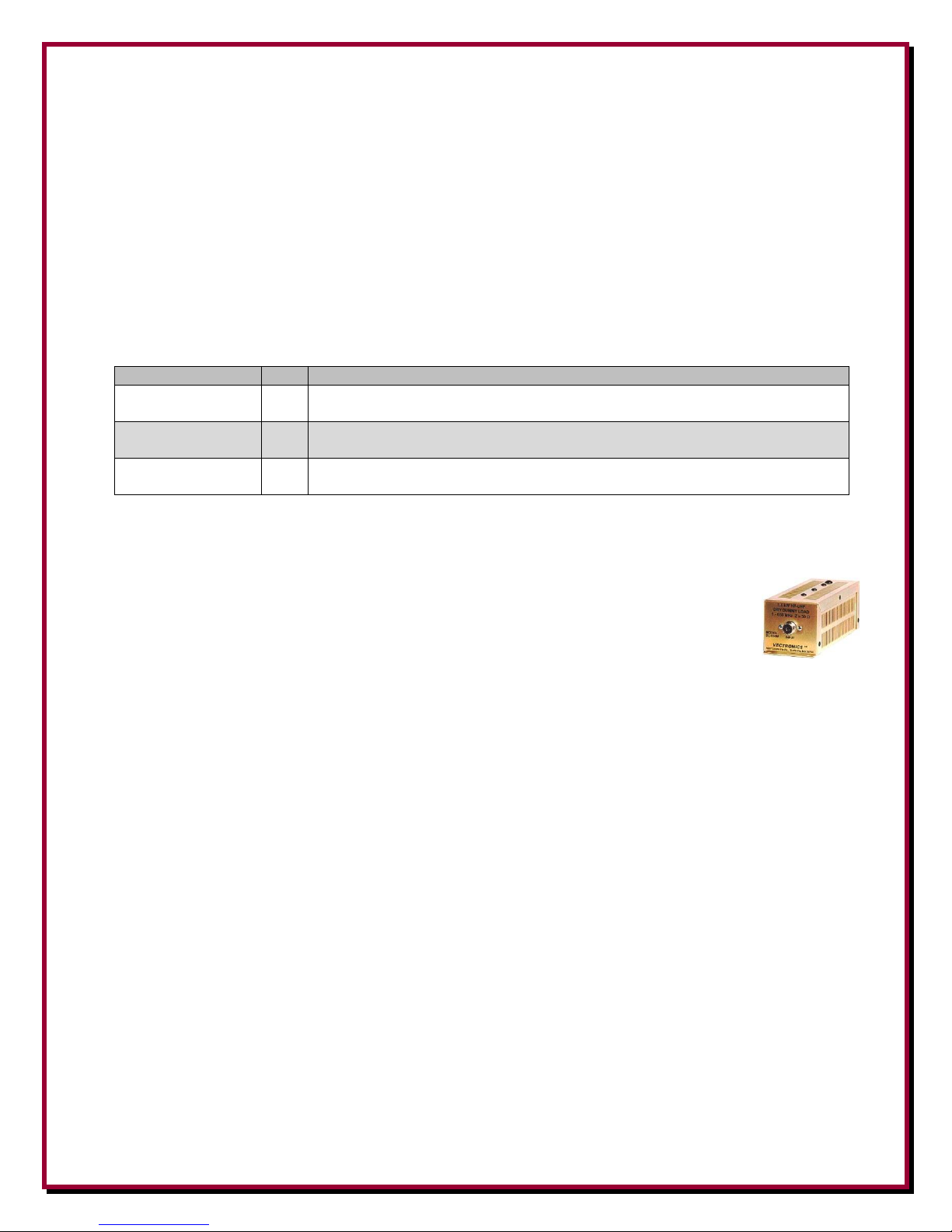
If you already have a four square array with a Comtek or similar hybrid controller and would like to
improve overall performance, add the power handling capability and Omni feature of the DX
Engineering TFS4 Transmit Four Square Series, which is essentially a direct replacement system. A
slight shift downwards in optimum performance frequency may result from this substitution.
Control is accomplished using a four-wire control cable to perform all the necessary switching
functions when connected to the included DXE-CC-4SQR Transmit Four Square Control Console.
Optional DXE-CW9 CAT 5 control cable is available from DX Engineering. Push-button switching
allows instantaneous direction change. Your amplifier keying or relay line should be routed through
the control console. This prevents catastrophic failures caused by relay transfer while the amplifier
is activated. The DXE-CC-4SQR Control Console allows you to call for pattern changes while
transmitting without damaging relay contacts.
Features
Four Directions PLUS Omni - versatile operation
5 kW CW Power Rating - high reliability
10 kW PEP SSB
Hot switching lockout - disables amplifier during directional changes
Drop-in replacement for Comtek - easy upgrade
Proven DX Engineering RF Relays - high performance
RF Shielded Weatherproof Housing - unique protection
Custom label with four compass direction sets for the Control Console
Relays cycle during Power-On
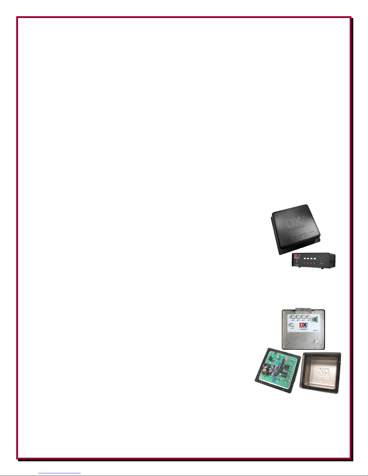
The DX Engineering Transmit Four Square system consists of a Transmit Four Square Control
Console that has four momentary contact light-touch push-button
switches for direction control and one push-button for omni selection.
There is a toggle switch for power on/off, and four variable brightness
green LEDs (light emitting diodes) to show the system's current
direction. A custom label for the Control Console to indicate four
antenna directions. During Omni operation, all four LEDs light at the
same time. A 2.1 mm DC power cord is supplied with the unit.
The custom made Four Square System Phasing Unit must be located at
the center of the four square antenna system. Also included is a DXE-
SSVC-2P V-Clamp for mounting the Four Square System Phasing Unit.
Note: UMI-81343 Never-Seez®or DXE-NSBT8 Anti-Seize should be
used on all clamps, bolts and stainless steel threaded hardware to prevent galling and to ensure
proper tightening.

5
Required Parts Not Included with the TFS4 Series
Four quarter-wave resonant vertical antennas for your selected band
Four DXE-RADP-3 Radial Plates plus extra DXE-225RT-20 Ring Terminal Kits and DXE-
RADP-1HWK Radial Plate Wire Attachment Hardware Kits
Four DXE-SSVC-2P V-Clamps - One for mounting each of the four DXE Radial Plates
DXE-RADW - Bulk radial wire and kits
Radial Cross Bonding Copper Strap - DXE-CS2-100
Coaxial Cable - 75 Ω- DXE-11U foam dielectric (or equivalent)
Single replacement, or sets of four, custom made 1/4 electrical wavelength cables with PL-
259 connectors are available from DX Engineering:
Part Number
Qty
Description
DXE-Q75-160-4P
4
1/4 Electrical Wavelength 160 meter 75 Ωcoaxial cables with PL-259 connectors
on each end. Customer to specify center frequency.
DXE-Q75-80-4P
4
1/4 Electrical Wavelength 75/80 meter 75 Ωcoaxial cables with PL-259 connectors
on each end. Customer to specify center frequency.
DXE-Q75-40-4P
4
1/4 Electrical Wavelength 40 meter 75 Ωcoaxial cables with PL-259 connectors on
each end. Customer to specify center frequency.
Control Cable - DXE-CW9 CAT 5 UV resistant (or similar)
Dummy Load - 50 Ω- 200 Watts or greater and 50 Ωfeedline for the dummy load.
A Vectronics DL-650M Dummy Load is available from DX Engineering.
The VEC-DL650M Dummy Load simulates an accurate 50 Ωantenna up to
650 MHz, enabling you to test your transmitter without radiating a signal on
the air. DC to 650 MHz. Handles short-term RF power up to 1500 watts.
Dummy Load coaxial cable is available in any custom length with PL-259
connectors attached. Call DX Engineering for custom lengths of either RG-8X or RG-8U
System Discussion
A four-square antenna array is a single band directional antenna system. It uses four current-fed
vertical antennas positioned at the corners of a 1/4-wavelength on a side square. In order to produce
deep nulls each element must have equal currents and proper phase shift. Each element is excited
through a 1/4-wave 75 Ωfeedline. The unique characteristic of a 1/4-wave transmission line is that
equal voltage at the source end will always produce equal currents at the load end, and the net phase
shift will always be constant regardless of line SWR. This unique combination is not true for any
other length of transmission line, except a very low-loss line that is an odd 1/4-wave long. The 75 Ω
line, since it is mismatched at the antenna, also transforms the impedance of the element.
The Four Square System Phasing Unit contains unique circuitry that, in combination with the
transmission lines to each element, cancels reactance and supplies each feedline with approximately
equal voltage and near ideal phase shift.
The TFS4 series Four Square System Phasing Unit provides four switchable unidirectional cardioid
patterns, along with the unique addition of a switch selection for an omni-directional pattern.

6
The SWR bandwidth and directional performance bandwidth of this system is highly dependent
upon the characteristics of the vertical elements used in the array. The Four Square System Phasing
Unit is a switchable modified hybrid coupler. It provides proper currents and phase at each antenna
element when the correct electrical length 75 Ωfeedlines to each vertical antenna are used.
Each of the four vertical antennas used in the Transmit Four Square system must be very similar to
each other. If the elements have different impedances or radiation characteristics, system
performance will suffer.
Each side of the square must be 1/4-wavelength in free space at the desired operating frequency. For
example, each side must be 64.7 ft for a center frequency of 3.800 MHz.
Note that the free space formula 246/f (MHz) is used for array spacing - not the more familiar 234/f
(MHz) used for antenna element lengths, which takes element end effect into account.
Array spacing is important in providing the deepest rear null –commonly observed when checking
the front-to-back ratio (F/B).
The TFS4 Four Square System Phasing Unit is placed in the physical center of the square, where
exactly equal 1/4-wavelength 75Ω coaxial cables connect each vertical element to the Four Square
System Phasing Unit. Note that the cable lengths are different from the free space length of the
square sides. This is because the cables have a different velocity factor than air. Radio frequency
signals move through the cables slower than they move through air.
For best performance, you should install a good ground radial system. 32 straight radials, most
about 1/4 wavelength long, are recommended at each of the four vertical antennas. Some of the
radials will cross in the middle of the array. These radials may be allowed to cross if well-insulated
from each other at crossing points, but it is better if they are bonded as described in the installation
section. Either method will provide suitable performance. What cannot be tolerated are poor or
intermittent connections between radials.
As with any properly installed quarter-wave vertical antenna, signals arriving at lower angles of
radiation will be enhanced more than very high angle signals. Phasing is optimized for very low
wave angles. This means array directional performance will generally be better on more distant low
angle and on local ground-wave signals.
While greatly dependent on many variables, (such as the radial system, angle of arrival of signals,
etc.), the gain of a properly designed and installed four-square array will be on the order of 5 dB
over a single vertical element.
Typical F/B ratios will approach or exceed 20 dB, minimizing interference from the side and rear
directions. See various reference books such as "ON4UN’s Low Band DXing" for more in-depth
discussion of four-square theory and performance.

7
Vertical Antenna Selection
To provide optimum performance four vertical antennas of identical design are required. Each of
the four vertical antennas used in the Transmit Four Square must be identical. If not, peak
performance may not be obtainable. The vertical antennas must be spaced in a square according to
wavelength and have good radial systems installed. Anything less could cause serious performance
degradation.
The following DX Engineering monoband vertical antennas are an ideal match for top performance
in a four square array system.
DXE-40VE-1
DXE-40VA-1
EZ-UP
DXE-80VA-3
THUNDERBOLT
DXE-ATK65 and
DXE-VE BASE
Band
40
40
80 or 75
80 or 75
Taper
Fast
Slow
Slow
Fast
Element Size Range
2" to 1/2"
2" to 1-3/8"
2-1/8" to 1-1/2"
2" to 7/8"
Height
33-35'
<24'
43'
64'
Guying
Suggested
Suggested
Required
Required
Capacitance Hat
no
yes
12' dia (Included)
no
DXE-80VA-3 : Do not use shunt coil
Table 1 - DXE Monoband Vertical Antennas
Fast Taper - Slow Taper: Fast Taper uses smaller diameter aluminum elements for
less wind resistance. Slow Taper uses larger diameter aluminum elements for sturdy
construction and wider bandwidth.
For those that want to design and build their own vertical antennas, DX Engineering also has the
parts needed to accomplish this task.
The DXE-ATK65 Telescopic 65 Foot Aluminum Antenna Kit comes with 11 slow taper, 6 foot
sections, and one 3 foot section of DX Engineering rugged 6063-T832 aluminum tubing and all-
stainless steel element clamps. The bottom section is heavy wall 2 inch OD graduating up to 2-1/8
inch and back to 2 inch for the first 12 feet. The sections then taper to 7/8 inch OD at the top. When
coupled with the DXE-VA-BASE -Heavy Duty Vertical Antenna Tilt Base Assembly,
the DXE-ATK65 is ideally suited as a vertical radiator for your custom-designed antenna system -
singly, or as a Four Square or other multiple antenna arrays. It can be set to any length up to 65
feet by simply removing or telescoping the sections and clamping at the desired length. Additional,
smaller diameter 6-foot telescoping aluminum tubing sections are available from DX Engineering.
For heavy duty applications, the DXE-VA-BASE Insulated Vertical Antenna Base with its
supplied laser cut stainless steel Tilt Base, and complete stainless steel hardware package is
intended to support a 2 inch OD antenna base section in a vertical position and to allow tilting
for easy maintenance or tuning. The DXE-VA-BASE is designed for vertical antennas that
exceed 30-35 feet. The DXE-VA-BASE consists of a unique reinforced fiberglass insulating
channel which has twice the strength of commonly used nylon and other insulating materials. It
is fastened with stainless steel hardware to a rugged 3/16 inch thick stainless steel laser cut Tilt
Base. With a DX Engineering Tilt Base, operators can raise or lower their vertical antenna in
seconds while leaving the base plate securely attached to the mounting pipe or post. One person can

8
service the antenna. No more climbing ladders or removing brackets. Easily make repairs, tune your
vertical or lay your antenna down before bad weather hits. The Tilt Base may be bolted to a secure
flat mounting surface, or to the recommended galvanized steel mounting pipe described in the
installation instructions with two optional DXE-SSVC-2P Stainless Steel V-Clamps.
For operation on 160 meters, the customer must supply the four vertical 160 meter resonant antenna
system. There are a number of vertical resonant designs available for operation on 160 meters. See
various reference books such as “ON4UN’s Low Band DXing”,the “ARRL Antenna Book”or other
reliable text for details.
WARNING!
INSTALLATION OF ANY ANTENNA NEAR POWER LINES IS DANGEROUS
Warning:Do not locate the antennas near overhead power lines or other electric lighting or
power circuits, or where they can come into contact with such circuits in the event of an accident or
mechanical failure. NEVER INSTALL AN ANTENNA WHERE IT CAN FALL INTO OR
ACCIDENTALLY TOUCH a power line. Very serious injury or death can result from contact with
utility lines.
Overhead Power Line Safety
Before you begin working, check carefully for overhead power lines in the area you will be
working. Don't assume that wires are telephone or cable lines: check with your electric utility for
advice. Although overhead power lines may appear to be insulated, such coverings are not intended
to nor can they be relied on to protect you from electrocution.
Keep your distance! Remember the 10-foot rule: When carrying and using ladders and other long
tools, keep the falling distance at least 10 feet away from all overhead lines - including any lines
from the power pole to your home. Your local utility will advise you if an antenna location is safe
or not.

9
Installation
Suggested Installation Sequence
Site Selection
Antenna Selection
Mounting post installations
Feedline and control cable installation
Radial System Installation
Antenna Installation and tuning
System phasing unit installation
Coaxial Cable and control wire connections
Testing and operation
Site Selection
Select a mounting location clear from power lines, structures and other antennas. Pay special
attention to overhead power lines, utility cables and wires. Vertical antennas should be mounted
well away from local noise sources or large metallic objects that might re-radiate noise and affect
the tuning, radiation pattern or SWR. When using the DX Engineering Tilt Base, determine the
direction you want the antenna to tilt down and make sure there is adequate clearance. There should
also be a clear area for guying and radial systems extending away from the four antennas.
The Four Square Layout
The four monoband vertical antennas making up the four-square system must be properly
positioned. You must adhere to the dimensions shown in Table 2 for optimum performance. The
placement of the four vertical antennas in relation to each other is somewhat critical. If more than
five percent out of specification, system performance can suffer. The formula for determining the
distance between each antenna (1/4-wavelength) is:
246
L in Feet =
▬▬▬
MHz
For four square arrays use 246 divided by the Frequency in MHz = Length in feet
Other spacing close to this value may work, but the characteristics of the main lobe will change
gain, directivity and front-to-back. Time spent in laying out a symmetrical installation will pay solid
dividends. The system is forgiving, but the best front-to-back is obtained when symmetry is
maintained and with each element resonant on the same frequency and with each antenna base at
the same elevation.

10
The following chart shows various calculations depending on the desired center frequency. The
frequencies shown here are various CW, DX, and SSB frequencies used in the American Radio
Relay League Band Plan:
Band
(Meters)
Typical Center
Frequency
(MHz)
Distance between antennas
(1/4-wavelength)
at the Center Frequency
Meters
Feet
160
1.830
41.0
134.4
1.845
41.0
133.3
1.950
38.5
126.2
80/75
3.550
21.1
69.3
3.560
21.1
69.1
3.575
21.0
68.8
3.650
21.0
67.4
3.710
20.2
66.3
3.795
20.0
64.8
3.985
19.0
61.7
40
7.030
11.1
34.9
7.040
11.0
34.9
7.110
11.0
34.6
7.150
10.4
34.4
7.225
10.3
34.0
Table 2 - TFS4 Four Square Vertical Antenna Spacing

11
Looking at the bottom of the
Four Square System Phasing Unit
Antenna Layout - Top View
The four vertical antennas are arranged in a
square 1/4-wavelength on a side.
The four square array is directional across its
diagonals.
The Four Square System Phasing Unit is located
in the center of the square. Connections from the
Four Square System Phasing Unit to the antennas
must be equal 1/4 electrical wavelength 75 Ω
coaxial cable lines as described in the Antenna
Feedline section of this manual.
Top View - Radial Field
Figure 1 - TFS4 Four Square - Antenna System Layout

12
Topographical Considerations
Flat or gradually sloped land is best. Erecting the transmitting array on steeply sloped land or
uneven terrain might degrade performance. To avoid pattern degradation, antenna elements should
have reasonably similar elevations. It's recommended the maximum ground height difference
between any of the vertical antennas in the array should be less than 20% of the array diameter. For
example, a 64 foot square array should be within 12 feet of level. Every effort should be taken to
make the elements symmetrical. Elements should be very similar or identical in construction and
grounding. Elements should be mounted above any standing water or snow line, but as close to the
ground as possible. In general, the system will not be affected by trees or foliage so long as the
foliage is not near an element. The open ends or tips of the elements are particularly sensitive to
close branches or foliage. There should be a reasonably clear electrical path for at least 1
wavelength in important receiving directions. The site should allow a radial system to be as evenly
distributed around each of the vertical elements as possible, although perfect symmetry isn’t
important so long as the radial connections are good.
Most amateur radio operators in North America will want the
system to point toward Europe as a default (position 1). Therefore
the system will be laid out with vertical antenna elements 1 and 2
along with vertical antenna elements 3 and 4 pointing North.
Note: This array, like all four-squares, has a fairly wide flat forward
lobe. This means exact direction headings are generally not critical.
We should still remember there is a difference between True North
and Magnetic or Compass North. Without going into all of the
details, you want your system aligned to True North. Depending on
your location you can check your position using various geological,
topographical or aviation maps to determine True North.
If your location has more than 10 degrees magnetic declination, you may want to correct for it.
Declinations below ten degrees can be safely ignored.
If you know your longitude and latitude, you can then pinpoint yourself on an aircraft navigation or
geological map. If you don't know your longitude and latitude, you can find that information on
many of the map services available on the internet, or use a GPS.
Site Selection in Relation to Noise Sources
Since the array is generally used for both transmitting and receiving, you should listen to desired
bands and identify any sources of unwanted noise. Elimination of noise sources is required for
optimal receiving results. If noise sources cannot be eliminated, then locate the antenna array as far
away from noise sources as possible.
Since this array is directional diagonally across its corners, locate the array so the rear of the array is
pointing towards the dominant noise source. This ensures the array has maximum suppression of
noise when beaming in the primary listening direction. For example, if you primarily want to work

13
Europeans from the eastern USA (northeast direction), try to position the array so the dominant
local noise is southwest of the array. There is no advantage at all when an array points into the
noise, no matter what the array gain is.
Gain does not generally matter, only the ratio of signal response to noise response changes S/N
ratio. The only way S/N ratio improves at HF is if the array nulls the noise more than it nulls the
desired signal.
The second-best location for the array is when the noise source is as far as possible to either side of
the array. If you look at patterns, the ideal receiving location for the array is one that places
undesired noise in a deep null area.
If your location doesn’t have the usual noise sources (power lines, electric fences, etc.), locate the
array so that your other transmitting antennas and buildings are off the back or side of the primary
array direction.
Consider these things about noise sources:
If noise is not evenly distributed, performance will depend on the gain difference between
the desired signal direction (azimuth and elevation) and average gain in the direction of
noise.
If noise predominantly arrives from the direction and angle of desired signals (assuming
polarization of signals and noise are the same) there will be no improvement in the signal-to-
noise ratio.
If the noise originates in the near-field of the antenna, everything becomes unpredictable. This is a
good case for placing separate receiving antennas as far from noise sources (such as power lines) as
possible.
Mounting the Four Square System Phasing Unit
The Four Square System Phasing Unit is mounted on a customer supplied mounting pipe at the
center of the four square array. A galvanized pipe ranging from 1 inch OD to 2 inches OD may be
used. The standard 1-1/2" galvanized water pipe (with its 1.9" OD) is just fine for this application
and can usually be found at your local home building supply store. Included with the Four Square
System Phasing Unit is one DXE-SSVC-2P V-Clamp. Copper strap or buss wire used for
connecting the radial fields should also be connected to the center mounting pipe. Figure 2 shows a
typical connection scheme for the copper buss or straps. DXE-CS2-100 Copper strap and clamps
are available from DX Engineering.
The length of the Four Square System Phasing Unit's mounting pipe is dependant on your location.
The standard 1-1/2" galvanized water pipe (with its 1.9" OD) is just fine for this application and can
usually be found at your local home building supply store. The Four Square System Phasing Unit
should be high enough to connect the coaxial cables and be above any standing water or snow build
up or backsplash from rain that could enter the case causing electrical problems.

14
The Four Square System Phasing Unit should be mounted as shown in Figure 2 with cover upward
and the control and coaxial cable connections downward to prevent water from entering the box.
The stainless steel base of the Four Square System Controller has weep holes to allow condensation
that may build up inside the unit to leave.
In normal operation, the Four Square System Phasing Unit will present a reasonably good 50 Ωload
even if the elements are slightly out of tune. The typical operating SWR with normal antennas will
be less than 1.3:1. If there is a problem with one or more elements or feed systems in the array,
there will be an increase in dummy load power. The increase in dummy load power is often greater
than the increase in array SWR. Although not generally necessary, there can be some advantage in
monitoring the array with a power/watt meter and dummy load located at the operator's station if
element or feedline reliability is suspect.
Copper Straps Connected System Controller Mounted
to Mounting Pipe to Mounting Pipe
Figure 2
The “dump” dummy load can be located near the center of the array through a 50 Ωcoaxial cable.
Placing the dummy load near the operating position allows monitoring of dump power, or use of the
load for other applications.
The 50 Ωdummy load is an integral part of this four square system. Power is divided between the
four vertical antennas in a modified hybrid phasing scheme. Even when properly operating, some
power is 'dumped'. In normal operation at legal limit, dump power can be as high as 150 watts. This
is normal, and it occurs because mutually coupled elements do NOT have equal impedances, nor are
they 50 Ωpure resistances. Dumped power levels beyond 10% of transmitted forward power
generally mean the system has a problem, such as elements being out of tune or transmission line
problems in the array.
Antenna Feedline
Four Square System Phasing Unit to the Vertical Antennas: The weakest link in an antenna
system is often the coaxial cable connections. All connections must be high quality and weather
tight to prevent contamination and corrosion, which can cause the feedline impedance to change and
loss to increase. This can affect the signal-to-noise ratio and the directivity of the array. Do not
splice the feedlines in the array. The vertical antenna feedlines from the Four Square Phasing Unit,

15
coaxial cable from the Four Square Phasing Unit to the transmitter, and the control line from the
Four Square Phasing Unit to the Control box should all be buried below the radial system.
The TFS4 Transmit Four Square systems must use foam dielectric 75 Ωcoaxial cable for
connection from the Four Square Phasing Unit to the four vertical antennas. DXE-11U has the
sufficiently high velocity factor, is PE (polyethylene) jacketed, and should last a long time in
normal soil conditions when directly buried. 50 Ωcoaxial cable cannot be used between the Four
Square System Phasing Unit and the four vertical elements.
50 Ωcoaxial cable is used for connection between the Four Square System Phasing Unit and the
operating position. Additionally, the 50 Ωdummy load uses 50 Ωcoaxial cable.
Coaxial cable connections to the DX Engineering Transmit Four Square System Phasing Unit
When placing the coaxial cable, it is suggested that each line be labeled so there is no confusion
determining which vertical antenna is number 1, 2, 3, or 4.
Vertical Element Coaxial Cable: DXE-11U, 75 Ωfoam coaxial cable from each vertical antenna
to the Four Square System Phasing Unit must be 1/4-wavelength long electrically. The electrical
dimension of these cables is critical to system performance. Solid dielectric cable will have a lower
velocity factor, resulting in a physical cable length too short to reach from the Four Square System
Phasing Unit to each vertical element. While it is possible to use 3/4-wavelength lines, we do not
recommend that. Using 3/4-wavelength lines reduces bandwidth and generally degrades system
performance. Custom 1/4 electrical wavelength coaxial cables may be ordered from DX
Engineering as a pre-tuned set of four coaxial cables with PL-259 connectors for your desired
frequency. Call DX Engineering for all the details.
Calculating Electrical Length: The formula to use for determining the electrical length is:
Electrical Length = 246/f (MHz) x VF
DXE-11U is 75 ΩRG-11 foam coaxial
cable which has a velocity factor (VF) of 84% (0.84)
Example: For a 40 meter system with
a center frequency (f) of 7.150 MHz, the
electrical length would be calculated as:
L
=
246
x
.84
7.15
Electrical Length = 28.900 Feet
Figure 3 - Electrical Length Feedlines Top View

16
Station transmitter to Four Square Phasing Unit: 50 Ωcoaxial cable, any length.
Four Square Phasing Unit to Dummy Load: 50 Ωcoaxial cable, any length.
Call DX Engineering for custom made lengths of coaxial cables for:
Transceiver to the Four Square Phasing Unit, 50 Ω, with PL-259 connectors installed.
Four Square Phasing Unit to dummy load, 50 Ω, with PL-259 connectors installed.
The correct electrical length 75 Ωcoaxial cable in sets of four with PL-259 connectors
installed for the four feedlines going from the Four Square Phasing Unit to the Vertical
Antennas.
Control Wire Connections
Good quality DXE-CW9 CAT5 control cable is available from DX Engineering (or equivalent) is
recommended for connection between the Four Square Control Console and the Four Square
System Phasing Unit.
The DXE-CW9 CAT5 cable has #24 AWG wire. Based on current and voltage drops, CAT 5 cable
is capable of running 400 feet from the Four Square Control Console to the Four Square Phasing
Unit.
For control cable runs from 400 feet up to 750 feet, doubling up the wire pairs of the DXE-CW9
CAT5 cable (two wires per connection) will effectively make the wire gage go from 24 AWG to 20
AWG, thus allowing longer runs between the Four Square Control Console and the Four Square
Phasing Unit.
DXE-CW9 CAT5 UV resistant cable (or equivalent) is recommended as it also has a PE
(polyethylene) jacket for long lasting direct burial.
The Four Square System Phasing Unit and Four Square Control Console use the same type 5
terminal plug labeled “GABCG”. The terminals use the same connection letters and are connected
G to G, A to A, B to B, C to C. Either or both "G" terminals may be used for the ground connection.
Four Square System Phasing Unit Four Square Control Console
Figure 4
On both the Four Square Control Console and the Four Square System Phasing Unit, the green
connectors, as shown in Figure 4, are in two parts and the top part can be removed by pulling it
straight off. This will allow easier wire replacement or servicing as needed.

17
When pushing the removable connector back in place, ensure you press straight inward to fully seat
the connection.
Radial System
Use of a good radial system is paramount with any high performance earth mounted vertical
antenna system. With a Marconi vertical antenna system, the radials are the second half of the
antenna. They also act like a screen, shielding radiation from the lossy earth below the radials.
Radials greatly influence radiation efficiency of a ground-mounted vertical antenna system.
Use of the DX Engineering DXE-RADP-3 Stainless Steel Radial Plate is an ideal solution to having
a symmetric and well designed radial system. Mount a DXE-RADP-3 to the 2" OD mounting pipe
at each of the vertical antennas using a DXE-CAVS-2P V-Bolt Clamp.
For best performance, refer to Table 3 for the radial system required for the band of operation. In
most cases peak performance actually comes with as few as 20 or 30 radials. At that point the array
stops rapidly increasing in field strength as radials are added. 32 radials is generally a very
comfortable number when cost vs. efficiency is considered. Payback is generally only a fraction of a
dB when more than 40 radials are compared to 20-30 radials. In any event, it is never necessary to
use more than 50 or 60 radials. Dozens of studies have proven there is very little change in
efficiency beyond 50 radials, regardless of soil type. DXE-RADW Radial Wire, a stranded 14
gauge relaxed PVC insulated copper wire is suggested for the best results.
Band of
Operation
Minimum Number
of Radial Wires
Maximum Length
of each Radial
Wire See Figure 3
Minimum Length
of each Radial
Wire See Figure 3
160 Meters
32
130 Feet
65 Feet
80 Meters
32
65 Feet
32.5 Feet
75 Meters
32
65 Feet
32.5 Feet
40 Meters
32
33 Feet
16.25 Feet
Table 3 - Radial Wire Lengths
Not all of the radial wires will be 1/4-wavelength long. Since the four vertical antennas are spaced
1/4-wavelength apart, the radial fields would cross each other. At the point where the radial fields
do cross, they can be cut and bonded together with intersecting radials from the adjacent radial
fields, as shown in Figure 5.
The wire radials should placed as symmetrically as possible straight from the feedpoint around each
of the vertical antennas and spaced evenly, regardless of how many radials are used. Do not run
radials parallel or in bundles, and avoid bending radials to extend the length. This nullifies or
reduces radial effectiveness.

18
If you have limited space, put in as many straight radials as you can. Radials must be connected to
the antenna feedline shield. The DXE-RADP-3 Stainless Steel Radial Plate is an ideal optional item
for making radial connections. The corrosion resistant stainless steel plate provides an excellent
reliable system for attaching radial wires to your vertical antenna system feedpoint.
Radial wires can be laid in shortly mowed grass using DXE-STPL-100K/BD Steel or
Biodegradable Radial Wire Anchor Staples to hold them down. Use enough staples to ensure the
wires will not be snagged by mowers, people, or animals. Grass will quickly overgrow the radials
and it will be virtually impossible to see them. An article describing this process is available on the
DX Engineering website. Radials can also be buried just under the surface by using a power edger
or single blade plow to make a slit in the soil.
Figure 5 shows a typical radial field for a four square system. The positions 1, 2, 3, and 4
correspond to the controller positions. In North America, the desired default position is toward the
North East for best DX to Europe. Your location and desires may vary.
Default Position
is North East (1)
Note the radials are 1/4-wavelength long
except where they meet from one of the
other vertical antennas.
Therefore the radials will vary in size from
1/4-wavelength to 1/8-wavelength
dependent on position in the radial field.
Figure 5 - Typical Radial Field

19
When the radial field is set up for the four vertical antennas, copper strap or heavy solid buss wire
should be used to provide cross bonding of the radials that meet each other. See Figure 6.
Figure 6
Tuning the Vertical Antennas for the Four Square Array
Impedance measurements are to be taken with only the one antenna installed, using an analyzer
which displays complex impedance.
Tune the first antenna to resonance targeting 30-40ΩR+/- j0. This is the impedance you would
expect to find at the feedpoint of a ground-mounted quarter-wave vertical with a very good radial
system, as described in this manual.
Set the resonance to the low edge of your desired operating range. This is because array
performance peaks approximately four percent higher in frequency than the low resonant point of
each individual element. Example: To obtain minimum dump power for 3.650 MHz, each vertical
is tuned for resonance at 3.51 MHz.
Measure the physical dimensions of this antenna. Physically build each of the three remaining
vertical antennas to the same resonant frequency at the same target impedance using the physical
dimensions of the first antenna.
Erect all four vertical antennas in preparation for connection to the system phasing unit.
Measurements of the impedances at the feedpoints of the antennas after they have been erected will
not yield useful information.
If you measure antenna SWR through a transmission line more than a few inches long, measure it
through exactly 1/2 electrical wavelength of low-loss cable. This could be two of the 1/4 electrical
wavelength 75Ω feedlines connected in series, or a single 50Ω cable that is exactly 1/2 electrical
wavelength long. SWR readings are is not a reliable method for adjusting a ground-mounted
vertical to resonance. The use of an analyzer is highly recommended.
Note: Very thin elements, such as wire vertical elements, may have to be set slightly lower in
frequency than thicker elements. The maximum required deviation is only 1 to 2 percent.

20
Four Square Control Console Front Panel
Figure 7
Toggle Switch to turn power on and off.
Antenna pattern directional selection switches and indicators
One green LED illuminates to indicate which single direction has been selected. All
four LEDs are illuminated when OMNI is selected.
Momentary contact push-button switches below each LED select a single direction.
White notepad blocks for writing the direction corresponding to each switch position.
Omnidirectional OMNI momentary contact switch
When OMNI is pushed, all four antennas are selected to produce an omnidirectional
antenna pattern and all four LEDs are illuminated.
When pushed again, the controller will return to last selected direction.
While in the OMNI mode, a new direction may be selected immediately by pushing its
corresponding switch.
LED brightness may be set by pushing and holding the OMNI button for several seconds. While
holding the OMNI button, all the LED’s will be illuminated and then start flashing. Release the
OMNI button. The LED’s will continue to slowly flash and display four brightness settings (1
through 4). Select the desired brightness level by pressing the corresponding red switch button.
All four LEDs will then show the selected brightness setting. Press the OMNI button again to store
the new brightness setting.
Note: The controller stays in the omni mode while adjusting LED brightness.
Power ON Relay Cleaning Exercise
The Transmit Four Square Control Console has a factory default program installed to exercise the
relays throughout the system when power is turned on. When the unit is properly connected and
power is turned on, the first and last LED will blink for approximately 6 seconds. While the LEDs
are blinking, all of the relays in the system are being turned on and off to ensure the relays are kept
This manual suits for next models
2
Table of contents