-------------------------------------------Table of Contents--------------------------------------
1. Upper & Recumbent Controllers Outlines
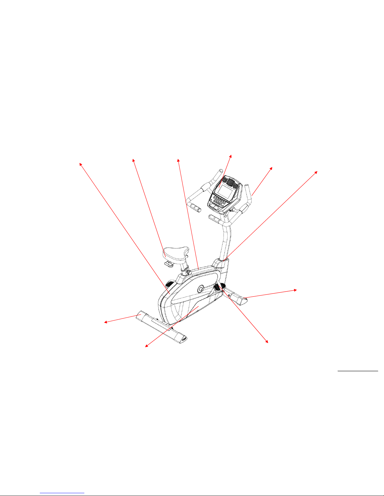
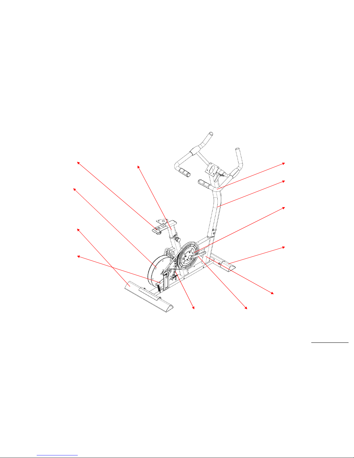
SU136 Outlines
SU136 Skeleton
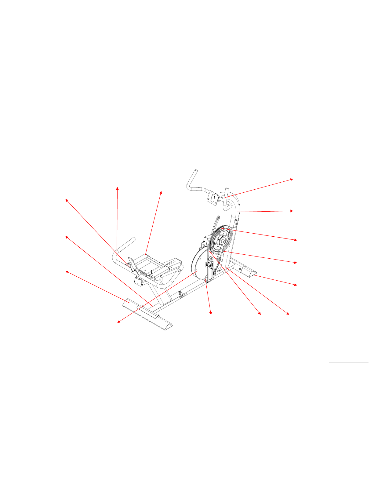
SR147 Outlines
SR147 Skeleton
2. Electronic Parts
SU136 Upper Controllers
SR147 Recumbent Controllers
SU136 Lower Controller and Driver
SR147 Lower Controller and Driver
3. Electrical Configurations
4. Product Operation
5. Unit Block Diagrams
6. Basic Connections and Wiring
7. Product Safety Instructions
8. Error Messages / Troubleshooting
9. SU136-YB02 Troubleshooting
9-1 Console
9-2 Handle Bar and Console Mast
9-3 Seat and Sliding Seat Mount
9-4 Crank Arm and Pedal
9-5 Left and Right Shrouds
9-6 Inner Slide Inner Slide
9-7 Twin Crank Arms, Belt, Idler Bracket and Drive Pulley
9-8 Flywheel
9-9 Console and Error Messages
9-10 Slipping Belt and Belt falling Off
9-11 Noises


 Service manual")


