Dycon D1551 User manual

D1551_D1553 installation manual 27042022 V2
Overview
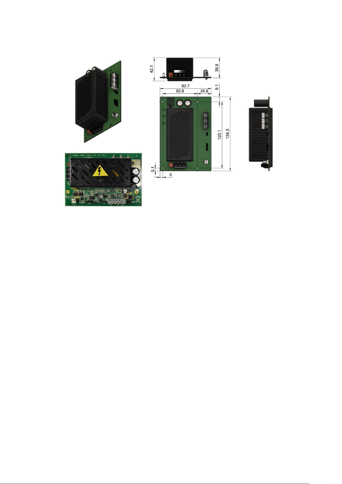
The Dycon D1551 and D1551 are 1A and 3A switched mode power supplies with an opto-relay output for
signalling the status of the unit with PCB-mounted, LED status indicators. Both units provide a nominal 12V
when powered from a 230V AC supply with battery backup.
The power supplies have the following features:
-ON/OFF power switching control input with pull-up, compatible with voltage-free contacts
-Jumper for selecting normally OPEN or normally CLOSED for switched output operation
-ON (OK) LED display indicating normal operation and ON/OFF switching status
-Battery LED indicating standby operation and ON/OFF output switched status
-Fault LED and separate fault opto-relay output for comprehensive fault monitoring
-Battery connection monitoring
-Battery deep discharge protection
-Inductive and capacitive load switching surge protection and snubbing
-Electronic overload protection with automatic reset
-Highly efficient power conversion –better than 84% at full load
-Low voltage drop when in standby mode
The ON/OFF switched output
The ON/OFF switched output is designed for highly inductive loads such as access control door
strikes and locks and is protected from high voltage back-EMF spikes.
Battery types
All standard VRLA (lead acid) batteries are supported. The standard battery connector for 2.1Ah &
7/8Ah batteries is a FASTON 4.75. For 17Ah & 24Ah batteries, please specify M5 connectors when
ordering
Connection layout for D1551
Version No:5
Material: PCB
Date: 25/03/2021
Projection:
General Tolerances:
+-0.5mm
Description: D1551
Scale
1:1.5mm
LED's
Mains Connection
Live
Earth
Neutral
BAT PROG INV
PSU FLT 0V
ON/OFF -/+ 12V
M3 x 6 mm panhead
recommended with 10
mm high
hex stand off

D1551_D1553 installation manual 27042022 V2
Dimensions for D1551
Connection layout for D1553

D1551_D1553 installation manual 27042022 V2
Dimensions for D1553
Installation
Mount the metal enclosure onto the wall.
Connect the Live, Earth and Neutral terminals to an un-switched fused spur.
Connect the On/Off switching control to the control unit. Select the mode of operation using the
jumper (see below).
Connect the Normally Closed relay output to the monitoring equipment used to report and signal
equipment faults.
Connect the 12V power output to the system.
Switch on the AC supply and confirm that the AC OK LED is lit.
External Power Supply (AC Supply)
The power supply has a three-way terminal block for Live, Earth and Neutral connections. When
supplied boxed, earth is connected to the metal enclosure and the lid earthed with a flying push-fit
lead.
12V Power Output
Terminal blocks are provided to connect to the system. The output is floating and can be referenced
to earth if required. The output is controlled by the ON/OFF input (see below). The output is
electronically short circuit and overload protected and suitable for switching highly inductive loads.
The short circuit protection is intelligent, and power will be restored when a short is removed when
still connected to the load, requiring no further user/installer intervention.
The output switch-on retry time is adaptive and will be extended to a maximum of 18 seconds after
a long duration short to prevent excessive switch power dissipation.

D1551_D1553 installation manual 27042022 V2
The PSU power rail is continuously monitored for over-voltage and in the event of a high voltage
condition, the output will be automatically switched off and a fault signal
LED Indications
The status of the PSU is displayed by three LEDs, see below for their meaning:
KEY:
●LED on
○LED off
☼LED blinking
STATE
OK LED
GREEN
BAT LED
YELLOW
FLT LED
RED
AC ON
●
○
○
AC OFF
○
●
●
Output Off, AC ON
☼
○
○
Output Off, AC Off
○
☼
●
Output Fault, AC ON
●
○
●
Output Fault, AC OFF
○
●
●
Battery Fault, AC ON
●
●
●
Low Battery Fault, AC OFF
○
●
●
Output Off, AC ON, Battery Fault
☼
☼
●
Output Off, AC ON, Output Fault Pending
☼
○
●
Output Off, AC OFF, Output Fault Pending
○
☼
●
Output Off, AC OFF, Low Battery Fault
○
☼
●
Output On, AC ON, Over Voltage Fault
●
○
●
Output Off, AC ON, Over Voltage Fault
☼
○
●
Output Off, AC Off, Low Battery Fault
○
☼
●
Output On, AC ON, Over Voltage Fault
●
○
●
Output Off, AC ON, Over Voltage Fault
☼
○
●

D1551_D1553 installation manual 27042022 V2
PSU Fault
-The normally closed (NC) fault opto-relay will open with the following fault conditions:
-Thermal shutdown due to overload
-Switch mode low-voltage output power fault
-Switch mode over-voltage output power fault
-12V output either shorted or overloaded
-Battery disconnected fault
-Low battery voltage fault
The relay contacts are voltage-free and floating. The PSU fault relay status will not be changed when
the output is switched on or off using the ON/OFF input.
ON/OFF Input
This input is 30V tolerant and 5V logic compatible. It has an internal 100K resistor pull-up connected to 5V
and is designed to work with 5V logic outputs, NO and NC voltage-free contacts and open collector outputs.
If the ON/OFF input is left unconnected when the jumper is not fitted, the power supply will be switched on.
Switching examples are shown below:
ON /
OFF
0V
ON /
OFF
0V
Open
Collector Normally closed
contacts
Jumper not fitted. PSU
output on when collector is
low (transistor on)
Jumper fitted. PSU
output on when contacts
are open
Battery Management
The battery is continuously monitored for connection and the charging output has reverse polarity
and safe-area current-limit protection. The battery has deep discharge cut-out protection when
operating in standby mode. The charging output uses constant current charging to reduce recharging
times.
Maintenance
There are no serviceable parts or fuses. No maintenance is required other than routine periodic
testing. Please note that high voltage is present under the cage –handle with care. Do NOT touch.
Do NOT remove the cage.

D1551_D1553 installation manual 27042022 V2
In case of problems, please telephone Dycon Technical Support on +44 (0)1443 471 90, or, email
Power supply
Type A, Ungraded, Environmental Class 2
Voltage input
195VAC –265VAC at 50 –60Hz
AC input current
D1551 –200mA, D1553 –400mA
AC input fuse
D1551 –1A, D1553 –2A
Output voltage with AC power
Maximum 13.9V, minimum 13.5V
Output ripple
Less than 0.25V peak to peak at full rated output
Maximum output current at full load
D1551 –1A, D1553 –3A
Battery charging current and voltage
300mA maximum at 13.7V float charge voltage
Minimum standby output voltage
9.6V
Maximum Power input at full load
D1551- 16W ; D1553 –47W
Fault Relay rating
60V at 100mA, 14ohms closed
Efficiency
85% @ 8A load
Maximum overvoltage cut-out
14.5V ±3%
Low battery fault
11V ±3%
Low-voltage power output fault
12.3V ±3%
Battery deep discharge voltage limit
10V ±3%
Automatic output reset time
10ms to 18s (Depending on nature and duration of the fault)
Operating temperate range
-10°C to +40°C
Humidity
95% non-condensing
1A version
D1551
3A version
D1553
Housing Type
Suitable batteries
Dimensions
H x W X D
(mm)
Weight
(Kg)
D1551-A
D1553-A
Steel, small-size A housing
1 x 7/8Ah
235 x 170 x 85
1.35
D1551-B
D1553-B
Steel, medium-size B housing
2 x 7/8Ah
260 x 320 x 90
2.15
D1551-XB
D1553-B
Steel. Clam-shell lid XB housing
2 x 7/8Ah or 2 x 17Ah
295 x 425 x 90
2.45
D1551-XLB
D1553-XLB
Steel, standard-size XLB housing
2 x 7/8Ah or 2 x 17Ah
295 x 425 x 90
2.45
D1551-XLBD
D1553-XLBD
Steel, extra-deep XLBD housing
Up to 4 x 17Ah
295 x 490 x 165
4.65
D1551-C
D1553-C
Steel, large C-size housing
2 x 7/8Ah or 2 x 17Ah
345 x 430 x 90
3.55
D1551-E
D1553-E
Steel, very-large E-size housing
2 x 7/8Ah or 2 x 17Ah
405 x 500 x 90
6.05
D1551-G
D1553-G
Steel, extra-large G-size housing
2 x 24Ah or up to 4 x 17Ah
690 x 455 x 165
8.75
D1551-W
D1553-W
Plastic IP65, W-size housing
1 x 2.1Ah or 1 x 7/8Ah
245 x 195 x 90
1.70
D1551-P
D1553-P
PCB-only version
Depends on housing
140 x 96 x 42
0.25
Dycon Accessories, suitable for use with both D1551 & D1553, which can be specified to be factory-fitted into the PSU housing
D15X8-500mA
8-way output splitter (8 x 500mA glass fuses)
49 x 108 x 17
0.70
D15X8-1A
8-way output splitter (8 x 1A glass fuses)
49 x 108 x 17
0.70
D15X4-BNP
4-way output splitter with 4 x BNC sockets & video loop-through
71 x 128 x 15
0.80
DFX4-0P
4-way output splitter with 4 x self-resetting PET fuses
40 x 60 x 19
0.20
DFR-1-12
12VDC universal output relay module
40 x 16 x 19
0.26
Specifications
This manual suits for next models
1
Table of contents
Other Dycon Power Supply manuals