Dyconn Butterfly DE500D-C User manual


Page
2
Dual Arm Articulating TV/Monitor Desk Clamp Mount (Butterfly Series)
Model: DE500D-C
Instruction Manual
Images may different from actual product
Disclaimer
It is Dyconn’s intention to have all the correct information represented within this manual.
Although we try our best, Dyconn makes no claim that the information comprised herein
covers all conditions or details in connection with installation or use of this product. Dyconn
assumes no responsibility for accuracy or adequacy of information comprised in this
document. The information comprised here is subject to change without notice or obligation
of any kind.
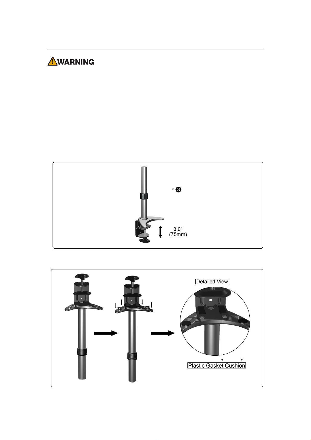
•A warning alerts you to the possibilities of personal injury or damage to equipment
if you do not follow the corresponding instructions. It is installer's responsibility to
make sure all components are properly assembled and installed using the
instructions manual provided.
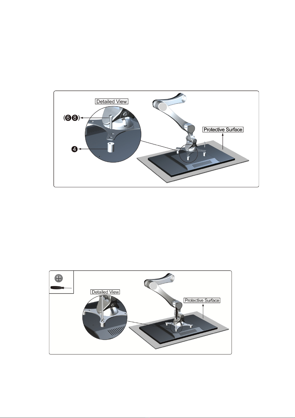
•Using improper screws or screw size may damage your display. If spacers are
required, be sure to use correct size of screws. Proper screws will easily and
completely thread into the display mounting holes. Inadequate thread
engagement in the display may cause display to fall.
•It is installer’s responsibility to make sure the combined weight of all components
does not exceed weight capacity. Exceeding weight capacities can result in
severe personal injury or damage to equipment. It is installer’s responsibility to
make sure the maximum combined weight of all components does not exceed
weight capacity of 18Kg (39.6lbs)
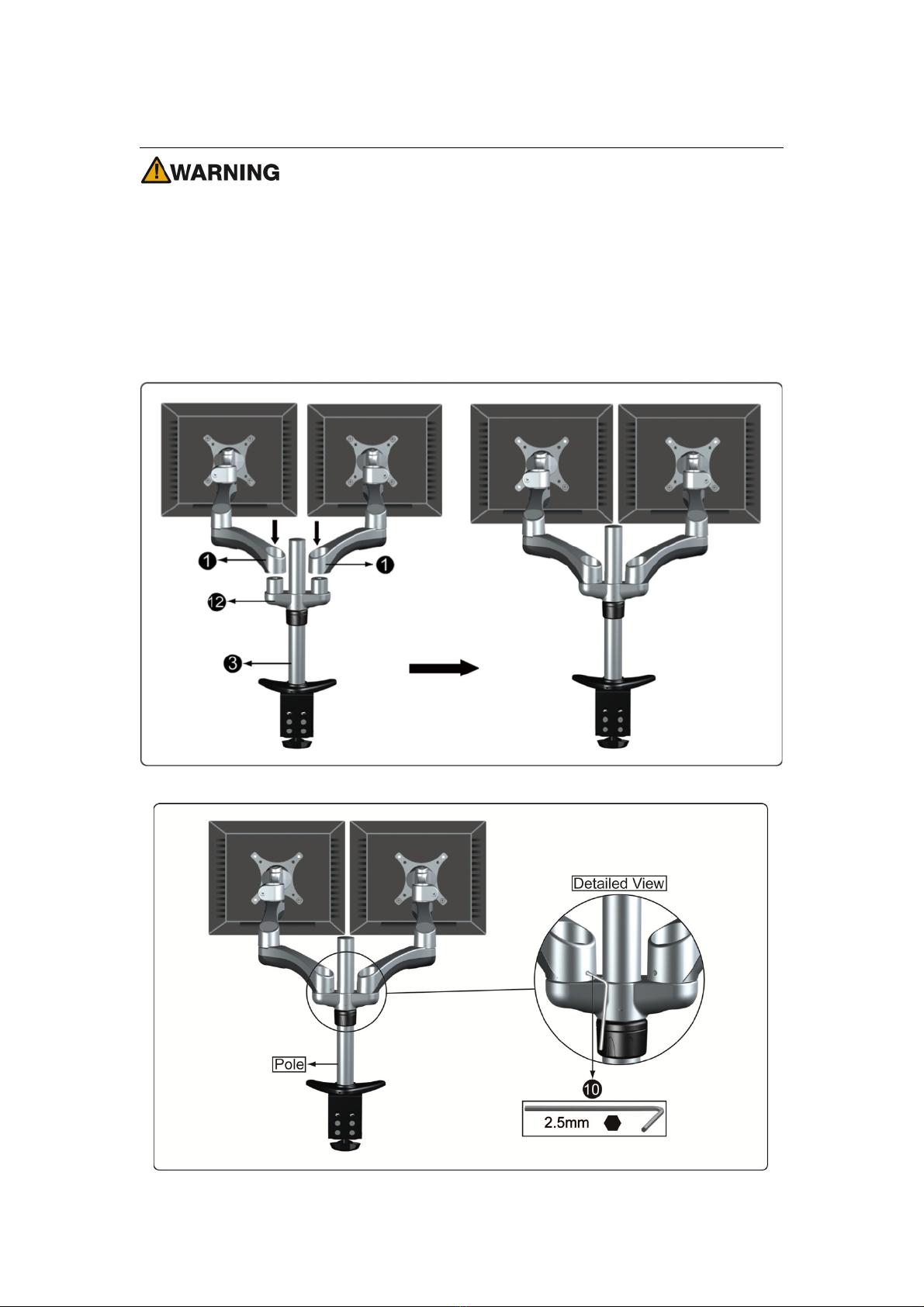
•Allowing any part of your component cables to be caught between movable parts
can result in serious personal injury or damage to equipment.
Read the following warning before installing
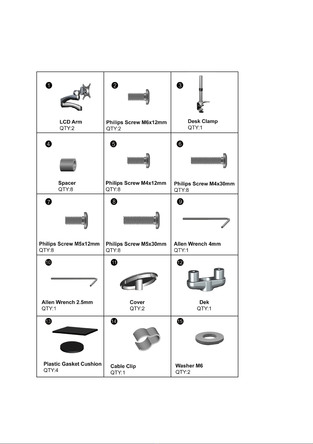
!Verify all parts are included. Do not install if the products or hardware is damage. Not
all hardware included will be used.
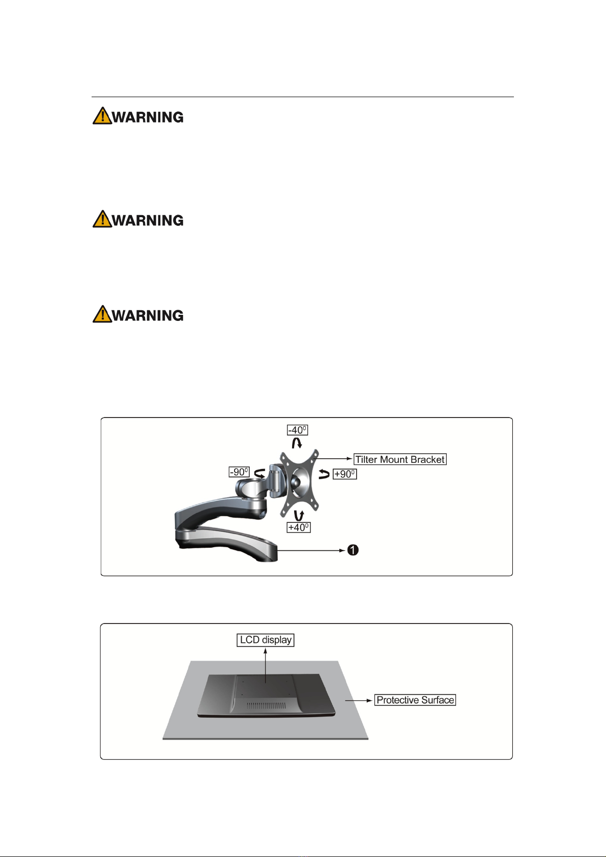
!This product contain moving parts, Use with caution
!Determine approximate location for mounting and keeping in mind the display size,
extension, height adjustment and pitch / roll requirements.
!This product contains small item, keep these items away from children
!Do not exceed the maximum weight capacity for this product. Exceeding the weight
capacity can result in serious personal injury or damage to equipment!

Page
3
Specifications
Combined Weight Capacity
39.6(LBS) / 18(KG)
Suits LCD Flat Panel Displays
12”(300mm)-24”(610mm)
Maximum Extension
18”(457mm)
Depth from Pole (Closed)
2.3”(57.5mm)
Tilt adjustment
+/- 40 degree
Display Pan Swing- Side to side
+/- 90 degree
Pivot (Desk / Display / Arm)
360 / 180 /360 degree
Maximum Mounting Surface Thickness
3”(75mm)
VESA Compatibility
75x75mm and 100x100mm

Page
4
Supplied Parts

Page
5
Required Tools
ASSEMBLY and INSTALLATION
INSPECT THE MOUNT BEFORE ASSEMBLY
1. Carefully inspect/verify that all components are present.
2. If the mount/components are damaged or missing, please contact the company/seller
of the product you purchased and report the issue.
Note: Read all assembly instructions before staring the installation process.

Page
6
Figure 1-1
Figure 1-2
Step 【1】Installation of Desk Clamp
Using improper screws or screw size may damage your display. Screw should be first
inserted and turned by hand before using the Hexagon key or with Screwdriver to
complete the attachment.
Note: Other tools may be required depending on your method of installation.
Note: It is installer’s responsibility to make sure the desktop structure to which this
product is attached can support the combined weight of all components Maximum
combined weight 18Kg (39.6lbs)
Installation of Desk Clamp to Desk
1. Adjust the height of Desk Clamp (3) to suit desktop surface. (See Figure 1-1)
2. Place the Plastic Gasket Cushion as shown. (See Figure 1-2)

Page
7
Figure 1-3
Figure 1-5
Figure 1-6
3. Place the Desk Clamp (3) on top of the desk in the desired position and ensure the
clamp opening is facing towards the edge of desktop.(See Figure 1-3) Turn and
tighten by hand to ensure that the Desk Clamp fully contacts to desktop surface and it
is secure in place. (See Figure 1-4)
4. You will need to loosen the Collar supplied. Position Collar at desired height and
orientation. Tighten by hand so the Collar assembly is firmly in place. (See Figure
1-5)
5. Place the DEK by inserting it down from the top to the pole, proceed to tread with
2.5mm Allen Wrench 2.5mm (10) supplied. (See Figure 1-6)
Figure 1-4

Page
8
Figure 2-1
Figure 2-2
Step 【2】Display Installation
Using improper screws or screw size may damage your display. If spacers are required,
be sure to use correct size of screws. Proper screws will easily and completely thread into
the display mounting holes. Inadequate thread engagement in the display may cause
display to fall.
It is installer’s responsibility to make sure the combined weight of all components does not
exceed weight capacity. Exceeding weight capacities can result in severe personal injury
or damage to equipment. It is installer’s responsibility to make sure the combined weight
of all components does not exceed weight capacity of 18Kg (39.6lbs)
Desk Mount LCD Arm will only work when a display is properly installed.
Attaching the Display
1. Ensure Tilter Mount Bracket of LCD Arm Assembly is able to swivel and tilt easily.
(See Figure 2-1) Adjust as required before proceeding to next step.
2. Carefully place the display face down on protective surface.(See Figure 2-2)

Page
9
Figure 2-3
Figure 2-4
3. Determine depth of recessed mounting holes relative to back of surface of display.
4. Select proper length of Screws (6、8) place the Spacers (4) on the back of display,
follow by position and orient the mounting holes in the Tilter Mount Bracket so that the
mounting holes on the Tilter Mount Bracket and Spacers (4) are aligned. (See Figure
2-3)
5. Using Philip Screwdriver, install selected Screws (6、8) through mounting holes on
Tilter Mount Bracket and Spacers (4), finally into the display monitor. Tighten Screws
with Philip Screwdriver so the Tilter Mount Bracket is firmly attached to the display
monitor. Do not over tighten the Screws. Stop immediately if you encounter any
resistance. (See Figure 2-4)
Note: All Spacers or Screws used should be the same length.

Page
10
Figure 3-2
Step 【3】Attaching LCD Arm Assembly
Desk Mount LCD Arm Assembly will only work when a display is properly installed.
Attaching the LCD Arm Assembly
1. Attach the LCD Arm Assembly (1) to the Pole by inserting the LCD Arm Assembly
down from top into the pole. (See Figure 3-1)
2. Once you have LCD Arm Assembly is in desired position, tighten with Hex Grub
Screw using Hex Allen Wrench 2.5mm (10) provided so the assembly is firmly in place.
(See Figure 3-2)
Figure 3-1

Page
11
Figure 3-3
3. Place the Cover (11) and tighten with Phillips Screw M6x12mm (2) and Plastic
Washer (15) using Phillip Screwdriver. Do not over tighten. This is to prevent the LCD
Arm Assembly to be lift unnecessary. (See Figure 3-3)

Page
12
Figure 4-1
Step 【4】Cable Management
Ensure LCD Arm Assembly is fully extended before connecting cables.
Exercise caution when attaching or removing the display to avoid personal injury or
damage to equipment. Disconnect power before removing the display.
Note: Ensure leave enough slack in the cables to allow for movement of the Arms.
Installing Cable Management
1. Connect cables to display monitor. Position the display at its highest position to ensure
that there is sufficient cabling at the end of the Arms so that the cables are not stretched
or pulled out when the display is moved. (See Figure 4-1)
2. Feed the cables by pushing the cables into cable bracket entry slot on the underside of
the Arms as shown. (See Figure 4-2)
Figure 4-2

Page
13
Figure 4-3
3. Use the supplied Cable Clip (14)to secure display cable to the pole.(See Figure 4-3)

Page
14
Figure 5-2
Figure 5-1
Step 【5】Adjusting the Display Monitor
Forced movement of the LCD Arm Assembly or Mount Bracket without loosening the
screws will damage LCD Arm Assembly or display monitor.
Exercise caution when adjusting the display, to support the display to avoid damage to
equipment. Disconnect power before removing the display.
Adjusting the LCD Arm Assembly Resistance
1. Product is brilliantly engineered to control the resistance in the Tilter Mount Bracket to
suit your display swing side to side of 90 degree and tilt forward and backward of 40
degree. It is possible to control the amount of resistance in the Tilter Mount Bracket to
suit your display monitor.
2. To support display monitor when adjusting resistance of the Desk Mount LCD Arm
Assembly. (See Figure 5-1)
3. Referring to the weight of the display monitor. If the Tilter Mount Bracket tends to
automatically fall, it may be required to adjust the Tilter Mount Bracket joint to suit your
display monitor tilt position of forward and backward of 40 degree. This can be done
by using Hex Allen Wrench 4mm (9) supplied, to increase the resistant of the Tilter
Mount Bracket in order to secure tilt position, adjust the M5x15mm Tension Hex
Socket Cap Screw located around the Tilter Mount Bracket Joint using the supplied
4mm Hex Allen Wrench. (See Figure 5-2)

Page
15
4. To increase or decrease the resistance of the Pivot Joint to suit display monitor swing
side to side, adjust the Tension Hex Cap Screw located on front side of the LCD Arm
to secure the position. (See Figure 5-3)
5. To increase the resistance, tighten the M5x15mm Tension Hex Socket Cap Screw
using Allen Wrench 4mm (9) supplied in a clockwise direction. To decrease the
resistance, loosen the M5x15mm Tension Hex Socket Cap Screw using Allen Wrench
4mm (9) supplied in an anti-clockwise direction.
6. This product is brilliantly engineered and is designed to adjust quickly and easily
according to your needs. To adjust the height, remove the Extension Arm from the
Pole. Loosen Collar, raise or lower the Collar on Pole, attaching the LCD Arm to
achieve your desired position. (See Figure 5-4) If this product tends to automatically
move to side, it may be required tension adjustment on the LCD Arm to suit your
display monitor arm swing to side position. This can be done by using Hex Allen
Wrench 2.5mm (10) supplied. (See Figure 5-5)
Figure 5-3
Figure 5-4

Page
16
Figure 5-5

Page
17
Step 【6】Ergonomic Guidelines
Note: Proper ergonomic design is necessary to prevent repetitive strain injuries, which
can develop over time and can lead to long-term disability
1. Ensure the correct focal distance for ultimate visual comfort. For visual comfort, a viewing
distance between 460mm (18”) to 610mm (24”) is recommended. (See Figure6-1)
Figure 6-1

Page
18
2. To assess the fit between a person and their work, agronomists recommended that the
optimal of your screen position should be slightly below eye level. Viewing angle should
be approximately 10°-20° downward of the screen’s center. The lumbar (bottom five
vertebrate in the spine) needs to be supported to decrease disc pressure. Providing both
a seat back that inclines backwards and has a lumbar support is critical to prevent
excessive low back pressures. The combination which minimizes pressure are
recommended on seating ergonomic which the wrist angle must be straight, seat angle
and knee angle must be on 90° angle. Angular adjustment to reduce reflection on your
monitor. The range should be between 5° forward tilt to 15° backward tilt. (See Figure6-2)
Figure 6-2

Page
19
DYCONN PRODUCT WARRANTY
To obtain warranty service, contact Dyconn customer service at (855) 239-2666 or visit
www.dyconn.com. Dyconn disclaims any liability for modification, improper installations,
or installations over specified weight range. Dyconn will not be liable for any damages
arising out of the use or inability to use Dyconn products. Warranty specification is subject
to change without prior notice.
Table of contents
Other Dyconn TV Mount manuals