dymax UVCS 2.0 User manual

UVCS Version 2.0 and UVCS 39 User Guide
For Use with Fusion Flood Lamps
◼Instructions for Safe Use
◼Setup and Operation
◼Maintenance
◼Ordering Spare Parts and Accessories

2
Dymax UVCS 2.0 Light-Curing Conveyor User Guide
About Dymax
UV/Visible light-curable adhesives. Systems for light curing, fluid dispensing, and fluid packaging.
Dymax manufactures industrial adhesives, light-curable adhesives, epoxy resins, cyanoacrylates, and activator-cured adhesives.
We also manufacture a complete line of manual fluid dispensing systems, automatic fluid dispensing systems, and light-curing systems.
Light-curing systems include LED light sources, spot, flood, and conveyor systems designed for compatibility and high performance
with Dymax adhesives.
Dymax adhesives and light-curing systems optimize the speed of automated assembly, allow for 100% in-line inspection, and increase
throughput. System designs enable stand-alone configuration or integration into your existing assembly line.
Please note that most dispensing and curing system applications are unique. Dymax does not warrant the fitness of the product for the
intended application. Any warranty applicable to the product, its application, and use is strictly limited to that contained in the Dymax
standard Conditions of Sale. Dymax recommends that any intended application be evaluated and tested by the user to ensure that desired
performance criteria are satisfied. Dymax is willing to assist users in their performance testing and evaluation by offering equipment trial
rental and leasing programs to assist in such testing and evaluations. Data sheets are available for valve controllers or pressure pots upon
request.

3
Dymax UVCS 2.0 Light-Curing Conveyor User Guide
Contents
Introduction....................................................................................................................................................4
Introduction to the User Guide ....................................................................................................................................... 4
Where to Get Help .......................................................................................................................................................... 4
Safety..............................................................................................................................................................4
General Safety Considerations ........................................................................................................................................ 4
Specific Safety Considerations......................................................................................................................................... 5
Dymax UV Light-Curing System Safety Considerations ................................................................................................... 5
Product Overview ...........................................................................................................................................7
Description of the Dymax UVCS Conveyor System.......................................................................................................... 7
Unpacking and Setup ......................................................................................................................................7
Unpacking and Inspecting Your Shipment....................................................................................................................... 7
Parts Included in the UVCS Conveyor.............................................................................................................................. 8
Lamp Installation and System Interconnect ....................................................................................................8
Fusion Series Lamps ........................................................................................................................................................ 8
Conveyor Operation...................................................................................................................................... 12
Setting Adjustments .....................................................................................................................................13
Adjusting Conveyor Blower Speed ................................................................................................................................ 13
Maintenance.................................................................................................................................................14
Belt-Tracking Adjustment.............................................................................................................................................. 14
Conveyor Belt Replacement.......................................................................................................................................... 14
Troubleshooting............................................................................................................................................ 17
Spare Parts and Accessories.......................................................................................................................... 17
Conveyor Accessories.................................................................................................................................................... 17
Fusion Lamp Spare/Replacement Parts......................................................................................................................... 18
UVCS Conveyor Spare/ Replacement Parts ................................................................................................................... 18
Specifications................................................................................................................................................ 19
Definition of Terms.......................................................................................................................................21
Warranty ...................................................................................................................................................... 22
Index.............................................................................................................................................................23

4
Dymax UVCS 2.0 Light-Curing Conveyor User Guide
Introduction
Introduction to the User Guide
This guide describes how to assemble, use, and maintain the Dymax UVCS Light-Curing Conveyor System safely
and efficiently.
Intended Audience
Dymax prepared this user guide for experienced process engineers, technicians, and manufacturing personnel.
If you are new to UV light curing and do not understand the instructions, contact Dymax Application
Engineering to answer your questions before using the equipment.
Where to Get Help
Dymax Customer Support and Application Engineering teams are available in the United States, Monday
through Friday, from 8:00 a.m. to 5:30 p.m. Eastern Standard Time. You can also email Dymax at
[email protected]. Contact information for additional Dymax locations can be found on the back cover of this
user guide.
Additional resources are available to ensure a trouble-free experience with our products:
◼Detailed product information on www.dymax.com
◼Dymax adhesive Product Data Sheets (PDS) on our website
◼Material Safety Data Sheets (SDS) provided with shipments of Dymax adhesives
Safety
WARNING! If you use a Dymax light-curing conveyor without first reading and understanding
the information in this user guide, injury can result from exposure to high-intensity light. To
reduce the risk of injury, read and ensure you understand the information in this user guide before
assembling and operating a Dymax conveyor system.
To use this system safely, it must be set up and operated in accordance with the instructions given
by Dymax. Using the system in any other manner will impair the protection of the system. Dymax
assumes no liability for any changes that may impair the protection of the system.
General Safety Considerations
All users of Dymax equipment should read and understand this user guide before assembling and using the
equipment.
To learn about the safe handling and use of light-curable formulations, obtain and read the SDS for each
product. Dymax includes an SDS with each adhesive sold. In addition, fluid product SDS can be requested
through our website.

5
Dymax UVCS 2.0 Light-Curing Conveyor User Guide
Specific Safety Considerations
Dymax light-curing conveyors are designed to maximize operator safety and minimize exposure to UV light. To
use the conveyor safely, it must be set up and operated in accordance with the instructions in this user guide.
Dymax UV Light-Curing System Safety Considerations
Dymax UV light-curing technology has been used successfully for over 30 years. The fast cure, one-component
nature of our UV light-curing technology has made it the process of choice for many manufacturers requiring a
"cure on demand" assembly process. Operators must understand these four concepts to use the UV light
source safely: UV exposure, high-temperature surfaces, ozone, and bright, visible light. Each is described
below.
UV Exposure
Standard Dymax UV light-curing systems have been designed primarily to emit UVA energy (Figure 1). UVA
energy is generally considered the safest of the three UV ranges: UVA, UVB, and UVC. Although OSHA does not
currently regulate UV light exposure in the workplace, the American Conference of Governmental Industrial
Hygienists (ACGIH) does recommend Threshold Limit Values (TLVs) for ultraviolet light.
The strictest interpretation of the TLV (over the UVA range) for workers’ eyes and skin allows continuous
exposure up to 1 mW/cm2(intensity). Unless you are placing bare hands into the curing area, it is unusual to
exceed these limits. To put 1 mW/cm2limit into perspective, a cloudless summer day will typically exceed
3 mW/cm2of UVA light, and also include the more dangerous UVB light (primarily responsible for sun tans,
sun burns, and skin cancer) as well.
Figure 1. UV Spectrum
Checking the Workstation
The human eye cannot detect "pure" UV light, only visible light. A radiometer should be used to measure stray
UV light to confirm the safety of a UV light-curing process. A workstation that exposes an operator to more
than 1 mW/cm2of UVA continuously should be redesigned.
Protecting Operators
Light-curing technology can be a regulatory compliant, "worker-friendly" manufacturing process when the
proper safety equipment and operator training is utilized. There are two ways to protect operators from UV
exposure: shield the operator and/or shield the source.

6
Dymax UVCS 2.0 Light-Curing Conveyor User Guide
Shield the Operator
UV-Blocking Eye Protection - UV-blocking eye protection is recommended when operating UV light-curing
systems. Both clear and tinted UV-blocking eye protection is available from Dymax.
UV-Blocking Skin Protection —Where the potential exists for UV exposure upon skin, opaque, UV-blocking
clothing, gloves, and full-face shields are recommended.
Shield the Source of UV
Any substrate that blocks UV light can be used as a shield to protect workers from stray UV light. The following
materials can be used to create simple shielding structures or blind corners:
Sheet Metal —Sheet metal (aluminum, steel, stainless steel, etc) should be coated black or black anodized to
minimize reflection of UV and visible light toward operators.
Rigid Plastic Film —Transparent or translucent/UV-blocking plastics (typically polycarbonate or acrylic) are
commonly used to create shielding where some level of transparency is also desired. These rigid plastic films
are available either water clear or tinted.
Flexible Film —UV-blocking, flexible urethane films can be used to quickly create workstation shielding. This
UV-blocking, flexible urethane film is available from Dymax. Call for assistance.
High-Temperature Surfaces
Surfaces exposed to high-intensity curing lights may rise in temperature. The intensity, distance, exposure
time, cooling fans, and composition of the surface can all affect the rise in surface temperature. In some cases,
exposed surfaces can reach temperatures capable of producing a burn or causing damage to a substrate. In
these cases, care must be taken to ensure either a more moderate surface temperature or appropriate
protection/training for operators.
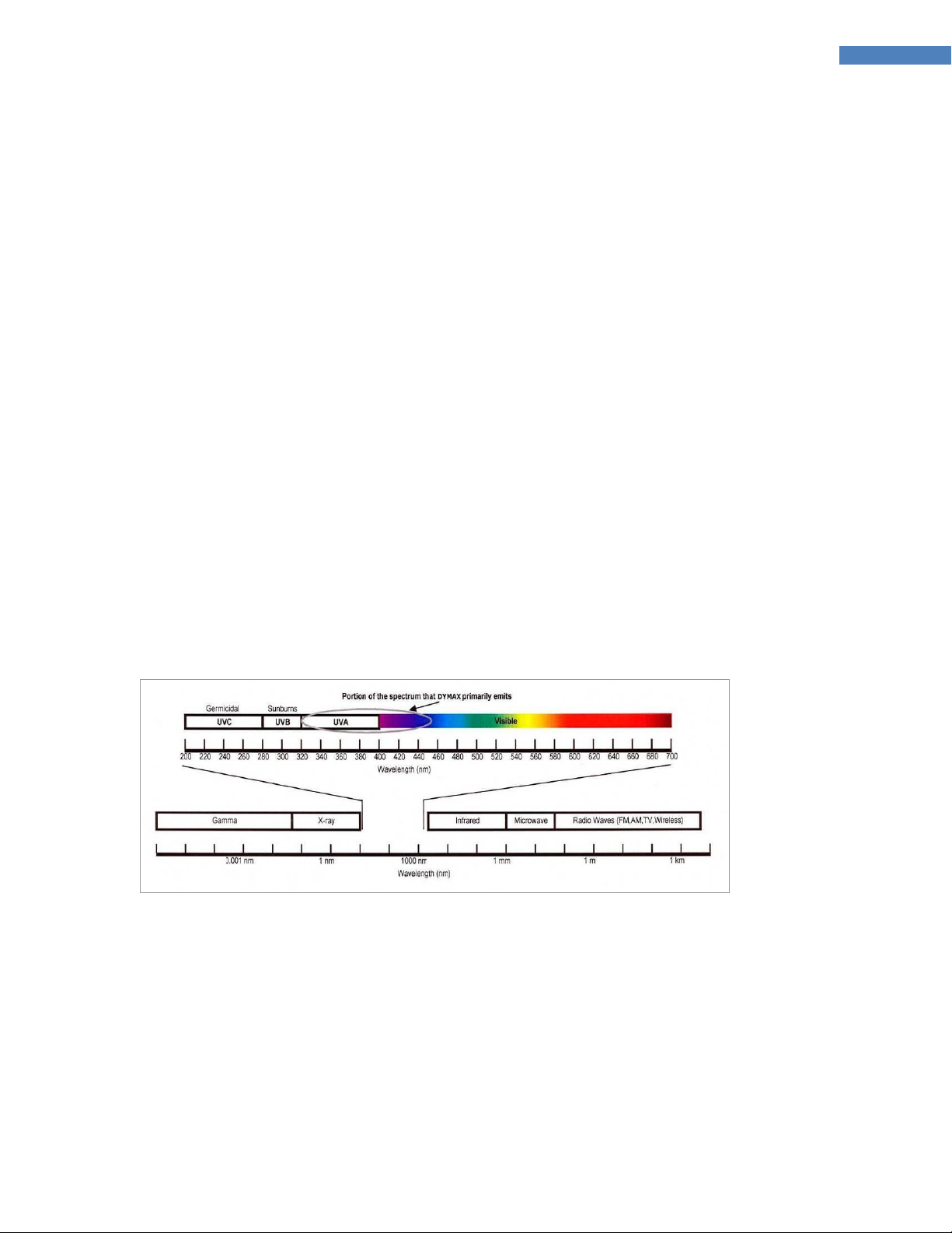
Ozone
Standard Dymax lamps (UVA type) generate an insignificant amount of UVC and therefore essentially no
ozone. Some UV light-curing systems, like those used to cure UV inks, emit primarily “shortwave” (UVB and
UVC) energy. Upon exposure to UVC light (specifically <240 nm), oxygen molecules (O2) split into oxygen
atoms (O) and recombine with O2to create ozone O3. The current, long-term ozone concentration limit
recommended by ACGIH, NIOSH, and OSHA is 0.1 ppm (0.2 mg/m3).
Bright, Visible Light
The bright, visible light energy emitted by UV light-curing systems can cause eye strain if proper eye protection
or shielding is not used. The proper use of tinted eye protection and/or opaque/tinted shielding can be utilized
to reduce eye strain and address this concern.
Summary
UV light sources can be more “worker friendly” than many commonly accepted industrial processes, provided
the potential concerns are addressed. Contact your Dymax representative for information regarding the
proper use of Dymax UV light-curing systems.

7
Dymax UVCS 2.0 Light-Curing Conveyor User Guide
Product Overview
Description of the Dymax UVCS Conveyor System
The Dymax UVCS Light-Curing Conveyor System is designed to provide reliable and consistent processing of
UV/Visible light-curable adhesives and coatings. Standard features include a Direct-Drive Motor, adjustable
Lamp height, integrated and adjustable Cooling System, and a UV-Resistant Belt.
The UVCS is designed for bench- or table-top operations. The self-contained Cooling System and integral UV
light allows the Conveyor to be placed virtually anywhere space permits.
Dymax UV light-curing sources are capable of curing a wide variety of light-curable adhesives, coatings, and
inks. They have extensive use in a variety of applications such as bonding, potting, sealing, and encapsulating.
These light sources offer exceptional versatility and expandability to accommodate most process demands.
A large number of accessories are available for the base Conveyor. These items address safety, as well as
functional flexibility, which is depicted and discussed in this manual.
Figure 2. UVCS Conveyor System with Two Fusion Lamps (UVCS 39 not shown)
Unpacking and Setup
Unpacking and Inspecting Your Shipment
When your conveyor arrives, inspect any boxes for damage and notify the shipper immediately of box
damage.
Open each box and check for equipment damage. If parts are damaged, notify the shipper and submit a claim
for the damaged parts. Contact Dymax so that new parts can be shipped to you immediately.

8
Dymax UVCS 2.0 Light-Curing Conveyor User Guide
Check that the parts included in your order match those listed below. If parts are missing, contact your local
Dymax representative or Dymax Customer Support to resolve the problem.
Parts Included in the UVCS Conveyor
◼UVCS Conveyor Unit
◼Lamp and Power Source Options (Dependent on model number ordered) - A Lamp Power Supply that
allows external electrical inputs and provides power to the Lamp located in the Reflector Assembly
Housing. The Power Supply contains the On/Off Power Switch, Control, and Interlock Circuitry.
The Power Supply also houses its own Cooling Fans. The rear panel has an AC Power Receptacle,
connections for the Lamp, Conveyor Interlocks, and Slave-Unit Control.
The Lamp Power Supply allows adjustment for different voltage and frequency conditions suitable for
virtually any electrical system in the world. Switching between 50 and 60 HZ frequency operation
requires movement of Capacitor Jumpers in the Power Supplies. See the Fusion Lamp Operators
Manual included with your Conveyor System for specific instructions.
◼Power Cord
◼Fusion “D” Bulb (PN 36399) is standard. “H” Bulbs (PN 36441) and “V” Bulbs (PN 38146) are available
upon request
◼UV Goggles, Two Pairs
◼Dymax UVCS Conveyor System User Guide
Lamp Installation and System
Interconnect
Fusion Series Lamps
NOTE: Refer to the Fusion Lamp operator's manual for detailed Irradiator and Power Supply information.
1. If the optional Conveyor Cart (PN 39215) or Plate Kit (42566) has been purchased, assemble the
Conveyor Cart prior to building the Conveyor System.
2. Uncrate and assemble the Conveyor. See Dymax UVCS-Fusion Conveyor System Quick Start
Instructions for Conveyor assembly instructions.
3. Install the Connector Cables from the Fusion Power Supply’s J-105B and J-106 Connectors to the rear
of the Conveyor (Figure 3).
4. Unpack the Fusion Lamp Assembly(ies). Each Lamp Assembly includes an Irradiator (Lamp), and
Lamp-Connector Cord (Figure 4). For Dual-Fusion Lamp units, the Master Lamp Assembly includes an
RF Detector, an RF-Detector Connector Cord, and “Master” to “Slave” Power-Supply Connector
Cords.

9
Dymax UVCS 2.0 Light-Curing Conveyor User Guide
CAUTION! Each Fusion Lamp Assembly has a fine mesh RF Screen covering the Lamp Face. Great
care should be taken during installation and handling of these units to avoid puncturing or damaging
the RF Screen. RF energy can be released if the RF Screen is damaged in any way.
Figure 3. Cable Configuration
Figure 4. Irradiator
5. Inspect the RF Screen on the bottom of the Irradiator. Make sure there are no rips or tears in the RF
Screen.
NOTE: Any tears in the RF Screen will result in an RF Interlock failure when the equipment is operated.
6. Mount the Irradiator(s) into the Conveyor’s Lamp Support (Figure 5). Take particular care not to
damage the Protective Screen covering the Bulb end of the Irradiators.
Figure 5. Conveyor with Lamp(s) Installed
7. Locate the RF Detector Mounting Bracket on the opening provided in the Lamp Basket Assembly
(Figure 7). The RF Detector senses microwave leakage through the Rubber Window in the wall of the
Conveyor. Microwave leakage indicates a torn Protective Screen on the bottom of the Irradiator.
NOTE: The RF Detector Assembly is pre-installed on all new conveyors purchased with Fusion Lamps.
8. Install the RF Detector next to the Fusion Irradiators on the Conveyor’s intake side (if not already
installed). Attach the RF Detector’s Connector Cord to the RF Detector (Figure 7).

10
Dymax UVCS 2.0 Light-Curing Conveyor User Guide
Figure 6. RF Detector Assembly
Figure 7. RF Detector Connector Cord
9. Connect the Irradiator Cable(s) to the Irradiators (Figure 8).
Figure 8. Irradiator Cable Connections
10. Unpack the Power Supply(ies). A 220-Volt Power Cord is provided with each Power Supply (Figure 9).
The Power Supplies may be configured for either 50 or 60 HZ operation and for 208-, 220-, 230-, or
240-Volt operation. Changing between 50 and 60 HZ operation requires repositioning of two
Capacitor Jumpers in each Power Supply. The Power Supply’s shipping box is labeled with the voltage
and frequency set at the factory. Detailed Power Supply setup instructions are provided in the Fusion
Lamp operator's manual.
Figure 9. Power Supplies (front)

11
Dymax UVCS 2.0 Light-Curing Conveyor User Guide
11. Position the Power Supply(ies) on the Conveyor’s Mounting Stand or in a location near the Conveyor.
Attach the Connector Cable leading from the RF Detector to the J-105A Receptacle on the back of the
Master Power Supply. Attach the cables leading from the back of the Conveyor to the J-105B and J-
106 Receptacles of the Master Power Supply (Figure 10). These cables are labeled to aid in assembly.
Figure 10. Power Supplies (back)
12. For dual-Fusion units, connect the Jumper Cable between J-107 of the Master Power Supply and J-
106 of the Slave Power Supply. Install the Jumper Plug in J-105A of the Slave Power Supply.
13. Connect the other end of the Irradiator Cable to the J-103 and J-104 Receptacles of the Power
Supply(ies). Connect the Power Cord to the back of the Power Supply and to a 208-240-Volt Power
Source.
14. Plug in the Conveyor and turn it on. When the Conveyor is operating, and the Belt is in motion, turn
the Power Supply on by closing the Breakers on both of the Power Supply’s Front Panels.
15. Turn the Irradiators on by pressing the Lamp On Button of the Master Power Supply (Figure 11). Both
the Master and the Slave Power Supplies will go through a warm-up cycle. The Blower inside the
Irradiators will turn on and the Lamps will ignite. The Lamps reach full intensity within 5 seconds
after ignition. Your UVCS Conveyor is now ready for operation.
Figure 11. Power Supply (front)

12
Dymax UVCS 2.0 Light-Curing Conveyor User Guide
Conveyor Operation
1. Install all safety accessories to protect operator from UV-light emissions.
2. Apply power to the Conveyor and turn it on.
3. Unlock the Speed Control Knob (Figure 13) and adjust the speed for the desired setting. The Speed
Control Knob is a 10-Turn Potentiometer and allows speed adjustment from approximately 0.9 FPM
to 32 FPM (feet per minute).
Figure 12. Conveyor Front Panel
Figure 13. Speed Control Knob
4. If any adjustments are needed for the Belt alignment, refer to the Maintenance Section of this
manual.
5. Adjust the height of the Lamps to the desired distance.
6. Once all the settings (speed and Lamp height) have been properly set, the Conveyor is ready for
operation.
7. When the Conveyor is operating and the Belt is in motion, turn the Power Supply on by closing the
Breaker(s) on both of the Power Supply’s Front Panels.
8. Turn the Irradiators on by pressing the Lamp On Button of the Master Power Supply (Figure 11). Both
the Master and the Slave Power Supplies will go through a warm-up cycle. The Blower inside the
Irradiators will turn on and the Lamps will ignite. The Lamps reach full intensity within 5 seconds
after ignition. Your UVCS Conveyor is now ready for operation.
NOTE: The Fusion Power Supplies are interlocked with the Conveyor so that the Conveyor must be
operating and the Conveyor Belt in motion before the Lamps will ignite. This prevents Belt overheating
and damage that can result if the Belt is stationary when the Lamp is turned on.

13
Dymax UVCS 2.0 Light-Curing Conveyor User Guide
Setting Adjustments
Adjusting Conveyor Blower Speed
The Blower controls the amount of cooling air provided to the Lamp Assemblies to keep them at proper
operating temperatures. A small percentage of the cooling air is also diverted downward through the
Conveyor Belt. This air flow provides a small hold-down force to keep light objects from moving while traveling
on the belt. The Exhaust Blower speed is set at the factory during final system testing for the Conveyor model
ordered.
If adjustment is required, remove the Access Panel from the front of the Exhaust Blower Housing (Figure 14),
unlock the Speed Control Knob (Figure 15), adjust the Exhaust Blower speed setting, and relock the Speed
Control Knob. The range of the Exhaust Blower Speed Control Knob is 0.0 to 0.85 turns. Table 1 shows the
approximate settings for Exhaust Blower speed.
Figure 14. Access Panel
Figure 15. Speed Control Knob
Table 1. Blower-Speed Potentiometer and Lamp-Cradle Height Settings for Optimum Bulb
Cooling
Model Number
Blower-Speed Potentiometer Setting
Height
1 in
3 in
4.5 in
UVCS-F-1-230
0.20
0.40
0.54
UVCS-F-2-230 or UVCS 39
0.45
0.54
0.80

14
Dymax UVCS 2.0 Light-Curing Conveyor User Guide
Maintenance
Belt-Tracking Adjustment
All Dymax UVCS Conveyors are factory adjusted to
provide proper tracking of the Belt. Should further
adjustments become necessary, there are two
knurled Adjustment Knobs located at the input end of
the Conveyor (Figure 16). To adjust tracking, simply
tighten the side to which the Belt is tracking.
NOTE: Do not over tighten the Belt. This will lead to
accelerated degradation of the Belt. The Belt should
be stoppable with moderate hand pressure.
Figure 16. Belt-Tension Adjustment Knob
Conveyor Belt Replacement
1. Remove the Pinch Guard from the motor side of the Conveyor by removing the two M4x8 Screws
(Figure 17) on the front side of the Conveyor and the M4x25 Screw (Figure 18) from the motor-drive
side of the Conveyor.
2. Remove the Pinch Guard from the input side of the Conveyor by removing the three M4x8 Screws
(Figure 19) from both sides.
Figure 17. Two M4x8 Screws
Figure 18. M4x25 Screw
Figure 19. Three M4x8
Screws
3. Remove all tension from the Belt by fully backing off the Belt-Tension Adjustment Knobs (Figure 16).
4. Position the Belt Splice to the end of the Conveyor (Figure 20). Remove the Fiberglass Rod that ties
the ends of the Belt together (Figure 21). Remove the Belt.
5. Run the new Belt around the Conveyor Frame (Figure 22).
6. Install the Fiberglass Rod through the Belt Loops.

15
Dymax UVCS 2.0 Light-Curing Conveyor User Guide
7. Apply some adhesive to both ends of the Fiberglass Rod to prevent it from moving during Conveyor
operation (Figure 23).
Figure 20. Spliced End of Belt
Figure 21. Fiberglass Rod
Figure 22. Replacing Belt
Figure 23. Applying Adhesive
8. Equally tighten the Belt-Tension Knobs (Figure 16) on both sides of the conveyor to remove excess
slack from the Belt. Enough tension should be applied on the Belt so that the Belt can only be moved
across the two Rollers by moderate hand pressure when the Conveyor is not running.
CAUTION! Excessive tightening of the Belt will result in early Belt failure. Since the two Conveyor
Rollers have a crown in the middle, only minimum tightening is necessary.
9. Start the Conveyor and adjust the Belt-Tensioning Knobs (Figure 16) until the Belt runs in the center
of the loading end of the Conveyor. There should be enough tension on the Belt so that the Belt does
not slip on the rollers, but loose enough so that it can be stopped by moderate hand pressure when
the Conveyor is running. If stopping the Belt stalls the Conveyor Motor, the Belt is too tight and must
be loosened.
10. Monitor the tracking of the Belt as the conveyor operates and use the Belt-Tensioning Knobs (Figure
16) to make fine adjustments. To adjust tracking, simply tighten the side to which the Belt is tracking.
11. Reinstall the Pinch Guards on both ends of the Conveyor. This step is critical to Belt-Speed Sensor
operation. The Pinch Guard on the Unloading End of the Conveyor contains a Shield for the Sensor to
prevent damage if the Belt contacts it while operating.

17
Dymax UVCS 2.0 Light-Curing Conveyor User Guide
Troubleshooting
CAUTION! Only qualified maintenance personnel should attempt the following procedures.
Table 2. Troubleshooting Chart for the UVCS Conveyor
Problem
Possible Cause
Testing
Corrective Action
Conveyor
is not
operating
Main-Line Circuit
Breaker deployed
Toggle Power Switch off, then
on, to reset the Circuit Breaker.
Check current rating of the Breaker
and compare to Table 4.
Improperly fastened
connections
Check all connections.
Properly fasten Power Cord.
Fuses for Motor
Controller blown
Remove Fuses from Fuse
Holders (located in the left side
of Control Box of unit) and
check with an Ohmmeter.
Replace if defective.
Belt is hung up
Inspect the Belt for any signs of
a mechanical bind.
Resolve bind and continue
operation.
Tension too low on Belt
(Power Switch will light
and Motor will turn but
the Belt does not move)
Verify the operation of the
Drive Shaft and Drive Rollers.
Use the Tracking Adjustment Knobs
to increase the tension on the Belt.
Both Knobs will have to be turned
the same amount to not affect the
alignment.
Belt tracks to
one side
Belt-Adjustment Knobs
are out of position
Visually inspect the Belt. Belt
will track to one side.
Tighten the Adjustment Knob (the
one located on the side to which
the Belt is tracking towards) until
Belt tracks straight. Only minor
adjustments should be made at
one time.
Fusion Lamp(s)
not igniting
Please reference the Fusion Lamp operator's manual for troubleshooting assistance.
Spare Parts and Accessories
Conveyor Accessories
Item
Part Number
Conveyor Rolling Cart Kit
39215
Riser Kit, 2" (for 6" of Clearance)
39218
Riser Kit, 6" (for 10" of Clearance)
39200
Shield Extension Kit
39209
UVCS 39 Transfer Plate Kit
42566

18
Dymax UVCS 2.0 Light-Curing Conveyor User Guide
Fusion Lamp Spare/Replacement Parts
Item
Part Number
D Bulb UV
36399
H Bulb
36441
V Bulb
38146
Fusion Lamp Filter Kit
36560
Fusion Irradiator Screen Kit
37010
Fusion Lamp/Power Supply
36402
Magnetron
38136
UVCS Conveyor Spare/ Replacement Parts
Item
Part Number
Blower, 230 VAC,
40147
Circuit Breaker, 115 VAC
39128
Conveyor Speed Potentiometer
40006
Curtain Assembly (2 Required)
39207
DC Motor Controller Resistor
40178
DC Motor Controller
40179
DC Motor Speed Indicator Sensor
39136
Exhaust Blower Speed Potentiometer
40149
Gear Motor, 90 VDC
43391
Hour Meter
35981
Mesh Belt
39134
Mesh Belt, Fine
39772
Pinch Guard, Conveyor Discharge
39119
Pinch Guard, Conveyor Inlet
39118
Red Lion Counter Timer 50020
39132
Red Lion 12V Power Supply
39133
Solid Acrylic Shield (2 Required)
39205
Speed Controller Knob
40143
UVCS 39 Mesh Belt

19
Dymax UVCS 2.0 Light-Curing Conveyor User Guide
Specifications
Table 3. Physical Specifications
Property
Specification
Model
UVCS-F-1-230
UVCS-F-2-230 & UVCS39-F-2-230
Part Number
39150
39160 & 42203
Lamp Configurations*
1 Fusion F300 Series Lamp
2 Fusion F300 Series Lamps
Cure Width
6" [152 mm]
12" [305 mm]
Motor Drive
Direct
Belt Speed
1.0 –32.0 ft/min [0.3 –9.7 m/min]
Belt Speed Display
Red LED, 1 decimal place
Lamp Focus Adjustment
2.1" - 4.5" [53.3 mm - 114 mm]
Maximum Part Height
4.5" [114 mm]**
Exhaust System
1 integral centrifugal blower
* The UVCS Series Conveyor has a 12" belt width. A single Fusion Lamp will utilize the center 6" of the Belt, while the Dual-Fusion Lamp configuration could
span the full 12" width.
** Larger part heights are achievable with the installation of optional Riser Kits.
Figure 25. UVCS Version 2.0 Dimensions

20
Dymax UVCS 2.0 Light-Curing Conveyor User Guide
Figure 26. UVCS 39 Dimensions
Figure 27. Naming Convention for UVCS Version 2.0
Table 4. Electrical Specifications
Property
Specification
Voltage Requirements
208 or 230 VAC, 50 or 60 HZ
AC Current Values
(Start/Run Current)*
Total Conveyor
2.4A / 1.2A rms
Fan
1.0A rms
Motor Control
200 mA rms
Lamp/Power Supply Input Voltage
200-240 VAC Fusion Lamp systems
Fusion Lamp Current Values and AC
Current Requirements for Conveyor
AC Current at 115VAC
N/A
AC Current at 230VAC
15A (Each Lamp), Max of 2 Lamps
Conveyor and Lamps Total
Input Current
UVCS-F-1-230
16.2A
UVCS-F-2-230 &
UVCS39
31.2A
* Reading at 200-230 VAC 50/60 Hz
This manual suits for next models
8
Table of contents
Other dymax Accessories manuals