dymax UVCS LED Light-Curing Conveyor Systems User manual

UVCS LED Light-Curing Conveyor Systems
User Guide
UVCS Conveyors with BlueWave®AX-550 LED Flood Arrays
▪Instructions for Safe Use
▪Setup and Operation
▪Maintenance
▪Spare Parts and Accessories

2
UVCS LED Light-Curing Conveyor Systems User Guide
About Dymax
UV/Visible light-curable adhesives. Systems for light curing, fluid dispensing, and fluid packaging.
Dymax manufactures industrial adhesives, light-curable adhesives, epoxy resins, cyanoacrylates, and activator-cured adhesives.
We also manufacture a complete line of manual fluid dispensing systems, automatic fluid dispensing systems, and light-curing
systems. Light-curing systems include LED light sources, spot, flood, and conveyor systems designed for compatibility and high
performance
with Dymax adhesives.
Dymax adhesives and light-curing systems optimize the speed of automated assembly, allow for 100% in-line inspection, and
increase throughput. System designs enable stand-alone configuration or integration into your existing assembly line.
Please note that most dispensing and curing system applications are unique. Dymax does not warrant the fitness of the product for
the intended application. Any warranty applicable to the product, its application and use is strictly limited to that contained in the
Dymax standard Conditions of Sale. Dymax recommends that any intended application be evaluated and tested by the user to ensure
that desired performance criteria are satisfied. Dymax is willing to assist users in their performance testing and evaluation by offering
equipment trial rental and leasing programs to assist in such testing and evaluations. Data sheets are available for valve controllers
or pressure pots upon request.

3
UVCS LED Light-Curing Conveyor Systems User Guide
Contents
Introduction..............................................................................................................................................4
Introduction to the User Guide ................................................................................................................................4
Where to Get Help ...................................................................................................................................................4
Safety........................................................................................................................................................4
Product Overview .....................................................................................................................................5
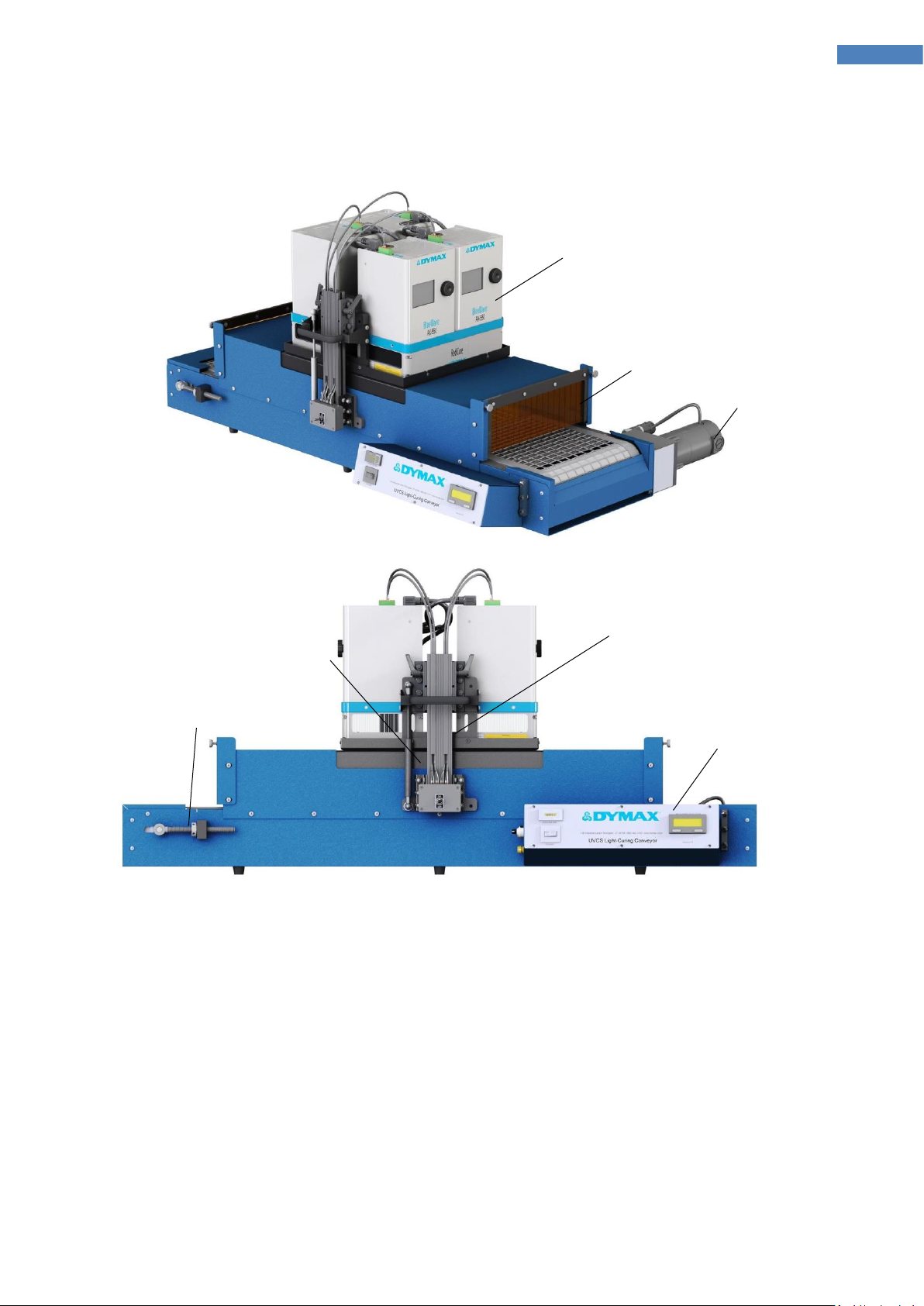
Description of UVCS LED Light-Curing Conveyors..................................................................................................... 5
Assembly and Setup..................................................................................................................................6
Unpacking and Inspecting Your Shipment................................................................................................................6
Parts Included........................................................................................................................................................... 6
Setup ........................................................................................................................................................8
Conveyor Setup ........................................................................................................................................................ 8
Flood System Installation ......................................................................................................................................... 9
Wiring LED Control Switch......................................................................................................................................15
Operating the Conveyor..........................................................................................................................18
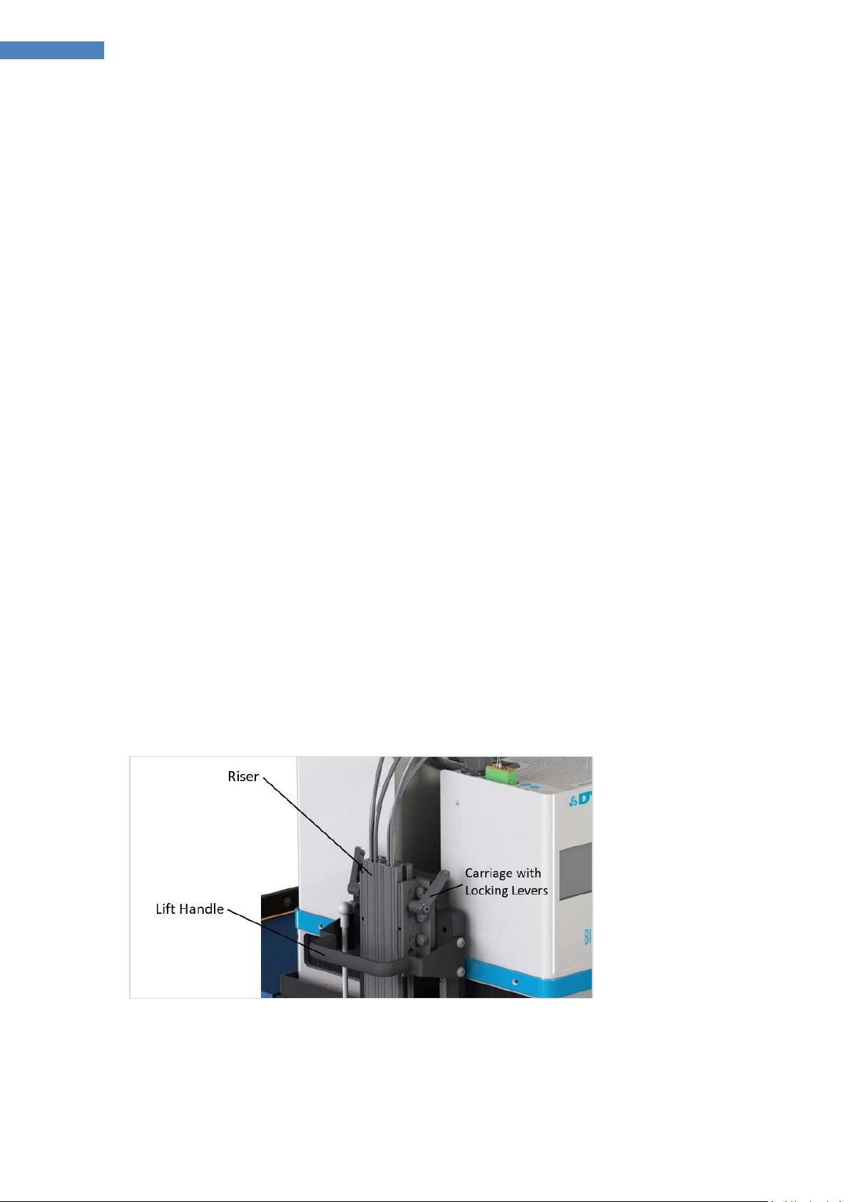
LED System Height Adjustment.............................................................................................................................. 19
Operating the LED Light ..........................................................................................................................21
Operating Modes.................................................................................................................................................... 21
Adjusting Intensity..................................................................................................................................................21
LED Operation ........................................................................................................................................................ 21
Validation ...............................................................................................................................................................22
Cleaning and Maintenance .....................................................................................................................22
Belt-Tracking Adjustment.......................................................................................................................................22
Conveyor Belt Replacement................................................................................................................................... 22
Inspect and Replace Fuses......................................................................................................................................24
Glass Cleaning......................................................................................................................................................... 24
Troubleshooting......................................................................................................................................25
Spare Parts and Accessories....................................................................................................................26
Options/Accessories...............................................................................................................................................26
Spare/Replacement Parts.......................................................................................................................................27
Specifications..........................................................................................................................................28
Definition of Terms .................................................................................................................................29
Warranty ................................................................................................................................................30
Index.......................................................................................................................................................31

4
UVCS LED Light-Curing Conveyor Systems User Guide
Introduction
Introduction to the User Guide
This guide describes how to assemble, use, and maintain Dymax UVCS LED light-curing conveyor systems
safely and efficiently when used with BlueWave® AX-550 arrays.
Intended Audience
Dymax prepared this user guide for experienced process engineers, technicians, and manufacturing
personnel. If you are new to UV light sources and do not understand the instructions, contact Dymax
Application Engineering to answer your questions before using the equipment.
Where to Get Help
Dymax Customer Support and Application Engineering teams are available in the United States, Monday
through Friday, from 8:00 a.m. to 5:30 p.m. Eastern Standard Time. You can also email Dymax at
[email protected]. Contact information for additional Dymax locations can be found on the back cover of
this user guide.
Additional resources are available to ensure a trouble-free experience with our products:
▪Detailed product information on www.dymax.com
▪Dymax adhesive Product Data Sheets (PDS) on our website
▪Safety Data Sheets (SDS) provided with shipments of Dymax adhesives
Safety
WARNING! If you use this UV LED light source without first reading and understanding the
information in the UV Light Safety Guide, SAF001, injury can result from exposure to high-
intensity light. To reduce the risk of injury, please read and ensure you understand the
information in that guide before assembling and operating the Dymax UV LED light source.
Specific safety statements for this device:
This device falls under IEC 62471 Risk Group 3 for UVA and Blue Light emissions:
WARNING. UV emitted from this product. Avoid eye and skin exposure to unshielded
products.
WARNING. Possibly hazardous optical radiation emitted from this product. Do not look at
operating lamp. Eye injury may result.

5
UVCS LED Light-Curing Conveyor Systems User Guide
Product Overview
Description of UVCS LED Light-Curing Conveyors
Dymax UVCS LED light-curing conveyor systems use high-intensity light sources for fast curing of light-
curable materials. UVCS bench-top conveyors can be outfitted with BlueWave® AX-550 LED flood systems
available in one of three different wavelengths (365, 385, or 405 nm). The flood system consists of two
main components: an LED flood array and a power supply that contains the user interface. Up to four LED
flood arrays can be mounted on the conveyor.
BlueWave® AX-550 flood systems feature an intensity adjustment, allowing the output intensity level to
be adjusted from 10 to 100% to meet process and adhesive requirements. LED technology within the
BlueWave® AX-550 allows for instant on/off activation without the need for a warm-up period and is also
rated for continuous operation. A switch on the conveyor is provided to keep the LED array always active.
Fans on the BlueWave® AX-550 provide cooling and must not be covered or blocked. Thermal sensors in
the system shut the unit down to protect the components if the internal temperature exceeds maximum
limits. Please refer to the BlueWave® AX-550 Flood System User Guide for further description and
explanation.
All UVCS conveyors have adjustable belt speeds and lamp-to-belt distance to address a variety of
application requirements. Standard height clearance is from 1.5 to 4.5 inches; optional risers increase
clearance to either 6.5 or 10.5 inches.
Due to the weight of the BlueWave® AX-550 systems, all two and four flood system configurations have a
counterbalance strut installed for ease of height management.
When combined, the UVCS conveyors’ consistent intensity, fast curing, and adjustable line speeds create
an optimized light-curing process that enables high throughput.
Features & Benefits
Features
Complete UV shielding
Built-in exhaust fans with optional stack
Controlled and consistent cure times
Multiple configurations of LED systems available
Accepts parts up to 12" x 36"
Accurate digital belt control and readout
4.5", 6.5", or 10.5" vertical clearance available
Adjustable array-to-belt distance
12" belt width (guides available to channel parts into
center 6")
Bench-top conveyor (with optional transportation carrying
cart)

6
UVCS LED Light-Curing Conveyor Systems User Guide
Assembly and Setup
Unpacking and Inspecting Your Shipment
Your UVCS LED Light-Curing conveyor will arrive in one or two crates. Inspect the crates and boxes for
damage and notify the shipper of box damage immediately.
Open each box and check for equipment damage. If parts are damaged, notify the shipper and submit a
claim for the damaged parts. Contact Dymax so that new parts can be shipped to you immediately.
Check that the parts included in your order match those listed below. If parts are missing, contact your
local Dymax representative or Dymax Customer Support to resolve the problem.
Parts Included
▪UVCS Conveyor with Cradle Assembly installed
▪BlueWave® AX-550 Flood System(s) (Controllers and Emitters)
NOTE: Refer to the BlueWave® AX-550 User Guide for unboxing information
▪UVCS LED Light-Curing Conveyor Systems User Guide (BlueWave® AX-550 Lamps)
▪UV Protection Goggles
▪Accessories Per Custom Orders (exhaust duct, carts, or spare parts)

7
UVCS LED Light-Curing Conveyor Systems User Guide
Figure 1. Conveyor Components
NOTE: Four flood system configuration show.
Drive Motor
Light Curtain
Cradle and BlueWave® AX-550
Systems
Conveyor
Control Panel
Belt Adjustment
Rod
Cradle Riser and
Adjustment Locks
Counterbalance
Strut

8
UVCS LED Light-Curing Conveyor Systems User Guide
Setup
Conveyor Setup
1. Carefully remove all containers from the crate.
2. Remove the conveyor system last to prevent damage to other contents.
3. Remove the protective coverings from the conveyor. Place the conveyor on the conveyor rolling cart
or on a stable work surface.
4. Unpack the BlueWave® AX-550 flood lamp system(s). Each flood lamp system is comprised of a
controller and emitter.
NOTE: It is recommended to assemble each flood lamp system and verify operation prior to
installation onto the conveyor cradle.
Mounting the Flood System(s)
Up to four BlueWave® AX-550 flood systems can be mounted onto your conveyor. The conveyor will be
configured for mounting of the emitter and controller pairs at the factory.
Installation requires the mounting of the emitter first to the cradle and securing with provided fasteners
and then the installation of the controllers onto the emitters with their supplied fasteners.
NOTE: Care must be taken when handling the emitters to protect the glass lens from damage or
contamination.
Preparation
Verify your UVCS conveyor is on a stable platform for all production purposes.
After you have installed your unit, raise the cradle by turning the locking handles and sliding the cradle up
the risers to a convenient working height (Figure 2).
Figure 2. Raise the Cradle to a Convenient Working Height

9
UVCS LED Light-Curing Conveyor Systems User Guide
Flood System Installation
You will need to use the supplied Hex wrench and a small Philips screwdriver to install the BlueWave® AX-
550 systems.
All configurations have the cradle pre-assembled at the factory. Emitters are installed onto the cradle first
and locked in place by screws prior to installing controllers. Some screws attaching controllers to emitters
may not be used.
One Flood System
The emitter may be installed facing either direction, slots are provided on both uprights.
1. Align emitter holes with slots (Figure 3) and install the two screws using hex wrench firmly
(Figure 4).
Figure 3. Align Emitter Holes with Slots
Figure 4. Install Screws Using Hex Wrench
2. Align the controller with the emitter and drop into place ensuring proper alignment to prevent
connector damage (Figure 5).
3. Install the four screws to attach the emitter using Philips head driver firmly.
Figure 5. Align the Controller with the Emitter and Install the 4 Screws

10
UVCS LED Light-Curing Conveyor Systems User Guide
Two Flood System
Two flood system configurations use a dual-emitter base structure to provide the best uniformity of UV
energy at the target. The dual emitter can be configured in perpendicular or in-line with the conveyor
travel direction.
In-Line Dual Emitter
1. Align the emitter base with the cradle opening and lower into place. Insert the supplied screws
and tighten with the hex wrench at four locations.
Figure 6. Lower Emitters into Cradle and Install the Four Screws
2. Next, lower the controllers onto the dual-emitter base, one at a time. Then, fasten each
controller to the emitter base with two screws on each end, using the supplied hex wrench.
Figure 7. Install the Controllers onto to Dual-Emitter Base

11
UVCS LED Light-Curing Conveyor Systems User Guide
Perpendicular Dual-Head Emitter
For the best installation, it is recommended that the dual-head emitter be assembled with two controllers
on the bare cradle.
1. Remove any shielding plates by removing the four mounting screws from the cradle and set
aside.
Figure 8. Remove Shielding Plates
2. Place the dual-head emitter towards the front of the cradle (Figure 9).
Figure 9. Place Emitter Towards Front of Cradle
TOP
VIEW
Remove and
Set Aside

13
UVCS LED Light-Curing Conveyor Systems User Guide
5. Use a screwdriver to tighten the screws and slide the assembly rearward to expose the rear screw
locations.
6. Install the rear screws.
Figure 13. Install Rear Screws
Figure 14. Closeup of Rear Screw
7. Center the BlueWave® AX-550 assemblies in the cradle to allow installation of the blocking plates.
8. Insert the blocking plates and attach them to the cradle with the screws and wrench supplied.
9. Attach the BlueWave® AX-550 emitter to the plates front and back with screws and wrench
supplied.
Figure 15. Attach Emitter to Plates

14
UVCS LED Light-Curing Conveyor Systems User Guide
Four Flood System
1. Lower the two dual head emitters onto the UVCS cradle.
Figure 16. Lower the Dual-Head Emitters
2. Install two screws to hold the emitter to the cradle on either end of the cradle.
Figure 17. Install 2 Screws
3. Lower the controllers onto each emitter carefully.
Figure 18. Lower Controllers on to Each Emitter
4. Install 4 side screws to stabilize the controllers on the emitters.

15
UVCS LED Light-Curing Conveyor Systems User Guide
Figure 19. Install 4 Screws
Figure 20. Closeup of Screw
Wiring LED Control Switch
To control the BlueWave® AX-550’s ON and OFF states for irradiation, connect the trigger wires from the
LED control switch to the TRIGGER pins on the BlueWave® AX-550’s terminal block trigger input. The
terminal block has friction lock wire interface that will accept the crimped ferrule installed on the LED
control wire assemblies by pressing them firmly into place.
Figure 21. Insert Ferrule into Terminal
Figure 22. To Remove a Wire, Use a
Small Screwdriver to Depress the Orange
Lock Tab and Remove the Wire
Terminal Block

16
UVCS LED Light-Curing Conveyor Systems User Guide
Figure 23. Trigger Pins 13 and 14 Installed
Figure 24. LED Control Switch Wiring
LED Control
Wire Assemblies
LED Control
Switch

17
UVCS LED Light-Curing Conveyor Systems User Guide
Figure 25. Top View of BlueWave® AX-550 Showing Terminal Block
Figure 26. Schematic, Control Switch Wiring to Controllers
J1
1823748
1B
2B
1A2A J4
1823748
1B
2B
1A2A
CON_PLC_AX550_1
1
2
3
4
5
6
7
8
9
10
11
12
13
14
15
16
A B
CON_PLC_AX550_2
1
2
3
4
5
6
7
8
9
10
11
12
13
14
15
16
A B
CON_PLC_AX550_3
1
2
3
4
5
6
7
8
9
10
11
12
13
14
15
16
A B
Switch Box
J2
1823748
1B
2B
1A2A
CON_PLC_AX550_4
1
2
3
4
5
6
7
8
9
10
11
12
13
14
15
16
A B
OFF
ON
J3
1823748
1B
2B
1A2A

18
UVCS LED Light-Curing Conveyor Systems User Guide
Operating the Conveyor
The conveyor and the BlueWave® AX-550(s) each have a power cable that needs to be plugged into a wall
outlet. The flood lamps have a power switch located on the top of the unit. The conveyor also has a power
switch, located on the front panel. Plug in all the power cords and turn the conveyor on.
Conveyor belt speeds can be adjusted by turning the speed control knob, located on the side of the
conveyor control panel. Belt speed is indicated on the speed display indicator. The belt speed knob is a
ten-turn potentiometer and is equipped with a lock.
Figure 27. Conveyor Control Panel, Front
Figure 28. Conveyor Control Panel, Side
Belt speed performs two functions when curing.
▪Provides a fixed exposure duration for irradiation of the target
▪Allows fine tuning of cure process when using radiometric measurements

19
UVCS LED Light-Curing Conveyor Systems User Guide
LED System Height Adjustment
The conveyor system uses a simple height management structure using a specially designed cradle and
carriage system for ease of height adjustment. The main parts are shown below.
Figure 29. Height Management Structure
Adjustment
1. For single BlueWave® AX-550 configurations, support the cradle with the handles prior to loosening
the locking levers. For two and four BlueWave® AX-550 configurations, the cradle is supported by
struts to counter the weight and will not require support.
2. To adjust the height, loosen the locking levers on both sides of the riser and on both risers. This will
allow the carriage to slide up and down the riser to the desired heights.
3. Clearance heights that are critical should be set using a measuring device or gauge inside the
conveyor to ensure parts will not hit the inner tunnel.
4. Lift or press down on the handles to move the cradle up and down. Note that the struts will lift the
cradle up on some configurations.
5. Level the heights of both sides of the cradle and tighten the locking levers on both risers firmly to
ensure proper support and unit is locked in place.
6. Remove any measuring devices or gauges prior to starting the system.
7. Verify height setting and clearances prior to starting processes.
Carriage with Locking Levers
Riser
Lift Handle
Cradle

20
UVCS LED Light-Curing Conveyor Systems User Guide
Height Range and Working Distance
Height Range
The conveyor tunnel clearance height maximum is 4.5” (114 mm) when the cradle is all the way up.
When the cradle is all the way down the conveyor tunnel clearance is 1.5” (75 mm).
Working Distance
The distance between the glass lens on the emitter and the belt is called the working distance. Since the
emitter sits flush to the cradle the height adjustment range is also the working distance range.
Parts requiring smaller working distances than 1.5” (75 mm) should be placed on a palette of appropriate
thickness to lift the workpiece off the belt and closer to the emitter.
Figure 30. Cradle Clearance at Minimum & Maximum Height
Cradle at maximum height
Tunnel clearance is 4.5” (114 mm)
Cradle at minimum height
Tunnel clearance is 1.5” (38 mm)
This manual suits for next models
3
Table of contents
Other dymax Accessories manuals
Popular Accessories manuals by other brands

SWEEX
SWEEX MM004PV5 manual

Emerson
Emerson Micro Motion F-Series Sensor installation manual

IFM Electronic
IFM Electronic Efector 200 operating instructions

motif
motif Clean-Z CPAP Ozone Sanitizer quick guide

S+S Regeltechnik
S+S Regeltechnik AERASGARD RFTM-LQ-CO2-Modbus Operating Instructions, Mounting & Installation

TRENDnet
TRENDnet TEG-S24M2C supplementary guide