U S E R G U I D E |U V C - 5 C O N V E Y O R 4
Regulation), VBG (Administrative and Professional
Association), VDE (Association for electrical
engineering) etc. must be observed as well.
However, this device may constitute a hazard if
used improperly by unqualified personnel or for a
purpose other than the intended one.
Only skilled electricians are allowed to work on the
electrical system or components in compliance with
the electro-technical rules (e.g. EN 60204, DIN VDE
0100/0113/0160). The operator has to make sure
that the electrical systems and equipment are
operated and maintained according to the
electrotechnical rules.
In general, it is not allowed to carry out work on
parts under voltage. The protection class of the
device may be IP00 for certain components (direct
contact with hazardous voltage is possible).
Use the device only if it is closed.
Fuses must not be repaired or bridged but only
replaced. Use only fuses according to the circuit
diagram or spare parts list.
Before carrying out repair or maintenance work,
check whether the system is deenergized using a
two-pole voltage tester. Identified defects on
electrical systems/equipment/components must be
eliminated immediately. If there is an acute danger,
the defective device / system must not be operated.
Transport and storage
Transport the device only if packed in the original or
in an appropriate packaging. In case of big devices,
it is recommended to use a transport base or a
pallet for transport.
Store the device in a dry place protected from the
effects of the weather. Avoid exposure of the device
to extreme heat and cold. Observe the transport
instructions in the operating manual.
1. Important General
Information
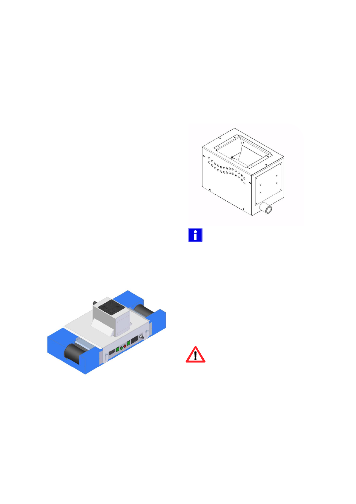
1.1 Scope of Delivery
The scope of delivery includes:
•UV conveyor delivered as desktop device
•UV bulb included in the delivery (number and
doping according to the delivery note)
•Standard 2-meter connecting cable
•Technical documentation according to
order/performance specification
•EC Declaration of Conformity (A) according to
the EC Machinery Directive 2006/42/EC
•Various accessories (see delivery note)
•Safety goggles
Not included in the scope of delivery:
•Ductwork for supply and exhaust air
1.2 Responsibilities
In the following section, the different responsibilities
of the manufacturer and operator are defined.
1.2.1 Responsibilities of the
manufacturer
A risk assessment for this device has been
performed by the manufacturer and the result has
been documented according to DIN EN 12100. The
manufacturer delivers a device which complies with
the EC Machinery Directive 2006/42/EC dated
17 May 2006, appendix II A.
The concept and design of the device correspond
to the basic safety and health requirements of the
EC Machinery Directive; therefore, the device has
received the CE mark and declaration of conformity.
This declaration will cease to be valid if any
modification is made to the device without previous
consultation and consent of Dymax Europe GmbH.
The signed declaration of conformity is a part of this
operating manual, the CE mark has been placed
near the rating plate of the system.