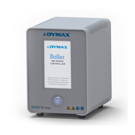
dymax Bluewave MX-MIM User manual

BlueWave®MX-MIM User Guide
Controller for BlueWave®MX-Series Systems
▪Instructions for Safe Use
▪Setup and Operation
▪Maintenance
▪Ordering Spare Parts and Accessories

2
BlueWave® MX-MIM User Guide
The information contained within this guide is subject to change without notice.
© 2019 Dymax Corporation. All rights reserved. All trademarks in this guide, except where noted, are the
property of, or used under license by Dymax Corporation, U.S.A
Please note that most curing system applications are unique. Dymax does not warrant the fitness of the product
for the intended application. Any warranty applicable to the product, its application, and use is strictly limited to
that contained in the Dymax Standard Conditions of Sale. Dymax recommends that any intended application be
evaluated and tested by the user to ensure that desired performance criteria are satisfied. Dymax is willing to
assist users in their performance testing and evaluation by offering equipment trial rental and leasing programs
to assist in such testing and evaluations.

BlueWave® MX-MIM User Guide
3
Contents
Introduction......................................................................................................... 4
Where to Get Help ............................................................................................4
Safety................................................................................................................... 4
Product Overview................................................................................................. 5
Network Data Formats......................................................................................5
Unpacking ............................................................................................................ 5
Parts Included ...................................................................................................5
Connections ......................................................................................................... 6
Input Power.......................................................................................................7
Interlocks...........................................................................................................7
Emitters 1-4.......................................................................................................9
Ethernet Port.....................................................................................................9
Installation......................................................................................................... 10
DIN Rail Mounting (Grounded) .......................................................................10
Factory Reset Button.......................................................................................... 14
Set Up & Web Interface Access........................................................................... 15
Controlling Emitters via the Web Interface.....................................................15
EtherNet/IP........................................................................................................ 18
PROFINET........................................................................................................... 21
Web Guide ......................................................................................................... 23
Log In Page......................................................................................................23
Main Page .......................................................................................................23
Network Configuration Page...........................................................................24
Diagnostics Alarm Log Page ............................................................................25
Diagnostics Page .............................................................................................27
Emitter Control Page.......................................................................................30
Configuration Mode........................................................................................31
Troubleshooting................................................................................................. 41
Parts and Accessories ......................................................................................... 44
Specifications ..................................................................................................... 45
Warranty............................................................................................................ 46

4
BlueWave® MX-MIM User Guide
Introduction
Dymax prepared this user guide for experienced machine control and industrial
automation engineers. Users should be experienced in EtherNet/IP or PROFINET
protocols.
Where to Get Help
Dymax Customer Support and Application Engineering teams are available by phone in
the United States, Monday through Friday, from 8:00 a.m. to 5:30 p.m. Eastern Standard
Dymax locations can be found on the back cover of this user guide.
Additional resources are available to ensure a trouble-free experience with our
products:
▪Detailed product information on dymax.com
▪Dymax adhesive product data sheets on our website
▪Safety data sheets (SDS) provided with shipments of Dymax materials
Safety
WARNING! If you use this UV LED light control injury can result from
exposure to high-intensity light. For UV LED safety guidelines refer to the
safety guide supplied with your MX Series Emitters.

BlueWave® MX-MIM User Guide
5
Product Overview
The BlueWave® MX-MIM UV Curing Controller provides control and monitoring of
Dymax MX-Series Emitters using EtherNet/IP or PROFINET communication to provide
command and control of all functions. This provides a common platform many machine
builders trust to ensure equipment operations and process management with high
speed communications.
It comes in a standard 35mm DIN rail mountable configuration. It supports discrete
safety interlocks for all channels to emitters and a master interlock for full protection.
The system is easily configurable with off the shelf applications and can be integrated
with a large variety of PLC devices to support any level of system complexity.
Network Data Formats
The controller will automatically detect EtherNet/IP or PROFINET connections.
Unpacking
When your BlueWave® MX-MIM arrives, remove all equipment from packaging and
verify contents.
Please retain packing materials in the event the unit needs to be returned. Inspect unit
for any damage or loose parts. Notify Dymax customer service of any issues prior to
installation to prevent damage to associated equipment.
Parts Included
The following items are included with each BlueWave® MX-MIM controller purchase:
■BlueWave® MX-MIM Controller (Qty. 1)
■Interlock Plug, 2 x 5 (Qty. 1)
■Power Plug, 4-Position (Qty. 1)
■USB Drive (Qty. 1)

6
BlueWave® MX-MIM User Guide
Connections
Based on the installation needs, review the connections to be made as part of a planned
installation utilizing any safety features required.
Figure 1. BlueWave® MX-MIM - Top View
Figure 2. Bottom View
Emitter Connectors
1 thru 4
Power
Receptacle
Ethernet Connector
Emitter Interlocks

BlueWave® MX-MIM User Guide
7
Input Power
A 24-volt DC (10A maximum) power supply is connected to the BlueWave® MX-MIM
through the supplied 4-position power plug. The power inputs are reverse-polarity
protected. Two connections each are provided for the +24V and 24V return to allow for
daisy chaining of power input.
Interlocks
The interlock inputs provide a means to interrupt power to an emitter when an interlock
connection is opened. One interlock per emitter is provided. In addition, a master
interlock is provided which will interrupt power to all four emitters when its connection
is opened regardless of the individual emitter interlocks. Upon loss of an interlock
connection, emitter operation will cease, and an alarm will be set. This is a safety
feature that interrupts power to the emitter and does not rely on firmware controls.
Upon restoring the interlock connection, power will be applied to the emitter and it will
be re-initialized but will not activate the UV light until commanded to do so by the user.
Interlock connections are made through the supplied 2 x 5 locking interlock plug, PN
43536. The plug is shipped with jumpers in place to enable operation. A normally closed
switch or a “sinking output, NPN device” may be connected to the desired interlock in
place of the jumpers as illustrated in Figure 3, Figure 4, and Figure 5.
Figure 3. Controlling 4-Emitter Channels with Individual Interlocks

8
BlueWave® MX-MIM User Guide
Figure 4. Controlling 4-Emitter Channels with Master Interlock Alone
Figure 5. All Emitter Channels and Master Interlock Defeated with
Jumpers

BlueWave® MX-MIM User Guide
9
Emitters 1-4
Power and communication are supplied through an emitter interface cable via one of
the four emitter interface connectors located on the front/lower tiered portion of the
enclosure. Please refer to “Parts & Accessories” for available cable lengths. Each cable
connector end provides a screw-down retention feature to ensure positive connections
are maintained during operation.
CAUTION: Power to the controller must be off when connecting or
removing the emitter interconnect cables.
Ethernet Port
One 10/100 EtherNet port provides communications across the user’s network to the
host PLC. The use of shielded cables is required to ensure reliable communications
(Table 1).
Table 1. Communication
LED
Color
Description
Left LED: Speed Indicator
Amber or
Green
Amber ON: Operating as a Gigabit connection
(1000-Mbps)
Green ON: Operating as a 100-Mbps
connection
OFF: Operating as a 10-Mpbs connection
Right LED: Link/Activity
Indicator
Green
Blinking: There is activity on this port
OFF: No link is established

10
BlueWave® MX-MIM User Guide
Installation
DIN Rail Mounting (Grounded)
1. Position the unit below the 35mm DIN rail, with the top tilted slightly outwards, then
lift upwards until the bottom of the DIN rail clip is engaged. (Figure 6)
2. Tilt top of the unit back until the DIN rail rests in the clip, then release. The clips are
spring loaded so they will pull the unit downward slightly and engage the rail.
(Figure 7)
NOTE: 1-inch minimum distance on clearance of vents. The DIN rail must also be
grounded.
Figure 6. DIN Rail Mounting –
Step 1
Figure 7. DIN Rail Mounting –
Step 2
3. Turn OFF the customer-supplied 24V DC supply prior to connecting to unit.
4. Wire the 24V DC supply to supplied power plug. The chassis must be grounded.
5. Insert the power plug PN 43541 into the DC power receptacle (Figure 8)
6. Install the interlock plug, PN 43536 (Figure 9).
7. Configure the interlock plug by removing the pre-inserted jumpers that are not
required based on the Interlocks section of this user guide. Connect the desired
interlock switches as needed.

BlueWave® MX-MIM User Guide
11
Figure 8. Power Plug
Figure 9. Emitter Interlock Plug
8. Plug in the shielded Ethernet Cable(s) to the RJ45 port(s). (Figure 10)
Figure 10. Shielded Ethernet Cable in RJ45 Port
9. Connect the selected emitters to the desired channel connectors. (Figure 11)
CAUTION: Power to the BlueWave® MX-MIM controller must be off
when connecting or removing the emitter interconnect cables.

12
BlueWave® MX-MIM User Guide
Figure 11. Channel Connectors
NOTE: The emitter cables require a minimum bend radius of four inches to ensure the
conductors are not damaged. The minimum clearance distance for the interconnect
harness is five inches (Figure 12). There is 1-inch minimum clearance on vents (Figure
13).
Figure 12. Interconnect Harness Clearance

BlueWave® MX-MIM User Guide
13
Figure 13. Vent Clearance
10. Turn 24V DC supply ON.
11. Review the system front panel LED indicators.
▪Initial state: system health = red, power = green
▪After 15 seconds: system health = green, power = green
NOTE: if indicators are not correct, please refer to the Troubleshooting Section.
Minimum
1-inch
clearance
Minimum 1-inch clearance
Minimum
1-inch clearance

14
BlueWave® MX-MIM User Guide
Factory Reset Button
Figure 14. Factory Reset Button
There is a recessed reset button that can be accessed using a straightened paper clip or
similar device.
If the reset button is pressed for 5 -> 10 seconds and released, the BlueWave® MX-MIM
unit will reset.
If the reset button is pressed for more than 10 seconds and released, the BlueWave®
MX-MIM unit will reset unit and reset to the default IP address 192.168.1.1.
Reset Button

BlueWave® MX-MIM User Guide
15
Set Up & Web Interface Access
Setting Up Network IP Address
NOTE: Pertinent files can be found on the portable USB storage device provided with your
unit. There are two Tech Tips describing applications that can be used to set up an IP
address. Users may employ other methods they are familiar with to set up an IP address.
▪Set up IP address using PRONETA (Tech Tip TT075)
▪Set up IP address using IP Setup (Tech Tip TT076)
Controlling Emitters via the Web Interface
1. Open a web browser and type in the IP address of the desired Dymax device.
2. Login as username: “Admin” and password: “Admin”
3. Verify that the Dymax device main web page opens.
4. Under DIAGNOSTICS, select “Diagnostic Info”.
Figure 15. Diagnostics Menu
5. Select Dymax and click “View”.

16
BlueWave® MX-MIM User Guide
Figure 16. Select Dymax
6. Verify the system status and alarm index are both 0. (Figure 17)
7. To verify the serial number, model type, and firmware revision of your emitter(s)
and controller use the drop-down arrow. These can be compared to the labeling on
each individual device.
8. Select the next emitter from the drop down and click “View”.
9. Repeat for all emitters.
Figure 17. Verify Diagnostics

BlueWave® MX-MIM User Guide
17
10. Under DIAGNOSTICS, select “Dymax Control”.
Figure 18. Diagnostics Menu
11. Verify that all connected emitters can be turned ON/OFF via ON/OFF selection.
Selecting the appropriate radio button on/off, press the Update Emitters Button
and observe the emitter illumination.
12. Verify that the intensity for all connected emitters can be modified via the power
level settings (Figure 19). Adjust power level, press Update Emitters Button and
verify with radiometer that power levels increase or decrease as commanded.
Figure 19. Emitter Controls

18
BlueWave® MX-MIM User Guide
EtherNet/IP
Note: Electronic Data Sheets (EDS) files can be found on the thumb drive provided.
The EDS file conveys the identity information required for a network tool to recognize the
device.
EtherNet/IP Adapter Parameters
Table 2. Input/Output Assemblies Available (Defaults Highlighted)
Instance
Name
CIP Data
Type
Class (Instance 0)
Revision
UINT
Max instance
UINT
101 (0x65)
T2O (Input) Controller + 4 Emitters
(See Table 4 for bytes 0 to 115)
USINT[116]
113 (0x71
O2T (Output) Controller + 4 Emitters
(See Table 3 for bytes 0 to 7)
USINT[8]
198 (0xC6)
Input only heartbeat
Heartbeat
199 (0xC7)
Listen only heartbeat
Heartbeat
Unused (n)
Configuration

BlueWave® MX-MIM User Guide
19
Table 3. O2T (Output) Assembly Data Format
Byte
Data
Type
Description
(Command –Field)
Value Reference
0
BYTE
Set emitter LED state
Bit 0: Emitter 1
…
Bit 3: Emitter 4
Turn emitter LED ON/OFF
Bit set to 1 == ON
Bit set to 0 == OFF
1
SINT
Reset Unit
Transition from 0 to 1 will reset the unit
2
SINT
Reset Alarms
Transition from 0 to 1 will reset alarm state
3
SINT
Reserved
4
SINT
Set Emitter 1 Power
Level –Power Level
Set Emitter 1 Power Level (1-100)
5
SINT
Set Emitter 2 Power
Level –Power Level
Set Emitter 2 Power Level (1-100)
6
SINT
Set Emitter 3 Power
Level –Power Level
Set Emitter 3 Power Level (1-100)
7
SINT
Set Emitter 4 Power
Level –Power Level
Set Emitter 4 Power Level (1-100)

20
BlueWave® MX-MIM User Guide
Table 4. T2O (Input) Controller + 8 Emitters Data Format
Byte
Data
Type
Description
(Command –Field)
Value Reference
0-3
SINT[4]
Echo DataEch
4
SINT
Get Controller Status –
System Status
0 == No Alarms;
1 == MINOR Alarm;
2 == MAJOR Alarm
5
SINT
Get Controller Status –
Alarm Index
See Table 9 for Specific Alarm
Details
6-7
SINT[2]
Reserved
8-11
REAL
Get Controller Status –
MaxTemp
Controller Maximum
Temperature Ever Recorded
12-15
REAL
Get Controller Status –
Temp
Controller Present
Temperature
16-19
REAL
Get Controller Status –Volts
Controller Present 12V Reading
20
SINT
Get Emitter 1 Status –
Alarm Index
See Systems Alarms Section
for Specific Alarm Details
21
SINT
Get Emitter 1 Status –
Set Fan Speed
0 - 100%
22
SINT
Get Emitter 1 Status –
LED State
0 == LED is OFF;
1 == LED is ON
23
SINT
Get Emitter 1 Status –
Power Level
Emitter Present Power Level
Setting
24-27
REAL
Get Emitter 1 Status –
Max Temp
Emitter Maximum
Temperature Ever Recorded
28-31
REAL
Get Emitter 1 Status –Temp
Emitter Present Temperature
32-35
REAL
Get Emitter 1 Status –
Max Current
Emitter Maximum Current
Draw Ever Recorded
36-39
REAL
Get Emitter 1 Status –Current
Emitter Present Current Draw
40-43
SINT[4]
Emitter 1 Reserved
44-67
SINT[24]
Emitter 2
See Emitter 1 (Bytes 20 -43)
68-91
SINT[24]
Emitter 3
See Emitter 1 (Bytes 20 -43)
92-115
SINT[24]
Emitter 4
See Emitter 1 (Bytes 20 -43)
Table of contents
Other dymax Controllers manuals