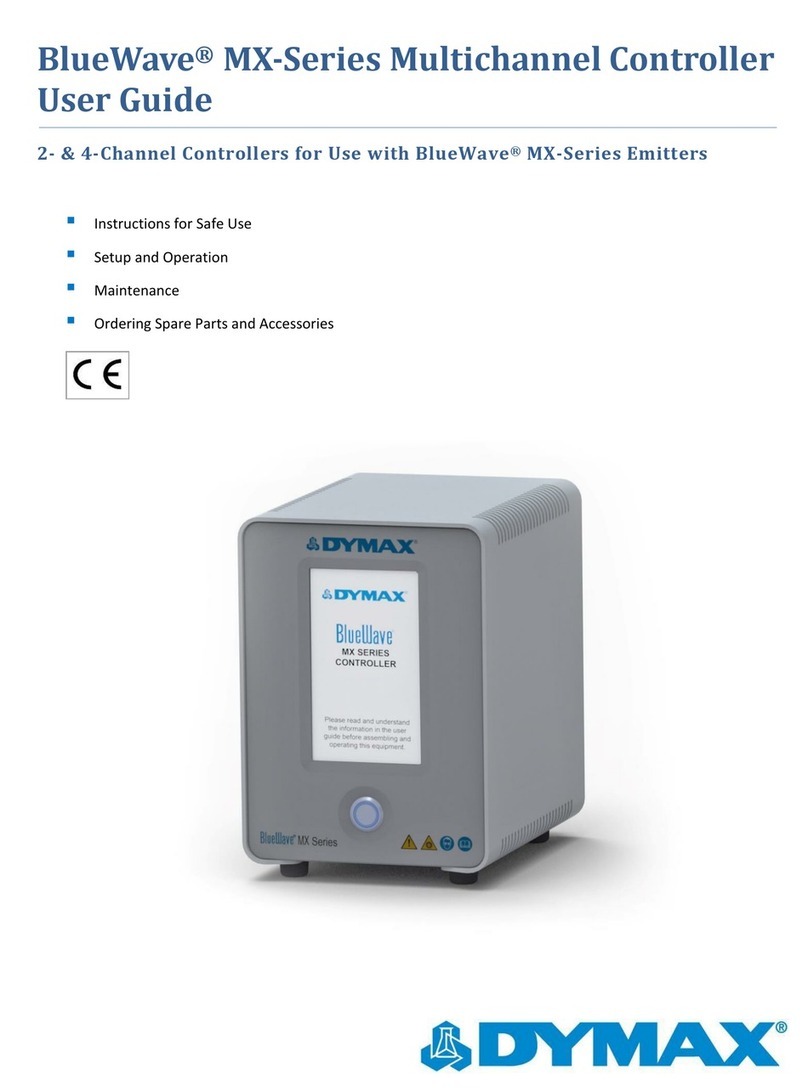
dymax BlueWave MX-Series User manual

BlueWave® MX-Series
1-Channel Controller
User Guide

2 U S E R G U I D E |B L U E W A V E M X - S E R I E S 1 C H C O N T R O L L E R
About Dymax
Light-curable adhesives. Systems for light curing, fluid
dispensing, and fluid packaging.
Dymax manufactures industrial adhesives, light-curable adhesives,
epoxy resins, cyanoacrylates, and activator-cured adhesives. We
also manufacture a complete line of manual fluid dispensing
systems, automatic dispensing systems, and light-curing systems.
Light-curing systems include LED light sources, spot, flood, and
conveyor systems designed for compatibility and high
performance with Dymax adhesives. Dymax adhesives and light-
curing systems optimize the speed of automated assembly, allow
for 100% in-line inspection, and increase throughput. System
designs enable stand-alone configuration or integration into your
existing assembly line.
Please note that most dispensing and curing system applications
are unique. Dymax does not warrant the fitness of the product for
the intended application. Any warranty applicable to the product,
its application, and use is strictly limited to that contained in the
Dymax standard Conditions of Sale. Dymax recommends that any
intended application be evaluated and tested by the user to ensure
that desired performance criteria are satisfied. Dymax is willing to
assist users in their performance testing and evaluation. Data
sheets are available for valve controllers or pressure pots upon
request.

U S E R G U I D E |B L U E W A V E M X - S E R I E S 1 C H C O N T R O L L E R 3
Contents
Introduction............................................................... 4
Where to Get Help............................................................ 5
Safety......................................................................... 5
Product Overview ..................................................... 6
Description of BlueWave MX-Series 1CH Controller... 6
Controller Front Panel...................................................... 7
Controller Back Panel ...................................................... 8
Unpacking.................................................................. 9
Parts Included ................................................................... 9
System Setup ............................................................ 9
System Connections ........................................................ 9
Modes of Operation .................................................. 11
Manual Mode .................................................................... 11
Timer Mode....................................................................... 11
PLC (Programmable Logic Controller) Operation........ 12
Examples of PLC Wiring ........................................... 15
Operation................................................................... 17
Control Screen.................................................................. 18
Irradiation........................................................................... 20
Saving Programs .............................................................. 21
System Settings ........................................................ 21
Language Settings ........................................................... 22
Volume Settings................................................................ 22
Brightness Settings .......................................................... 23
User Settings/Boot Modes .............................................. 23

4 U S E R G U I D E |B L U E W A V E M X - S E R I E S 1 C H C O N T R O L L E R
System Information................................................... 24
Troubleshooting & Maintenance.............................. 25
Measuring/Checking Intensity ........................................ 25
Product Cleaning.............................................................. 25
Alarms................................................................................ 25
Accessories ............................................................... 27
Spare Parts ................................................................ 27
Specifications............................................................ 28
Validation................................................................... 29
Set Exposure Time, Determine Intensity....................... 29
Set Intensity, Determine Exposure Time ....................... 29
Control ............................................................................... 29
Declaration of Conformity ........................................ 30
Warranty .................................................................... 31

U S E R G U I D E |B L U E W A V E M X - S E R I E S 1 C H C O N T R O L L E R 5
Introduction
This guide describes how to set up, use, and maintain BlueWave®MX-Series Systems
using a 1-Channel (CH) Controller safely and efficiently.
Intended Audience
This user guide is meant for experienced process engineers, technicians, and
manufacturing personnel. If you are new to high-intensity LED light sources and do not
understand the instructions, contact Dymax Application Engineering for answers to your
questions before using the equipment.
Where to Get Help
Customer Support and Applications Engineering teams are available by phone and
email in Germany, Monday through Friday, from 8:00 a.m. to 5:00 p.m. Central
Please see the back cover for worldwide contact information.
Additional resources are available to ensure a trouble-free experience with our
products:
•Detailed product information on dymax.com
•Dymax adhesive product data sheets on our website
•Safety data sheets (SDS) provided with shipments of Dymax materials
Safety
WARNING! If you use this UV LED light control without first reading
and understanding the information in the Safety Guide SAF001, injury can
result from exposure to high-intensity light. To reduce the risk of injury,
please read and ensure you understand the information in that guide before
assembling and operating the Dymax UV LED light system.

6 U S E R G U I D E |B L U E W A V E M X - S E R I E S 1 C H C O N T R O L L E R
Product Overview
Description of BlueWave MX-Series 1CH Controller
BlueWave MX-Series Controller when combined with MX Series emitters feature all the
benefits of LED-curing technology in smaller, more versatile units. These systems are
uniquely designed to offer higher, more consistent curing intensity than traditional spot
or flood curing systems. The systems are comprised of a power supply, a controller
with an easy-to-use control interface, and a high intensity emitter.
The system can be truly tailored to users’ curing needs – allowing them to choose from
any of the different emitter types and different wavelength LED emitters (365, 385, or
405 nm) in three cure pattern formats; spot, mini-flood and line emission patterns. This
flexibility ensures optimal cures are achieved across a variety of bond-line geometries.
Users also have endless set up flexibility; for automated curing processes, the emitter
can be easily mounted machine arms or further from the controller without fear of
intensity variations. When used as a bench-top curing system, the unit can be paired
with a stand and shielding or a lightguide can be connected to the system for
specialized applications when paired with MX spot emitters.
•The BlueWave®MX-150 functions as a high-intensity spot-curing system. The
system has the ability to be set up in many configurations and can be used with a
lightguide if needed.
•The BlueWave®MX-250 functions as a flood-curing system with a 50 mm x 50
mm (2 in x 2 in) active curing area. It provides manufacturers with additional
curing flexibility and expansion capabilities BlueWave MX-Series emitters can be
used as hand-held units or integrated into an automated manufacturing system
allowing for maximum application flexibility. Their output intensity levels can also
be adjusted from 1% to 100% to meet process and adhesive requirements.
BlueWave MX-Series 1CH systems are rated for continuous operation. However, if
the internal temperature of the system exceeds the maximum safe operating
temperature limits, each emitter contains a thermal sensor that will shut the unit
down to protect the components of the emitter.
•The BlueWave®MX-275 functions as a line pattern flood-curing system with a 5
mm x 50 mm (0.2 in x 2 in) asserted curing area.

U S E R G U I D E |B L U E W A V E M X - S E R I E S 1 C H C O N T R O L L E R 7
Controller Front Panel
The front panel features the power button and a touchscreen display through which the
unit can be operated.
Power Button —Press the power button to power up the controller. Press the button a
second time to turn the unit off.
Figure 1.
Front Control Panel
Touch
Screen
Display
Power
Button

8 U S E R G U I D E |B L U E W A V E M X - S E R I E S 1 C H C O N T R O L L E R
Controller Back Panel
Power Cord Receptacle —Connection point for the power cord.
Foot Pedal Jack —Connection point for the foot pedal.
PLC Connector Terminals —Connection points for an interface with a user-supplied
PLC (for remote operation).
Emitter Connector —Connection point for the system’s emitter.
Figure 2.
Back Panel Controls & Connections
Emitter
Connector
PLC Input &
Output
Connection
Terminals
Foot
Pedal
Jack
Power Cord
Receptacle

U S E R G U I D E |B L U E W A V E M X - S E R I E S 1 C H C O N T R O L L E R 9
Unpacking
Upon arrival, inspect all boxes for damage and notify the shipper of box damage
immediately. Open each box and check for equipment damage. If parts are damaged,
notify the shipper and submit a claim for the damaged parts. Contact Dymax so that
new parts can be shipped to you immediately.
The parts below are included in every package/order. If parts are missing from your
order, contact your local Dymax representative or Dymax Customer Support to resolve
the problem.
Parts Included
•Controller
•Power Supply
•Emitter Cable
•Power Cord
•Foot Pedal
•Safety Glasses
•BlueWave MX-Series 1CH User Guide
System Setup
System Connections
NOTE: Although this product is designed with protection against ESD (Electrostatic
Discharge) it is recommended to take precautions against static when handling the
BlueWave MX-Series controller or LED emitter independently. Once these devices are
attached together through the interconnect cable, then the threat of ESD damage is
eliminated.
1. Attach the Power Cord to the Power Cord Receptacle located on the unit’s back
panel (Figure 2).
2. At the top of the Controller’s Rear Panel, there is a connector labeled “Emitter”
(Figure 4). Connect one end of the Emitter Cable to this connector and the other
end to the Emitter.

10 U S E R G U I D E |B L U E W A V E M X - S E R I E S 1 C H C O N T R O L L E R
WARNING! Under no circumstance should the interconnect cable from the
BlueWave MX-Series 1CH controller to the LED emitter be connected or
disconnected while power to the unit is on. This procedure is usually called “hot-
swapping” and should not be performed as it could cause damage to the controller
or the LED emitter. Always power down the equipment before disconnecting any of
these devices.
3. Plug the opposite end of the Power Cord into an appropriate AC outlet. The unit is
now powered and ready to be turned on with the On/Off Switch located on the front
of the unit (Figure 3).
WARNING! If the BlueWave MX-Series 1CH controller is powered on with no
LED emitter connected, the controller screen will not show the banner containing
the information of the emitter type or wavelength. An error will appear on the
display and an audible alarm will sound. Power down the controller, connect the
LED emitter, then power on again and the banner will appear.
4. If using the optional foot pedal, plug it into the foot pedal jack on the rear panel of
the controller.
If you are using a PLC - There are input and output PLC Connection Terminals that
can be used to integrate the unit to an automated assembly line. The input
connections consist of PLC Enable, Emitter Interlock, Light Shield Sensor,
Program/Analog, and LED On. The unit normally has high logic levels (24V) and
looks for a low signal (0V) input. The 24VDC is supplied internally allowing use of a
simple contact closure such as a switch or relay to actuate the inputs.
The output PLC connection terminals consist of System Status, LED status and
Reserved. These output signals are 24VDC inactive and 0 Volts active.
The Analog intensity input is a 0 –10 Volt input that controls the LED intensity. This
function is active when the Prog/Analog and PLC Enable inputs are activated.
Refer to Table 1 for more complete description of PLC input and outputs.
5. Your unit is now ready for operation.

U S E R G U I D E |B L U E W A V E M X - S E R I E S 1 C H C O N T R O L L E R 11
Modes of Operation
The system has three basic modes of operation: manual, timer, and PLC.
Manual Mode
In manual mode, the LED is energized when the foot pedal is pressed, passing curing
energy through the delivery optics, and de-energized when the foot pedal is released.
The LED may also be energized by momentarily pressing the run/stop button located in
the center of the touchscreen user interface. The LED will be energized to the power
level set through the touchscreen user interface. Pressing the run/stop button again
during the curing cycle will de-energize the LED.
When manual mode is selected, the time indicator will be initialized to zero. The time
display will count up during an exposure and display the total elapsed time at the end of
the exposure to allow the user to save the time and power values if desired. Starting a
new manual exposure will reset the time value to zero immediately and proceed to
count up.
Timer Mode
In timer mode, the LED is energized for a specific time period each time the foot pedal
or run button is pressed. The specific time is set by adjusting the timer’s value through
the touchscreen user interface. Momentarily pressing the foot pedal or run button starts
the timer and energizes the LED. When the timer counts down to zero, the LED is de-
energized, and no curing energy is emitted. The timer is reset to the pre-set value, and
the system is immediately ready to run another exposure cycle. The LED can be de-
energized at any time during the curing cycle by simply pressing the run/stop button.

12 U S E R G U I D E |B L U E W A V E M X - S E R I E S 1 C H C O N T R O L L E R
PLC (Programmable Logic Controller) Operation
When in PLC mode, an external PLC can control the
unit. The PLC provides input signals to the BlueWave
MX-Series 1CH system to control the on/off signals and
intensity of the LED. The PLC monitors the status of the
system by reading output signals provided by the unit.
The PLC is typically programmed to start other
machinery when the BlueWave MX- Series 1CH system
becomes ready, or something starts the unit when other
machinery is ready. The input and output signals are
present on connector (J5) located on the back of the
unit.
Figure 3.
PLC Mode Screen
Figure 4.
PLC Inputs & Outputs
J
8
J6
J
5
1
3
5
7
9
2
4
6
8
10
1
3
5
2
4
6
1
2
40mA Max Sinking*
(Not Sourcing)

U S E R G U I D E |B L U E W A V E M X - S E R I E S 1 C H C O N T R O L L E R 13
Table 1. PLC Inputs
Signal Name / Description
Isolated Inputs/
Outputs
Connector-Pin
Signal Level
Signal
GND
Active
Inactive
PLC INPUTS
PLC ENABLE
Active: Unit enters PLC mode and displays the
PLC input status screen. The touch screen input
is ignored.
Inactive: All dedicated PLC inputs are ignored,
and the PLC outputs will remain active.
IN
1
2
0
VDC
24 VDC
EMITTER INTERLOCK
Asserting this signal enables the emitter.
Momentarily breaking the connection via
customer supplied relays or switch contacts will
deactivate the emitter. Switch contacts
incorporated into access doors on light shield
type enclosures will stop energy emissions if the
door is opened during an exposure cycle.
IN
3
4
0
VDC
24 VDC
LIGHT SHIELD SENSOR
Active: The LED will be enabled (able to accept
either LED ON IN or FOOT PEDAL IN).
Inactive: The LED will be disabled.
IN
5
6
0
VDC
24 VDC
PROG/ANALOG
Active: The internal programmed time/power
settings will be used.
Inactive: The external analog intensity input
(PLC ANALOG IN) will be active and require a
voltage at the ANALOG INTENSITY input pins.
IN
7
8
0
VDC
24 VDC
LED ON
Manual operation: The LED turns on while the
signal is active.
Automatic operation: The LED turns on for the
programmed time duration upon signal
activation.
The timed cycle must complete before another
signal activation is recognized.
IN
9
10
0
VDC
24 VDC
NOTE: When you initiate PLC mode you have the option to toggle
PROG/ANALOG(EXT). PROG will use the program that has been selected via the

14 U S E R G U I D E |B L U E W A V E M X - S E R I E S 1 C H C O N T R O L L E R
MANUAL input interface GUI. Ensure you are in Manual Mode prior to switching to PLC
mode.
ANALOG(EXT) mode you can control the intensity via the analog intensity input J6
(1VDC = 10% intensity, 7VDC = 70%, etc) and have your PLC output manage the
exposure time by asserting the LED ON command. For the best performance,
especially when using very short exposure times, EXTERNAL PLC control is suggested
to minimize latency found when using either MANUAL or TIMER mode.
Table 2. PLC Outputs & PLC Analog In
Signal Name / Description
Isolated Inputs/
outputs
Connector-Pin
Signal Level
Signal
GND
Active
Inactive
PLC OUTPUTS
SYSTEM STATUS
Active: Indicates the system is healthy.
Inactive: Indicates that the system has one or
more operational problems.
OUT
1
2
0
VDC
24
VDC
LED STATUS
Indicates LED is commanded on. The LED "On"
status will stay in OFF state when in error
condition.
OUT
3
4
0
VDC
24
VDC
RESERVED
No Connection
5
6
PLC ANALOG IN
ANALOG INTENSITY
Analog signal applied to this input to control the
LED intensity. (1.0V = 10% intensity) **
IN
1
2
0 to 10 VDC
**A ferrite will be required on the PLC (0-10V) analog input cable to reduce noise. Ferrite bead (PN
0443164251) installed on the analog PLC cable (looped once) at the termination end.

U S E R G U I D E |B L U E W A V E M X - S E R I E S 1 C H C O N T R O L L E R 15
Examples of PLC Wiring
Figure 5.
PLC Interface Using Dry Contact Switches or Relays
Figure 6.
PLC Analog Control Input
Figure 7.
PLC Discrete Status Outputs

16 U S E R G U I D E |B L U E W A V E M X - S E R I E S 1 C H C O N T R O L L E R
Figure 8.
PLC Interface Using n-Channel Mosfets or Relays
Note: The PLC status outputs have a maximum sink current of 5 mA each. It is
recommended to use a solid-state relay with a control current <5 mA.
Recommended Relays: Weidmuller 8820710000, Phoenix Contact 2980636

U S E R G U I D E |B L U E W A V E M X - S E R I E S 1 C H C O N T R O L L E R 17
Operation
To operate the system, first verify that all Connectors are correctly plugged into the rear
panel of the unit (See System Connections, pg. 9 for more details). When all
Connectors are properly plugged in, press the Power Button on the front panel of the
unit. The system is now ready for use.
NOTE: The following lightguide instructions apply to the MX-150 emitter operation only.
The MX-250 emitter emits a flood pattern, so lightguide references are not applicable to
this unit.
The insertion of the 5-mm lightguide adapter, or an actual lightguide, into the end of the
LED emitter needs to be fully seated. The device utilizes 3 spring plungers inside to
hold the lightguide in place. Excessive vibration may cause the lightguide to shift
position and cause an error condition. End users must provide means through the use
of a fixture or other device to address this situation.
Upon startup of the unit, an intro screen will appear. After 4 seconds, the control screen
should appear in the display. It will be in administrator mode the first time the unit is
started.

18 U S E R G U I D E |B L U E W A V E M X - S E R I E S 1 C H C O N T R O L L E R
Control Screen
The control screen is used to set up and run curing cycles. This screen allows users to
switch back and forth between administrator and production modes as well as between
timer and manual operating modes. It is also where the cycle’s time and power settings
are set.
Figure 9.
Control Screen Components
Information Button —Loads the system information screen. Refer to “System
Information” on page 24 for more information.
Administration/Production Mode Toggle —Switches between administration and
production modes. A password will be required to enter administrator mode. Refer to
User Settings/Boot Modes for more information.
The production screen layout is identical to the administrator screen. The time, power
and mode settings reflect the administrator settings and cannot be altered. User
operational controls are limited to “Run/Stop”, “Volume” and “Brightness” (see Settings
screen). Program(s) names will be displayed along with the Emitter type but the ability
to save and load Program(s) will be disabled. The default password is 1234.
Settings Button —Loads the settings screen where the volume, language, screen
brightness, and other user settings can be adjusted. Refer to “System Settings” on
page 24 for more information.
Irradiating Time
Operation
Mode
Information
Button
Settings Button
Power Button
Run/Stop Cycle
Button
Emitter Type
Program Button
Alarms Icon
Admin/Production
Modes Toggle

U S E R G U I D E |B L U E W A V E M X - S E R I E S 1 C H C O N T R O L L E R 19
Irradiating Time —The Irradiating time is displayed in this field.
When in timed mode, time is entered by touching the display field which in turn brings
up a numerical keypad for entry. The entry range is 0.1 –999 seconds. From 0.1 –30
seconds the adjustment is made in 0.1 second increments and from 30 –999 seconds
the adjustment is made in 1 second increments.
When in manual mode, time is displayed, and entry is not available.
Power Button —The Irradiating power level is displayed in this field. The power level
is entered by touching the field which in turn brings up a numerical keypad for entry.
The power range is 1 to 100% in increments of 1%. Entering a decimal will result in
rounding to the lowest whole number.
Run/Stop Cycle Button —Initiates/terminates an exposure. The button also functions as
an indicator which informs the user that the irradiator is emitting curing energy.
Operation Mode —Select from timer or manual mode. For more information on
operating modes, refer to “Modes of Operation” on page 11.
Alarms Icon —Alerts the user that there is an error. Refer to page 25 for more
information.
Emitter Type —Identifies the emitter model connected to the controller and the
wavelength that it provides. Emitters are available in two models, the MX-150 spot and
the MX-250 flood. Each model is also available in three wavelengths: RediCure®(365
nm), PrimeCure®(385 nm), and VisiCure®(405 nm).
Program Button —Loads a list of saved curing programs to choose from.

20 U S E R G U I D E |B L U E W A V E M X - S E R I E S 1 C H C O N T R O L L E R
Irradiation
To run a curing cycle in manual mode:
1. Input the power value by pressing the respective field. The time field will be
disabled.
2. Press the Run Button or Foot Pedal to start the irradiation. The timer field will begin
counting. The irradiation will terminate when the Stop Button is pressed or Foot
Pedal is released.
The time delay for PLC or Foot pedal activation and the LED turning on is 260 ms.
When in PLC Program mode only: Add 225 ms to the LED ON in signal (J5) on the
PLC connector. For example –if the user desires to turn the LED on for 1 second
then the LED ON in signal (through J5) should be 1.225 sec.
To run a curing cycle in timer mode:
1. Input the time and power values by pressing on each respective field or by loading a
previously saved program. To load a curing program, press the Program Button on
the bottom of the screen. A list of available programs will appear. Select the
appropriate one and press “LOAD”. The program will load and you will be brought
back to the Control Screen.
2. Press the Run Button or Foot Pedal to start the timed irradiation. The irradiation will
terminate when the count reaches zero. The timed exposure may be aborted at any
time by pressing the Stop Button. Foot Pedal reactivation will not terminate the
cycle.
At the conclusion of the timed exposure, the time value will be automatically
reloaded in preparation for the next activation. Although the user is allowed to enter
a time of 0.0 seconds, note that the LED will not activate since there is essentially no
time set for it to run. The BlueWave MX-Series 1CH system will however support
accurate LED activation as short as 0.1 seconds.
It is possible for users to type in a time setting greater than 4 digits during time
entry. However, the BlueWave MX-Series 1CH system will only support up to 999
seconds and will default to this value if anything higher than that is entered.
Other manuals for BlueWave MX-Series
4
This manual suits for next models
2
Table of contents
Other dymax Controllers manuals