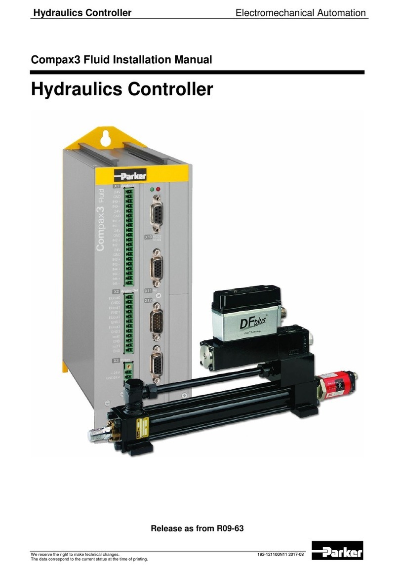
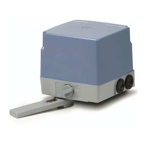
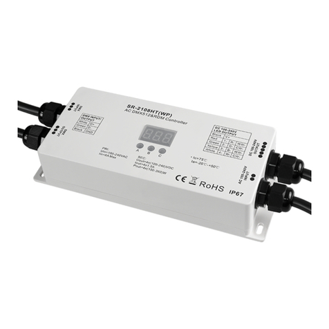
OSKAR ratiotherm rZR16x2 Technical manual

Technical document
Central controller rZR16x2
Version 15.06.2021-wi
0 - 10V
Auto - O - Hand
I
O
230V
Hand - O - Auto
Netz

TU_Central controller 16x2-2021-06-wi - Errors and omissions excepted. All informaon, pictures and drawings are subject to change.
Compliance with the generally applicable and recognised rules of technology must be observed at all mes!
CAUTION: Installaon and wiring may only be carried out by authorised specialists.
2
TABLE OF CONTENTSTABLE OF CONTENTS
SENSOR 4
OPTIONAL ACCESSORIES 5
TECHNICAL DATA 6
MOUNTING THE CONTROLLER CONSOLE 7
ASSEMBLY / DISASSEMBLY OF THE CONTROLLER 8
SENSOR POSITIONING IN THE VERTICAL IMMERSION SLEEVE 9
SENSOR POSITIONING FOR HOT WATER PREPARATION 10
WIRING THE COMPONENTS 12
WIRING THE COMPONENTS 13
OVERVIEW OF THE OUTPUTS 14
MOTHERBOARD/PLATE UPPER SECTION 15
Standard programming 18
Inputs (node 1) for standard hydraulics V4/04 19
Outputs (node 1) for standard hydraulics V4/04 20
DL inputs 21
CABLE SELECTION AND NETWORK TOPOLOGY 22
HYDRAULIC CALIBRATION OF THE SOLAR COMPACT STATION SOK 34
PROBLEM SOLVING 46
PROBLEM SOLVING 47
RATIOTHERM SERVICE CONSIGNMENT NOTE 48
GUARANTEE STATEMENT 49

3
TU_Central controller16x2-2021-06-wi - Errors and omissions excepted. All informaon, pictures and drawings are subject to change.
Compliance with the generally applicable and recognised rules of technology must be observed at all mes!
CAUTION: Installaon and wiring may only be carried out by authorised specialists.
SAFETY REGULATIONS
intended exclusively for authorised specialists.
when it is de-energised.
Use contrary to the intended purpose leads to the exclusion of any liability claims.
•
•
•
•
•
•
•
•
•
• -
-
tened with gentle alcohol (e.g. spirit) should be used for cleaning.
The unit therefore has no adjustment facility.
Thus, a possible adjustment is not necessary.
Any repair must not alter the design features of the appliance. Spare parts must corres-
pond to the original spare parts and must be used again in accordance with the factory

TU_Central controller 16x2-2021-06-wi - Errors and omissions excepted. All informaon, pictures and drawings are subject to change.
Compliance with the generally applicable and recognised rules of technology must be observed at all mes!
CAUTION: Installaon and wiring may only be carried out by authorised specialists.
4
SENSOR
• PT 1000 B (-40 bis +180°C)
• 5 m Silicone cable
• Sensor Ø 5,5 mm
Collector sensor
• PT 1000 B (-40 bis +180°C)
• 2,5 m Silicone cable
• Sensor Ø 5,5 mm
• Surge protecon
Pipe contact sensor
• PT 1000 B (-40 bis +180°C)
• 5,0 m Silicone cable
• Fastening clamp
• Heat-conducng paste
• PT 1000 B (-40 bis +180°C)
• 5 m PVC-Cable
• Brass screw-in part ½“ AG
Outdoor sensor
• PT 1000 B (-40 bis +180°C)
• Surge protecon

5
TU_Central controller16x2-2021-06-wi - Errors and omissions excepted. All informaon, pictures and drawings are subject to change.
Compliance with the generally applicable and recognised rules of technology must be observed at all mes!
CAUTION: Installaon and wiring may only be carried out by authorised specialists.
OPTIONAL ACCESSORIES
Room setpoint adjuster RSG-Plus
• DL bus device
• Potenometer (±5°C)
• Operang mode selector switch
Room remote control
•
unit for room temperature, humidity and air pressure.
Extension module RSM 610
•• with 6 inputswith 6 inputs
•• with 6 outputs (switching output or mixer control) with 6 outputs (switching output or mixer control)
•• with 4 outputs (0-10 Volt or PWM) with 4 outputs (0-10 Volt or PWM)
•• with sensors as requiredwith sensors as required
C.M.I. Modul
• The C.M.I. (Conrol and Monitoring Interface) is an interface for the comfortable
remote control, data logging and visualisaon of all ra controllers with a
of all ra controllers with DL or CAN bus.
Electronic volume flow sensor EVS
•• DN 10: ow rates between 2.0 and 32 litres per min.DN 10: ow rates between 2.0 and 32 litres per min.
•• DN 15: ow rates between 4.0 and 50 litres per min.DN 15: ow rates between 4.0 and 50 litres per min.
•• DN 20: ow rates between 5.0 and 85 litres per min.DN 20: ow rates between 5.0 and 85 litres per min.
•• DN 25: ow rates between 9.0 and 150 litres per min.DN 25: ow rates between 9.0 and 150 litres per min.
•• Detecon of medium temperatures from -40 to +125°C (PT1000)Detecon of medium temperatures from -40 to +125°C (PT1000)
•• Output of the measured values via DL busOutput of the measured values via DL bus
Volume flow pulse transmitter VIG1 or VIG2
•• Impeller meter for exact recording of the volumetric ow with Impeller meter for exact recording of the volumetric ow with
pulse output.pulse output.
•• Temperature range up to 90°C Temperature range up to 90°C
•• Pulse output potenal-free - maximum load 10 mA for rZR16x2 for exact heat Pulse output potenal-free - maximum load 10 mA for rZR16x2 for exact heat
quanty measurement e.g. of a solar systemquanty measurement e.g. of a solar system

TU_Central controller 16x2-2021-06-wi - Errors and omissions excepted. All informaon, pictures and drawings are subject to change.
Compliance with the generally applicable and recognised rules of technology must be observed at all mes!
CAUTION: Installaon and wiring may only be carried out by authorised specialists.
6
TECHNICAL DATA
All inputs
Temperature sensors of the types PT1000 (standard sensor for ratiotherm), KTY 10 (2 kΩ/25°C),
KTY 10 (1 kΩ/25°C), PT100, PT500, Ni1000, Ni1000TK5000 and room sensors RAS or RASPT,
radiation sensor GBS01, thermocouple THEL, humidity sensor RFS, rain sensor RES01,
pulses max. 10 Hz, voltage up to 3.3V DC, resistance (1-100kΩ), and as digital input
Entrance 7 addional voltage (0-10 Volt DC)
Entrance 8 addional current loop (4-20 mA DC), voltage (0-10 volts DC)
Entrance 15, 16 Addional pulse input max. 20 Hz, e.g. for volumetric ow transmier VIG or SO signals
To avoid uctuaons in the measured values, ensure that the sensor cables are not exposed to
external negave inuences from 230V cables to ensure interference-free signal transmission. The
sensor lines must not be routed together with the mains voltage in one cable. If unshielded cables are
a minimum distance of 5 cm. Sensor lines for PT100 or PT500 sensors must be shielded. All sensor
Outputs
1, 2, 3, 4, 6, 7, 8, 9, 10, 11 Relay outputs, parally NC and NO (max. switching capacity 230 volts / 3 amps)
Relay change-over contact - potenal-free
Output 12, 13, 14, 15, 16 Analogue outputs 0-10 volts (max. 20 mA) or PWM (10V/1kHz)
or expansion opon as switching outputs via addional relay (ma. 3A)
max. Buslast (DL-Bus) 100%
CAN-Bus Standard data rate 50 kbit/s, adjustable from 5 to 500 kbit/s
with separate switch-on and switch-o dierence
with separate switch-on and switch-o dierence or with xed hysteresis
Temperature measuring range -49.9°C to +249.9°C with a resoluon of 0.1K
Accuracy temperature typ. 0.4K, max. ± 1K in the range of 0-100°C for PT 1000 sensors
typ. 1%, max. 5% of the maximum measuring range of the input
230 Volt, 50-60Hz, (outputs A1 to A11 and unit together fused with 6.3A fast)
Supply line 3 x 1mm² H05VV-F according to EN 60730-1
3.5 to 4 was, per acve switching output
The controller has a power reserve of approx. 3 days for the date and me in the event of a power
failure.
Permissible ambient temp. +5 to +45°C
IP 40 (controller and housing) = protected against solid foreign bodies with a diameter of 1.0 mm or
more; Protected against access with a wire; no protecon against water.
Probes / Sensors - Resistance values:
Temp. (C°)
-20 -10 010 20 25 30 40
PT1000 (Ω)922 961 1000 1039 1078 1097 1117 1155
Temp. (C°)
50 60 70 80 90 100 110 120
PT1000 (Ω)119 4 1232 1271 1309 1347 1385 1423 1461

7
TU_Central controller16x2-2021-06-wi - Errors and omissions excepted. All informaon, pictures and drawings are subject to change.
Compliance with the generally applicable and recognised rules of technology must be observed at all mes!
CAUTION: Installaon and wiring may only be carried out by authorised specialists.
MOUNTING THE CONTROLLER CONSOLE
Our sketches do not represent an exact image of the products.
Dimensions in millimetres (mm).
The console is to be xed to the wall at eye level (approx. 1.6 m) with the enclosed mounng material.
1

TU_Central controller 16x2-2021-06-wi - Errors and omissions excepted. All informaon, pictures and drawings are subject to change.
Compliance with the generally applicable and recognised rules of technology must be observed at all mes!
CAUTION: Installaon and wiring may only be carried out by authorised specialists.
8
ASSEMBLY / DISASSEMBLY OF THE CONTROLLER
Aer you have pushed the controller into the mounng sha of the
housing, connect it to the nut card by pressing rmly on the edge of the
controller.
Please do not put any pressure on the display.
To dismantle the controller, use 2 broad sloed screwdrivers to
carefully press in the two lateral detent claws of the regulator and
carefully lever out the regulator.
And carefully lever out the regulator.
1
The SD card is located in the lower edge area of the controller (1).
To make it easier to remove or insert the card,
the controller should be removed from the housing.
I
I

9
TU_Central controller16x2-2021-06-wi - Errors and omissions excepted. All informaon, pictures and drawings are subject to change.
Compliance with the generally applicable and recognised rules of technology must be observed at all mes!
CAUTION: Installaon and wiring may only be carried out by authorised specialists.
•
•
•
depth.
•
forTWK > Table p. 39
S2 (rUVR + rZR) for hot water
for TWK > Table p. 39
• Immersion sleeve of stainless steel with:
Immersion depth of the immersion tubes.
SENSOR POSITIONING IN THE VERTICAL IMMERSION SLEEVE
SE 1,0 / 1,5 1,0 / 1,5 1,0 / 1,5 1,0 / 1,5 1,0 / 1,5 1,0 / 1,5 1,0 / 1,5 5,0 5,0 5,0
Typ
400 750 1000 1300 2000 3000 4000 2000 3000 4000 mm
S3
500 500 500 500 500 500 600 500 500 600 mm
S3
800 800 800 800 800 800 900 mm
S11 1500 1500 1880 1700 1700 1500 2010 1700 1500 2010 mm

TU_Central controller 16x2-2021-06-wi - Errors and omissions excepted. All informaon, pictures and drawings are subject to change.
Compliance with the generally applicable and recognised rules of technology must be observed at all mes!
CAUTION: Installaon and wiring may only be carried out by authorised specialists.
10
Mass ow in the primary circuit (kg/s)
SENSOR POSITIONING FOR HOT WATER PREPARATION
Example: -10/1,5/750 oder 1000
•
•
•
• Flow rate: 25 l/min
•
from diagram:
• -
• -
•
• Washbasin tap: 10,5 l/min
• Bath faucet: 15,0 l/min

11
TU_Central controller16x2-2021-06-wi - Errors and omissions excepted. All informaon, pictures and drawings are subject to change.
Compliance with the generally applicable and recognised rules of technology must be observed at all mes!
CAUTION: Installaon and wiring may only be carried out by authorised specialists.
Sensor must be
immersed in
the medium ê
h
I
I

TU_Central controller 16x2-2021-06-wi - Errors and omissions excepted. All informaon, pictures and drawings are subject to change.
Compliance with the generally applicable and recognised rules of technology must be observed at all mes!
CAUTION: Installaon and wiring may only be carried out by authorised specialists.
12
WIRING THE COMPONENTS
PE
N
M
~
A7
S5
A13S
A13W
A13
I O II
I O II
entweder
Schalter
oder
0-10V
GND
GND
PE
N
M
~
A6
S8
GND
AUTOMATIC
HEAT GENERATOR
MANUAL
HEAT GENERATOR
PE
N
M
~
A3
PE
N
S13
T T
M
M
A8
A9
Auf
Zu
Aussenfühler
S4
GND
GND
PE
N
M
~
A4
PE
N
S14
M
A10
A11
Auf
Zu
M
TT
Aussenfühler
S4
GND
GND
HEATING CIRCUIT 1
LOW TEMPERATURE
HEATING CIRCUIT 2
HIGH TEMPERATURE

13
TU_Central controller16x2-2021-06-wi - Errors and omissions excepted. All informaon, pictures and drawings are subject to change.
Compliance with the generally applicable and recognised rules of technology must be observed at all mes!
CAUTION: Installaon and wiring may only be carried out by authorised specialists.
WIRING THE COMPONENTS
WR
T
T
Smart Energy
A5S
GND
PWM
0-10 V
A5W
TT
T T
000
∑
m
³
PE
N
M
~
A2
GND
GND
A15
A14 S9
PWM
0-10 V
PWM
0-10 V
blau = PWM -
braun = PWM +
S12
DL3/6
S10
GND
GND
GND
GND
DL3/2
AUTOMATIC
HEAT GENERATOR
MANUAL
HEAT GENERATOR
PE
N
M
~
A1
GND
A16
S6
PWM
0-10 V
blau = PWM -
braun = PWM +
PE
N
M
~
L
Zirkulation
S15
grün
weiss
braun
S7
GND
GND
GND
24V=
TT
KW
A1K32
A2K32
Honeywell
VC 4012
M
Auf Zu
N
Steuerphase
Nulleiter
Dauerphase
Nulleiter
Steuerphase
Erdung
Pumpe
A1K32
A2K32
M
M
Pumpe und Ventil
paralell angesteuert
M
~
DRINKING WATER
COMPACT STATION
RETRIEVAL AND STORAGE
2. BUFFER STORAGE

TU_Central controller 16x2-2021-06-wi - Errors and omissions excepted. All informaon, pictures and drawings are subject to change.
Compliance with the generally applicable and recognised rules of technology must be observed at all mes!
CAUTION: Installaon and wiring may only be carried out by authorised specialists.
14
OVERVIEW OF THE OUTPUTS
A1 A2 A3 A4 A5 A6 A7 A8+9 A10+11 A12 A13
N/PE N/PEN/PE N/PE W+S N/PE N/PE N/PE N/PE W+S W+S
M M
Zirkulation
Pumpe Pumpe Pumpe Pumpe Pumpe Pumpe Mischer Mischer
Solar Heizkreis 1 Heizkreis 2 SmartEnergy man. WE aut. WE Heizkreis 1 Heizkreis 2 Wärmep. aut. WE
Anford. Anford. Anford.
A14 A15 A16 IO66-A1S
N/PE
Primärkreis
Solar Pumpe
Solar
Auslagerung Rückladung
Pumpe
GND
PWM PWM
Sekundärk.
GND GND
Pumpe
TWK-Station
PWM
IO66-A2S
N/PE

15
TU_Central controller16x2-2021-06-wi - Errors and omissions excepted. All informaon, pictures and drawings are subject to change.
Compliance with the generally applicable and recognised rules of technology must be observed at all mes!
CAUTION: Installaon and wiring may only be carried out by authorised specialists.
MOTHERBOARD/PLATE UPPER SECTION
Zusatzrelais-Eingangschalter-Platine V1.1
BA150332
K32_A7
A12
A13
A14
A15
A16
Ausgangs-Wippschalter-Platine V1.1
BA150331
A7
A6
A5
A4
A3
A2
ratiotherm-Hauptplatine V1.1
CMI-Modul
(K56)
RSM 610
(K32)
rZR16x2
(K1)
Netz-
teil
Auto-0-Hand
Hand-0-Auto
Ladepumpe WE 1
Ladepumpe WE 2
Freigabe Smart Energy
Pumpe Solar (230V)
unbenutzt im Standard
WW-Anforderung (WP)
Anforderung WE 1
Solar Primärpumpe
Ladepumpe TWK

TU_Central controller 16x2-2021-06-wi - Errors and omissions excepted. All informaon, pictures and drawings are subject to change.
Compliance with the generally applicable and recognised rules of technology must be observed at all mes!
CAUTION: Installaon and wiring may only be carried out by authorised specialists.
16
Special features of the outputs
K1 A 12 / K1 A 13 / K 32 A 7
side.
-
+ 24 V
+ 12 V
S 1
S 2
S 3
S 4
S 6
S 7
S 8
S 9
S 10
S 11
S 12
S 13
S 14
S 16
NETZEINSPEISUNG
Standby-Spannung SOK
K1
K1
K1
K1
K1
K1
K1
K1
K1
K1
K1
K1
K1
K1
K1
K1
NETZSPANNUNG
�
�
�
�
�
�
�
�
�
�
�
�
�
�
�
�
�
�
GND
GND
GND
GND
GND
GND
GND
GND
GND
GND
GND
GND
GND
GND
GND
GND
GND
GND
P-230 V
P-230 V
A 1
A 2
A 3
A 4 S
A 4 Ö
L1 - 230 V
A 6
A 7
A 8
A 9
A 10
A 11 S
A 11 Ö
A 12 Ö
A 12 S
A 12 W
L1 - 230 V
A 13 Ö
A 13 S
A 13 W
L1 - 230 V
IO66_A1S
IO66_A2S
IO66_A3S
IO66_A4S
NETZ
NETZ
K1
K1
K1
K1
K1
K1
K1
K1
K1
K1
K1
K1
K1
K1
K1
K1
K1
K1
K1
K1
K1
K1
K1
K32
K32
K32
K32
K1
K1
K1
K1
K1
K1
K1
K1
K1
K1
K1
K1
K1
K1
K1
K1
K1
K1
�
�
�
�
�
�
�
�
�
�
�
�
�
�
�
�
�
�
�
�
�
�
�
�
�
�
�
�
�
�
�
�
�
�
�
�
�
�
�
�
�
�
�
�
�
�
�
�
A 12 PWM
A 13 PWM
A 14 PWM
A 16 PWM
OUT_A 7
OUT_A 8
OUT_A 9
OUT_A 10
IN1 = S 1
IN2 = S 2
IN3 = S 3
IN4 = S 4
IN6 = S 6
DL (Datenltg.)
DL 1
DL 2
CAN-H
CAN-L
N
N
N
N
N
N
N
N
N
N
N
N
N
N
N
N
N
N
N
N
N
N
N
N
N
N
IO66_A6Ö
IO66_A6S
IO66_A6W
� NETZ
� NETZ
K1
K1
K1
K1
K1
K1
K1
K1
K1
K1
K1
K1
K1
K1
K1
K1
K1
K1
K1
K1
K1
K1
K1
K1
K32
K32
K32
K32
K1
K1
K1
K1
K1
K32
K32
K32
K32
K32
K32
K32
K32
K32
K32
K32
K1
K2
�
�
�
�
�
�
�
�
�
�
�
�
�
�
�
�
�
�
�
�
�
�
�
�
�
�
�
�
�
�
�
�
�
�
�
�
�
�
�
�
�
�
�
�
�
�
�
�
L1 - 230 V (Phase TWK)
PE
PE
PE
PE
PE
PE
PE
PE
PE
PE
PE
PE
PE
PE
PE
PE
PE
PE
PE
PE
PE
PE
PE
PE
PE
PE
IO66_A7Ö
IO66_A7S
IO66_A7W
GND
GND
GND
GND
GND
GND
GND
GND
GND
GND
GND
GND
GND
GND
GND
GND
GND
GND
GND
GND
� NETZ
� NETZ
K1
K1
K1
K1
K1
K1
K1
K1
K1
K1
K1
K1
K1
K1
K1
K1
K1
K1
K1
K1
K1
K1
K1
K1
K32
K32
K32
K1
K1
K1
K1
K1
K32
K32
K32
K32
K32
K32
K32
K32
K32
K32
K32
K1
K1
�
�
�
�
�
�
�
�
�
�
�
�
�
�
�
�
�
�
�
�
�
�
�
�
�
�
�
�
�
�
�
�
�
�
�
�
�
�
�
�
�
�
�
�
�
�
�
�
-

17
TU_Central controller16x2-2021-06-wi - Errors and omissions excepted. All informaon, pictures and drawings are subject to change.
Compliance with the generally applicable and recognised rules of technology must be observed at all mes!
CAUTION: Installaon and wiring may only be carried out by authorised specialists.
Special features of the outputs
K1 A 12 / K1 A 13 / K 32 A 7
side.
-
+ 24 V
+ 12 V
S 1
S 2
S 3
S 4
S 6
S 7
S 8
S 9
S 10
S 11
S 12
S 13
S 14
S 16
NETZEINSPEISUNG
Standby-Spannung SOK
K1
K1
K1
K1
K1
K1
K1
K1
K1
K1
K1
K1
K1
K1
K1
K1
NETZSPANNUNG
�
�
�
�
�
�
�
�
�
�
�
�
�
�
�
�
�
�
GND
GND
GND
GND
GND
GND
GND
GND
GND
GND
GND
GND
GND
GND
GND
GND
GND
GND
P-230 V
P-230 V
A 1
A 2
A 3
A 4 S
A 4 Ö
L1 - 230 V
A 6
A 7
A 8
A 9
A 10
A 11 S
A 11 Ö
A 12 Ö
A 12 S
A 12 W
L1 - 230 V
A 13 Ö
A 13 S
A 13 W
L1 - 230 V
IO66_A1S
IO66_A2S
IO66_A3S
IO66_A4S
NETZ
NETZ
K1
K1
K1
K1
K1
K1
K1
K1
K1
K1
K1
K1
K1
K1
K1
K1
K1
K1
K1
K1
K1
K1
K1
K32
K32
K32
K32
K1
K1
K1
K1
K1
K1
K1
K1
K1
K1
K1
K1
K1
K1
K1
K1
K1
K1
�
�
�
�
�
�
�
�
�
�
�
�
�
�
�
�
�
�
�
�
�
�
�
�
�
�
�
�
�
�
�
�
�
�
�
�
�
�
�
�
�
�
�
�
�
�
�
�
A 12 PWM
A 13 PWM
A 14 PWM
A 16 PWM
OUT_A 7
OUT_A 8
OUT_A 9
OUT_A 10
IN1 = S 1
IN2 = S 2
IN3 = S 3
IN4 = S 4
IN6 = S 6
DL (Datenltg.)
DL 1
DL 2
CAN-H
CAN-L
N
N
N
N
N
N
N
N
N
N
N
N
N
N
N
N
N
N
N
N
N
N
N
N
N
N
IO66_A6Ö
IO66_A6S
IO66_A6W
� NETZ
� NETZ
K1
K1
K1
K1
K1
K1
K1
K1
K1
K1
K1
K1
K1
K1
K1
K1
K1
K1
K1
K1
K1
K1
K1
K1
K32
K32
K32
K32
K1
K1
K1
K1
K1
K32
K32
K32
K32
K32
K32
K32
K32
K32
K32
K32
K1
K2
�
�
�
�
�
�
�
�
�
�
�
�
�
�
�
�
�
�
�
�
�
�
�
�
�
�
�
�
�
�
�
�
�
�
�
�
�
�
�
�
�
�
�
�
�
�
�
�
L1 - 230 V (Phase TWK)
PE
PE
PE
PE
PE
PE
PE
PE
PE
PE
PE
PE
PE
PE
PE
PE
PE
PE
PE
PE
PE
PE
PE
PE
PE
PE
IO66_A7Ö
IO66_A7S
IO66_A7W
GND
GND
GND
GND
GND
GND
GND
GND
GND
GND
GND
GND
GND
GND
GND
GND
GND
GND
GND
GND
� NETZ
� NETZ
K1
K1
K1
K1
K1
K1
K1
K1
K1
K1
K1
K1
K1
K1
K1
K1
K1
K1
K1
K1
K1
K1
K1
K1
K32
K32
K32
K1
K1
K1
K1
K1
K32
K32
K32
K32
K32
K32
K32
K32
K32
K32
K32
K1
K1
�
�
�
�
�
�
�
�
�
�
�
�
�
�
�
�
�
�
�
�
�
�
�
�
�
�
�
�
�
�
�
�
�
�
�
�
�
�
�
�
�
�
�
�
�
�
�
�

TU_Central controller 16x2-2021-06-wi - Errors and omissions excepted. All informaon, pictures and drawings are subject to change.
Compliance with the generally applicable and recognised rules of technology must be observed at all mes!
CAUTION: Installaon and wiring may only be carried out by authorised specialists.
18
18.07.2018
L. Böheim
M
M
T
S16
000
∑
m
³
shut off
shut off
with security flap
engine valve
Spouting device
with emptying
F
3-way-mixer
with locking valve
safety valve
pressure indicator
pump in the
direction of flow
setback flap
plate heat exchanger
flow rate
adjustment valve
flow switch
thermometer
heat meters
Sensor
conservator
drainage
S
3-way-mixer
with servomotor
name date NOTE: This pattern is just a
recommendation and
raise no requirement
on completeness,
in any regard!
pojectname:
rZR 16x2
Standard 2 Heizkreise, solar inspecting
draftsman
schematic-no.: changed
changed
S 1
S 2
S 3
S 11
110 3 2 8 96
47 5
T T
M
S 13
A 8/9
A 3
F
A 6
OSKAR°
S4
TT
F
S 6
KW
S 7
S 15
A 16 / PWM
A 1
WW
S 8
S 5
rZR 16x2
IO II
IO II
A 13
0- 10V
Auto- O - Hand
I
O
230V
Hand- O - Auto
Netz
T
M
TT
S 14
A 4
A 10/11
A 7
TT
S12
S 9
T T
S16
000
∑
m
³
S 10
solar thermal
A 2 / 230V
A 14 / PWM
A 2 / 230V
A 15 / PWM
heat generator 2
heat generator 1
external sensor
low temperature
heat circuit
drinking water
station
high temperature
heat circuit
Standard programming
Functions with a yellow background are programmed, but
require the additional module IO66 (RSM) for activation.

19
TU_Central controller16x2-2021-06-wi - Errors and omissions excepted. All informaon, pictures and drawings are subject to change.
Compliance with the generally applicable and recognised rules of technology must be observed at all mes!
CAUTION: Installaon and wiring may only be carried out by authorised specialists.
Inputs (node 1) for standard hydraulics V4/04
Sensor input: Board terminal:
S1 K1 S1 GND
S2 K1 S2 GND
S3 K1 S3 GND
S4 K1 S4 GND Outdoor sensor in surface-mounted housing
GND
S6 K1 S6 GND Ultra-fast hot water outlet sensor
S7 K1 S7 GND
S8 K1 S8 GND
S9 K1 S9 GND
S10 K1 S10 GND Einschub sensor collector/solar thermal system
S11 K1 S11 GND
S12 K1 S12 GND unused in the standard
S13 K1 S13 GND
S14 K1 S14 GND
GND
Wire colours of the S15 : White = 24V / Green= S15 / Brown=GND
S16 K1 S16 GND unused in the standard
Sensor input: Board terminal:
S1 IN1 GND
S2 IN2 GND
S3 IN3 GND
S4 IN4 GND unused in the standard
GND unused in the standard
S6 IN6 GND

TU_Central controller 16x2-2021-06-wi - Errors and omissions excepted. All informaon, pictures and drawings are subject to change.
Compliance with the generally applicable and recognised rules of technology must be observed at all mes!
CAUTION: Installaon and wiring may only be carried out by authorised specialists.
20
Outputs (node 1) for standard hydraulics V4/04
Output: Board terminal:
A1 K1 A1 N/PE
A2 IK1 A2 N/PE
A3 IK1 A3 N/PE
A4 IK1 A4 N/PE
I
A6 IK1 A6 N/PE Charge pump Heat generator 2
A7 IK1 A7 N/PE Charge pump Heat generator 1
A8 K1 A8 N/PE
A9 K1 A9 N/PE
A10 K1 A10 N/PE
A11 K1 A11 S N/PE
A13 A13 W A13 S Potenal, if L1 jumper on A13W !
A13 PWM A13PWM GND
A14 PWM A14PWM GND Charging pump solar top primary (glycol circuit)
GND
A16 PWM A16PWM GND
Outputs: Board terminal:
A1 IO66_A1S N/PE
A2 IO66_A2S N/PE
A3 IO66_A3S N/PE unused in the standard
A4 IO66_A4S N/PE unused in the standard
N/PE
A6 IO66_A6S N/PE
Table of contents

