dymax BlueWave VisiCure User manual

BlueWave®LED Flood System User Guide
Large-Area LED Light Source
■Instructions for Safe Use
■Setup and Operation
■Maintenance
■Ordering Spare Parts and Accessories

2
Dymax BlueWave® LED Flood System User Guide
About Dymax
UV/Visible light-curable adhesives. Systems for light curing, fluid dispensing, and fluid packaging.
Dymax manufactures industrial adhesives, light-curable adhesives, epoxy resins, and activator-cured adhesives. We also manufacture a
complete line of manual fluid dispensing systems, automatic fluid dispensing systems, and light-curing systems. Light-curing systems
include LED and conventional broad-spectrum light sources, spot, flood, and conveyor systems designed for compatibility and high
performance with Dymax adhesives.
Dymax adhesives and light-curing systems optimize the speed of automated assembly, allow for 100% in-line inspection, and increase
throughput. System designs enable stand-alone configuration or integration into your existing assembly line.
Please note that most dispensing and curing system applications are unique. Dymax does not warrant the fitness of the product for the
intended application. Any warranty applicable to the product, its application, and use is strictly limited to that contained in the Dymax
standard Conditions of Sale. Dymax recommends that any intended application be evaluated and tested by the user to ensure that desired
performance criteria are satisfied. Dymax is willing to assist users in their performance testing and evaluation by offering equipment trial
rental and leasing programs to assist in such testing and evaluations. Data sheets are available for valve controllers or pressure pots upon
request.

3
Dymax BlueWave® LED Flood System User Guide
Contents
Introduction.................................................................................................................................................... 5
Introduction to the User Guide ....................................................................................................................................... 5
Where to Get Help .......................................................................................................................................................... 5
Safety / Sécurité ............................................................................................................................................. 5
General Safety Considerations ........................................................................................................................................ 6
Specific Safety Considerations......................................................................................................................................... 6
Safety Symbol Index ........................................................................................................................................................ 7
Dymax Light-Curing System Safety Considerations ......................................................................................................... 7
Product Overview ........................................................................................................................................... 9
Description of the BlueWave LED Flood System .............................................................................................................. 9
Special Features and Benefits of the BlueWave LED Flood System ............................................................................... 10
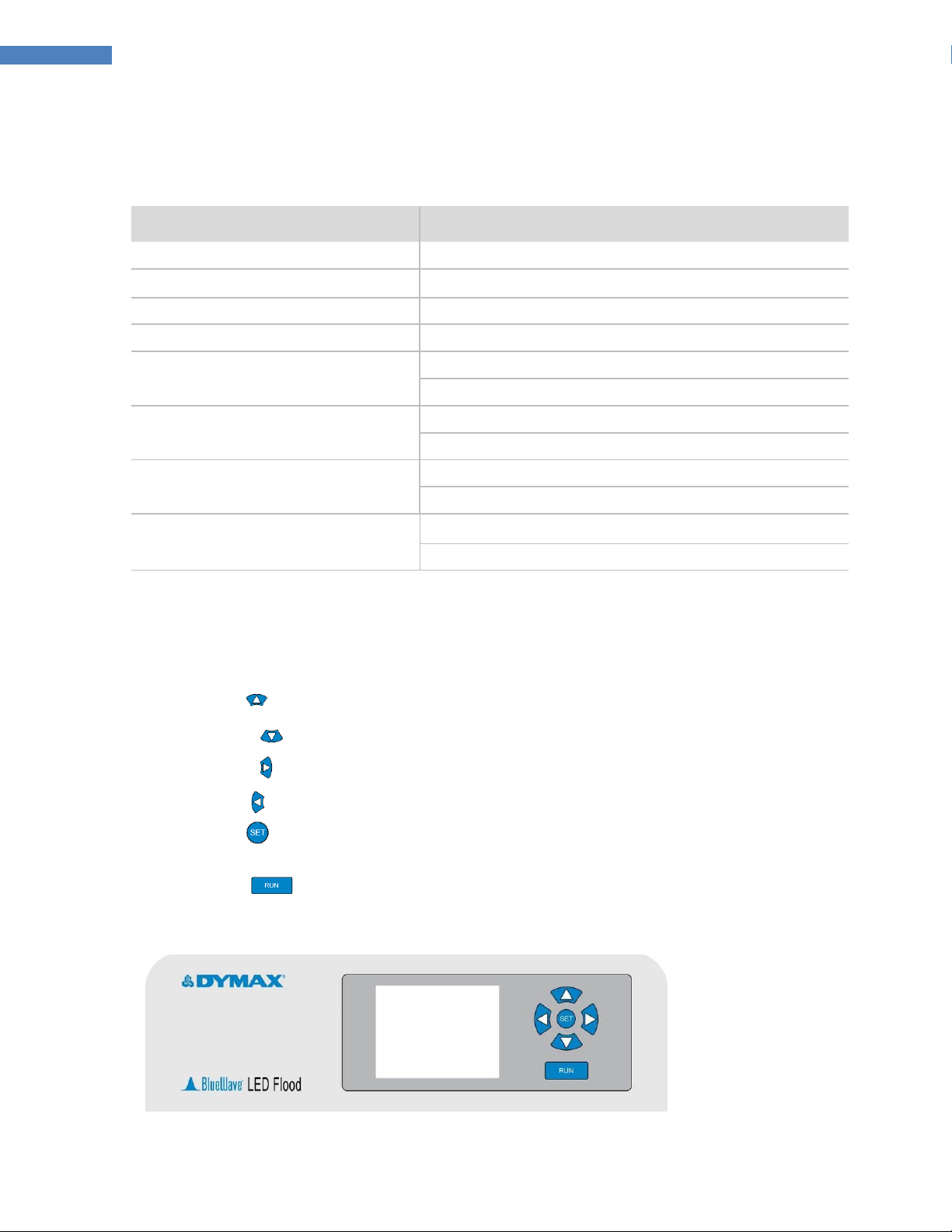
Front Control Panel ....................................................................................................................................................... 10
Back Panel ..................................................................................................................................................................... 11
Intensity Control Feature .............................................................................................................................................. 11
Operation Modes .......................................................................................................................................................... 12
Validation ...................................................................................................................................................................... 12
Assembly and Setup...................................................................................................................................... 12
Safety / Sécurité ............................................................................................................................................................ 12
Unpacking and Inspecting Your Shipment..................................................................................................................... 13
Parts Included in the BlueWave LED Flood System........................................................................................................ 13
System Connections...................................................................................................................................... 14
Interconnect Cable ........................................................................................................................................................ 14
Operating the LED Light ................................................................................................................................ 14
Adjusting Intensity......................................................................................................................................................... 14
Operating Modes........................................................................................................................................................... 15
Choosing an Operating Mode........................................................................................................................................ 16
Operating in Manual Mode........................................................................................................................... 19
Manual Mode Description............................................................................................................................................. 19
Procedure ...................................................................................................................................................................... 19
Operating in Timer Mode.............................................................................................................................. 19
Timer Mode Description................................................................................................................................................ 19
Adjusting the Timer ....................................................................................................................................................... 19
Operating in PLC Mode ................................................................................................................................. 20
PLC Mode Description ................................................................................................................................................... 20
Wiring the PLC Interface................................................................................................................................................ 21
Output Signal Definition ................................................................................................................................................ 23
Troubleshooting the PLC Interface ................................................................................................................................ 24
Testing Fixtures in PLC Mode ........................................................................................................................................ 24
Cleaning and Maintenance ........................................................................................................................... 24
Inspect and Replace Fuses............................................................................................................................................. 24

4
Dymax BlueWave® LED Flood System User Guide
Cleaning the Quartz Optic Plate .................................................................................................................................... 25
Troubleshooting............................................................................................................................................ 25
Spare Parts and Accessories.......................................................................................................................... 28
Spare/Replacement Parts.............................................................................................................................................. 28
Options/Accessories...................................................................................................................................................... 28
Specifications................................................................................................................................................ 29
Specifications................................................................................................................................................................. 29
Index............................................................................................................................................................. 31

5
Dymax BlueWave® LED Flood System User Guide
Introduction
Introduction to the User Guide
This guide describes how to assemble, use, and maintain the Dymax BlueWave® LED Flood System safely and
efficiently.
Intended Audience
Dymax prepared this user guide for experienced process engineers, technicians, and manufacturing personnel.
If you are new to high-intensity LED light-curing systems and do not understand the instructions, contact
Dymax Application Engineering to answer your questions before using the equipment.
Where to Get Help
Dymax Customer Support and Application Engineering teams are available in the United States, Monday
through Friday, from 8:00 a.m. to 5:30 p.m. Eastern Standard Time. You can also email Dymax at
[email protected]. Contact information for additional Dymax locations can be found on the back cover of this
user guide.
Additional resources are available to ensure a trouble-free experience with our products:
Detailed product information on www.dymax.com
Dymax adhesive Product Data Sheets (PDS) on our website
Material Safety Data Sheets (MSDS) provided with shipments of Dymax adhesives
Safety / Sécurité
WARNING! If you use this curing system without first reading and understanding the
information in this user guide, injury can result from exposure to high-intensity light. To reduce
the risk of injury, read and ensure you understand the information in this user guide before
assembling and operating a Dymax BlueWave LED Flood System.
AVERTISSEMENT! Si vous utilisez le système de séchage sans lire le mode d'emploi et
comprendre les informations offertes, des sérieuses blessures peuvent de produire suite à
l'exposition à la lumière de haute intensité. Pour réduire les risques de blessures, veuillez lire et
comprendre les informations du mode d'emploi avant l'assamblage et l'utilisation du système
'Dymax BlueWave LED Flood'.
The BlueWave LED Flood System is not a stand-alone unit and is intended to be incorporated into a larger
system. This integrated system should provide adequate mechanical and electrical safeguards with sufficient
light shielding and protection for safe operator use. Final installation must not block vents. To use a BlueWave
LED Flood System safely, it must be set up and operated in accordance with the instructions given by Dymax.
Using the flood system in any other manner will impair the protection of the system. Dymax assumes no
liability for any changes that may impair the protection of the curing system.

6
Dymax BlueWave® LED Flood System User Guide
Le système 'BlueWave LED Flood' n'est pas un système conçu pour l'utilisation simple, mais pour être
incorporée dans un plus grand système. Ce système intégré doit offrir des mesures de sécurité adéquate pour
le système mécanique et électrique, obstruer totalement la lumière et protéger l'opérateur pour une
utilisation sécuritaire. L'installation finale ne doit pas bloquer les accès pour la ventilation. Pour utiliser en
toute sécurité le système 'BlueWave LED Flood', le système doit être installé et utilisé en suivant les
instructions offertes par Dymax. L'utilisation du système de toute autre façon peut diminuer sa protection.
Dymax n'est pas responsable des changements pouvant diminuer la protection du système de séchage.
General Safety Considerations
All users of Dymax equipment should read and understand this user guide before assembling and using the
equipment.
To learn about the safe handling and use of light-curable formulations, obtain and read the MSDS for each
product. Dymax includes an MSDS with each adhesive sold. In addition, fluid product MSDS can be requested
on the Dymax website.
CAUTION! Always wear protective goggles or face shield when working near UV light. Never
look directly at light!
WARNING! Always observe safety requirements! Do not open the cover of the LED Array or
Power supply. There are no user serviceable parts inside.
PRÉCAUTIONS! Veuillez toujours porter des lunettes protectrices pour les yeux ou pour le
visage lors de travail en contact avec la lumière UV. Ne jamais regarder la lumière directement!
AVERTISSEMENT! Toujours obéir aux exigences de sécurité ! Ne pas ouvrir les couvercles des
lumières LED ou pour l'alimentation électrique. Il n'y a aucune pièce pour l'entretien à l'intérieur.
Safety Recommendations/Recommander de Sécurité
■Use the goggles provided or an approved face shield for eye/face protection.
■Long-sleeved shirts or a lab coat are recommended for arm protection. The use of opaque gloves will protect the
hands.
■Utiliser les lunettes de protection fournies ou une protection pour le visage approuvé pour la protection
des yeux et du visage.
■Il est recommandé d'utiliser un chandail avec des longues manches ou un manteau de laboratoire pour la
protection des bras. L'utilisation de gants opaques protège les mains.
Specific Safety Considerations
The BlueWave LED Flood System is designed to maximize operator safety and minimize exposure to light-
curing energy. To use the unit safely, it must be set up and operated in accordance with the instructions in this
user guide. Please also read and understand the safety considerations unique to LED-curing systems as
described below.

7
Dymax BlueWave® LED Flood System User Guide
WARNINGS! Looking directly at the high-intensity light emitted by the BlueWave Large Area
LED Array can result in eye injury. To prevent eye injury, never look directly at the high-intensity
light and always wear protective goggles (provided).
AVERTISSEMENT! Vous pouvez blesser vos yeux si vous regardez directement la lumière de haute
intensité émise par le système 'BlueWave LED Flood'. Pour la prévention de blessure aux yeux, veuillez ne
jamais regarder directement dans la direction de la lumière de haute intensité et porter des lunettes pour la
protection des yeux (fournies).
Safety Symbol Index
The following symbols are displayed on the curing system. Please see below for their meanings.
Refer to Manual
Warning!
Eye Protection Required
Warning! UV Light Hazard
Electrostatic Sensitive Device
Dymax Light-Curing System Safety Considerations
Operators must understand these three concepts to use the LED light source safely: light exposure, high-
temperature surfaces, and bright, visible light. Each is described below.
Light Exposure
The BlueWave LED Flood System’s PrimeCure™ and RediCure™ models emit energy in the UVA portion of the
spectrum while the VisiCure™model emits energy in the visible portion of the spectrum. UVA light is
generally considered the safest of the three UV ranges: UVA, UVB, and UVC. Although OSHA does not
currently regulate visible or ultraviolet-light exposure in the workplace, the American Conference of
Governmental Industrial Hygienists (ACGIH) does recommend Threshold Limit Values (TLV’s) for ultraviolet
light. The strictest interpretation of the TLV (over the UVA range) for workers’ eyes and skin is 1 mW/cm2
(intensity), continuous exposure. Unless workers are placing bare hands into the curing area, it is unusual to
exceed these limits. To put the 1 mW/cm2limit into perspective, cloudless summer days in Connecticut
regularly exceed 3 mW/cm2of UVA light, which includes the more dangerous UVB light, primarily responsible
for suntans, sunburns, and skin cancer.

8
Dymax BlueWave® LED Flood System User Guide
Figure 1. Light Spectrum
Checking the Workstation
A radiometer should be used to measure stray light to confirm the safety of a light-curing process. A
workstation that continuously exposes an operator to more than 1 mW/cm2of UVA light should be
redesigned.
Protecting Operators
Light-curing technology can be a regulatory compliant, "worker-friendly" manufacturing process when the
proper safety equipment and operator training is utilized. There are two ways to protect operators from
visible light exposure: shield the operator and/or shield the source.
Shield the Operator
Tinted eyewear will shield the operator from high intensity visible energy, and reduce eye fatigue.
Shield the Source of the Light
The BlueWave LED Flood System needs to be used with sufficient light shielding in order to be operated safely.
The LED Flood Array and Power Supply are not designed to be used as a stand-alone unit. Any substrate that
blocks light can be used as a shield to protect workers from stray light. The following materials can be used to
create simple shielding structures:
Sheet Metal –Aluminum, steel, stainless steel, etc. Sheet metal should be coated black or black anodized to
minimize reflection of UV and visible light toward operators.
Rigid Plastic Film –Transparent or translucent/light-blocking plastics (typically polycarbonate or acrylic) are
commonly used to create shielding where some level of transparency is also desired.
Flexible Film –Translucent light-blocking, flexible urethane films can be used to quickly create workstation
shielding. This light-blocking, flexible urethane film is available from Dymax. Call for assistance.
High-Temperature Surfaces
Surfaces exposed to high-intensity curing lights may rise in temperature. The intensity, distance, exposure
time, cooling fans, and composition of the surface can all affect the rise in surface temperature. In some cases,
exposed surfaces can reach temperatures capable of producing a burn or causing damage to a substrate. In
these cases, care must be taken to ensure either a more moderate surface temperature or appropriate

9
Dymax BlueWave® LED Flood System User Guide
protection/training for operators. No infrared radiation is produced by these LED systems, so surface
temperatures will be lower than with conventional lamp systems. Empirical testing should be used to verify
the exact temperature rise in each application.
Bright, Visible Light
The bright, visible light energy emitted by curing systems can cause eye strain if proper eye protection or
shielding is not used. The proper use of tinted eye protection and/or opaque/tinted shielding can be utilized to
reduce eye strain and address this concern.
Product Overview
Description of the BlueWave LED Flood System
The BlueWave LED Flood System is a high-intensity unit used for curing light-curable materials. The unit is
designed to be integrated into a larger system, such as an automated manufacturing system, or with a light
shielding enclosure to create a bench-top curing station.
The BlueWave LED Flood System consists of two main components: an LED flood array and a power supply
that contains the user interface. Dymax offers three different wavelength LED flood arrays: VisiCure® (405
nm), PrimeCure™(385 nm), and RediCure™(365 nm). Only one LED flood array can be connected to the
power supply at a time via the interconnect cable. The power supply is designed to identify the type of LED
array that is connected so the power supply can be used with any of the three LED flood arrays.
The unit can be operated in timed or manual modes and features an intensity adjustment, allowing the output
intensity level to be adjusted from 10 to 100% to meet process and adhesive requirements. LED technology
within the BlueWave LED Flood System allows for instant on/off activation without the need for a warm-up
period, but is also rated for continuous operation.
Fans in the LED flood power supply and array provide cooling and must not be covered or blocked. Fan Filters
must be maintained regularly to ensure reliable operation.
Thermal sensors in the LED flood power supply and array shut the unit down to protect the components if the
internal temperature exceeds maximum limits.
WARNING! If you block the air flow from the LED flood array or the power supply vents,
equipment damage and malfunction can result. To prevent damage and malfunction, ensure 1"
[2.54 cm] of clearance is provided around the power supply and at least 6" [15.24 cm] of clearance
is provided around the cooling fan inlets and outlet to allow the free flow of air.
AVERTISSEMENT! Vous pouvez endommager l'équipement ou avoir des difficultés avec
l'utilisation si vous bloquez la ventilation pour les lumières LED ou l'alimentation électrique. Pour
éviter la détérioration ou le mauvais fonctionnement du système, veuillez vous assurer que
l'installation offre un retrait de 1'' [2.54 cm] autour de l'alimentation électrique et au moins 6''
[15.24 cm] de retrait avec la sortie de ventilation et assurez-vous qu'il y a une bonne circulation
d'air.

10
Dymax BlueWave® LED Flood System User Guide
Special Features and Benefits of the BlueWave LED Flood System
The Dymax BlueWave LED Flood System is engineered for precise performance and long service life.
Key features include:
Feature
Benefit
Curing area up to 5" x 5" [12.7 cm x 12.7 cm]
Large-area cure capability with LED
Flexible mounting options
Adaptable to a variety of process and fixture scenarios
100% duty-cycle capability
Highest throughput (exposure cycles “at the speed of light”)
No mechanical shutter
Instant on/Instant off exposures
Intensity output adjustment by keypad or PLC
(10 to 100%)
Superior accuracy over “closed loop feedback" or auto-adjusting units
Optimum process control
Co-optimized to cure with Dymax formulations
Compatibility with many formulations
Fewer re-qualifications
Stable LED temperature
Optimizes cure time efficiency
Increases LED life
LED
Superior LED cooling for consistent frequency output
Longer LED life via reduced intensity degradation
Front Control Panel
The LED flood system has a simple, easy-to-use front interface. The front control panel is located on the right
side of the power supply and is used to make all manual adjustments.
■Up Button ( ) - Navigates the selector up one position.
■Down Button ( ) - Navigates the selector down one position.
■Right Button ( ) - Navigates the selector right one position.
■Left Button ( ) - Navigates the selector left one position.
■Set Button ( ) - Located in the center of the arrow buttons. This button selects the option highlighted
on the screen
■Run Button ( ) - This button is used to activate the LED flood array when in manual mode.
Figure 2. Front Control Panel

11
Dymax BlueWave® LED Flood System User Guide
Back Panel
The back panel includes these components and connection points:
■Power Cord Receptacle —Connection point for the power cord.
■I/O (On/Off) Switch —Moving the switch to the I (on) position powers up the power supply. Moving the
switch to the O (off) position cuts power to the power supply.
■Cooling Air Exhaust —Cooling air enters the side vents and exhausts out the rear of the unit.
NOTE: The exhaust vents on the rear of the power supply must not be blocked or the unit may overheat
and shut down. Ensure 1" [2.54 cm] of clearance is provided around the power supply and at least 6"
[15.24 cm] of clearance is provided around the cooling fan inlets and outlet.
■Foot-Switch Jack —Connection point for the foot switch. Pressing the foot switch starts a curing cycle.
In timed operation, pressing and releasing the foot switch activates the curing array for the length of time
displayed in the cycle time display. A second press will terminate a timed cure cycle immediately. In
manual operation, pressing and holding the foot switch activates the curing light until the foot switch is
released.
■PLC Access Switch –Button used to temporarily unlock the option to access PLC mode.
■PLC Connector —Connection point for a user-supplied cable to connect the unit to a PLC for remote
operation. Connection is a standard 25-pin D-style connector. Refer to page 19 for details on the
connections to this port.
■Array Cable Connector —Connection point for the interconnection cable connecting the power supply
to the array.
Figure 3. Back Panel
Intensity Control Feature
The components used in all light-curing systems degrade with use. Therefore, the maximum intensity
decreases as exposure hours accumulate. Setting process intensity requirements lower than the maximum
enables the BlueWave LED Flood’s intensity control feature to allow for compensation of gradual decreases in
light intensity.
The unit's intensity can be adjusted using the intensity adjustment on the front control panel as a percentage
of full scale intensity.

12
Dymax BlueWave® LED Flood System User Guide
Use a radiometer to correlate the power output setting to a reading in W/cm2. The adjustment of power level
and correlation to an intensity value (W/cm2) enables precise control of light intensity during validation and
operation.
Operation Modes
The power supply allows the user to select between manual activation mode, timer mode, or PLC mode. The
manual mode allows the user to active the LED array via a foot switch or by pressing the run button. The timer
mode allows the user to activate the LED array for a set amount of time. PLC mode allows an external
machine to control all functions of the unit.
Validation
Tests should be conducted prior to production to determine the time and light intensity required to fully cure
your resin. The following approaches may be used to validate the curing process.
Set Exposure Time, Determine Intensity
Users can specify a cure time and, through empirical testing, determine the intensity required to achieve a full
cure. As with any manufacturing process, it is advisable to incorporate a safety factor.
Set Intensity, Determine Exposure Time
Users can specify light intensity and, through empirical testing, determine the exposure time required to
achieve a full cure. As with any manufacturing process, it is advisable to incorporate a safety factor.
Control
Process validation confirms a minimum acceptable intensity. Users can then choose to operate at full intensity
(using the excess intensity as an additional safety factor) or adjust the output to a specific intensity level. To
ensure consistent and repeatable process results, intensity levels should be monitored with a radiometer. This
enables users to identify changes in light intensity and take corrective action: either adjusting the light
intensity or performing maintenance.
Assembly and Setup
Safety / Sécurité
The BlueWave LED Flood System is not a stand-alone unit and is intended to be incorporated into a larger
system. This integrated system should provide adequate mechanical and electrical safeguards with sufficient
light shielding and protection for safe operator use. Final installation must not block vents. To use a BlueWave
LED Flood System safely, it must be set up and operated in accordance with the instructions given by Dymax.
Using the flood system in any other manner will impair the protection of the system. Dymax assumes no
liability for any changes that may impair the protection of the curing system.
Le système 'BlueWave LED Flood' n'est pas un système conçu pour l'utilisation simple, mais pour être
incorporée dans un plus grand système. Ce système intégré doit offrir des mesures de sécurité adéquate pour

13
Dymax BlueWave® LED Flood System User Guide
le système mécanique et électrique, obstruer totalement la lumière et protéger l'opérateur pour une
utilisation sécuritaire. L'installation finale ne doit pas bloquer les accès pour la ventilation. Pour utiliser en
toute sécurité le système 'BlueWave LED Flood', le système doit être installé et utilisé en suivant les
instructions offertes par Dymax. L'utilisation du système de toute autre façon peut diminuer sa protection.
Dymax n'est pas responsable des changements pouvant diminuer la protection du système de séchage.
Unpacking and Inspecting Your Shipment
When your BlueWave LED Flood System arrives, inspect any boxes for damage and notify the shipper of box
damage immediately.
Open each box and check for equipment damage. If parts are damaged, notify the shipper and submit a claim
for the damaged parts. Contact Dymax so that new parts can be shipped to you immediately.
Check that the parts included in your order match those listed below. If parts are missing, contact your local
Dymax representative or Dymax Customer Support to resolve the problem.
Parts Included in the BlueWave LED Flood System
■LED Flood Power Supply (1) –PN 41276
■LED Flood Array (2) –VisiCure® (PN 41211), PrimeCure™ (PN 41210), or RediCure™ (PN 41212) model
■Power Cord (3) –Dependent on model ordered. Available options listed below:
oStandard North American Power Cord (PN 41274)
oType G Power Cord for Asia (PN 41275)
oNo Power Cord (Note: For European customers, the appropriate power cord will be added)
■Foot Switch (4) –PN 5028
■Safety Glasses (5) –PN 35285
■Interconnect Cable (6) –PN 41228 –Connects the power supply to the array
■BlueWave LED Flood System User Guide (7) –PN 41264
Figure 4. BlueWave LED Flood System Components
(2) LED Flood Array
(5) Safety Glasses
(1) LED Flood Power Supply
(3) Power Cord
(7)User Guide
(6) Interconnect Cable
(4) Foot Switch

14
Dymax BlueWave® LED Flood System User Guide
System Connections
WARNING! Make sure the unit is turned off and unplugged before you make any connections
to the back panel. Never attempt to unplug or attach a cable when the unit is turned on.
AVERTISSEMENT! Assurez-vous que l'unité est hors tension et débranché avant d'effectuer
une connexion sur le panneau électrique (derrière l'unité). Ne jamais débrancher ou attacher un
câble lorsque l'unité est alimentée.
NOTE: The unit should be positioned so that the back panel of the power supply can easily be
accessed should the power need to be disconnected.
Interconnect Cable
The interconnect cable runs from the back panel of the power supply to the top of the LED flood array.
Figure 5. Connect Interconnect Cable to
Power Supply
Figure 6. Connect Opposite End of
Interconnect Cable to LED Flood Array
Operating the LED Light
Adjusting Intensity
The output intensity can be adjusted from 10% (depending on the LED Flood configuration ordered) to 100%
in 1% increments. To adjust the intensity:
1. From the main screen, press and hold the button on the front control panel for several seconds until
the Options Menu (Figure 7) appears.
2. Use the and the so that the “Adjust Intensity” option is flashing and press the button to enter
the Adjust Intensity Menu (Figure 8).
3. Use the , , , or keys to adjust the intensity setting. Press the Set button to enter
the value and exit to the main page.

15
Dymax BlueWave® LED Flood System User Guide
NOTE: If you enter intensity that is too low for the LED Flood Array attached the unit, the unit will beep for 5
seconds, and the intensity will not change.
If you are operating in PLC mode, a PLC input signal allows intensity to be selected from this menu or allows
intensity to be controlled directly by the PLC.
Figure 7. Options Menu
Figure 8. Adjust Intensity Menu
Operating Modes
There are three basic operating modes: Manual Mode, Timer Mode, and PLC Mode.
Manual Mode: The LED activates whenever the foot switch or the run button on the front panel is pressed.
The LED remains active only as long as the foot switch or run button is pressed. When the foot switch and run
button are released, the LED shuts off.
NOTE: PLC outputs are always active in manual and timer mode.
Timer Mode: The LED is active for a specific time period each time the foot switch or run button is pressed.
You must set the specific time by adjusting the timer’s value on the screen. Momentarily pressing the foot
switch or run button starts the timer and activates the LED. Once the timer counts down to zero, the shutter
closes, and the timer resets to the value that you set and is ready for another exposure cycle. The activation
can be cancelled at any time during the exposure cycle by pressing the foot switch or run button.
NOTE: PLC outputs are always active in timer and manual mode.
PLC Mode: An external PLC (Programmable Logic Controller) controls the unit. The PLC provides input signals
to the BlueWave LED Flood to control the LED. The PLC monitors the status of the unit by reading output
signals provided by the BlueWave LED Flood. The PLC is typically programmed to start other machinery when
the unit becomes ready, or perhaps start the unit when other machinery is ready. The input signals and
output signals are present through the 25-pin connector on the power supply’s back panel marked PLC.
NOTE: The run button can be used to activate the LED light without PLC commands to assist fixture
troubleshooting.

16
Dymax BlueWave® LED Flood System User Guide
Choosing an Operating Mode
NOTE: Upon power-up, your BlueWave LED Flood System will default to its last configuration settings.
Figure 9. Mode Start-up Screens (Left to Right: Manual Mode, Timer Mode, PLC Mode)
NOTE: If the BlueWave LED Flood System powers up in PLC Mode,you cannot change any settings via the front
panel controls until you press the PLC Access Switch on the back panel.
To Switch Between Manual and Timer Mode:
1. From the main page, press the button to open the Options Menu (Figure 10).
2. Use the and buttons, so that the “SELECT MODE” option is flashing and press the button to
open the Select Mode Menu (Figure 11).
3. Using the and buttons, highlight the desired mode and press the button.
4. The mode has now been set and the screen should return to the main page.
Figure 10. Options Menu
Figure 11. Select Mode Menu

17
Dymax BlueWave® LED Flood System User Guide
Selecting the PLC Mode from the Timer or Manual Mode:
1. Press the PLC Access Switch on the back of the unit (Figure 12).
2. From the main page, press the button to open the Options Menu (Figure 13) within 30 seconds.
Figure 12. PLC Access Switch
Figure 13. Options Menu
3. Use the and buttons, so that the “SELECT MODE” option is flashing and press the button
to open the Select Mode Menu (Figure 14).
4. Using the and buttons, highlight “PLC MODE” and press the button.
NOTE: If you do not see “PLC Mode”, then select “CANCEL” using the and buttons and press
the button. Then follow the instructions starting at step 1.
5. PLC Mode selection is successful if the screen below appears.
Figure 14. Select Mode Menu
Figure 15. PLC Mode Menu

18
Dymax BlueWave® LED Flood System User Guide
Selecting Timer or Manual Modes from the PLC Mode:
1. Press the PLC Access Switch on the back of the unit (Figure 16).
NOTE: The padlock will disappear from the PLC Mode screen after you press the PLC Access Switch.
2. Press the button. The Options Menu should appear (Figure 17).
NOTE: If the screens do not change after you press the button, then go back to step 1.
Figure 16. PLC Access Switch
Figure 17. Options Menu
3. Use the and buttons, so that the “SELECT MODE” option is flashing and press the button
to open the Select Mode Menu (Figure 18).
4. Using the and buttons, highlight “TIMER MODE”or “MANUAL MODE” and press the
button.
Figure 18. Select Mode Menu

19
Dymax BlueWave® LED Flood System User Guide
Operating in Manual Mode
Manual Mode Description
Manual Mode means that the LED activates whenever the foot switch or the run button on the front panel is
pressed. The LED remains active only as long as the foot switch or run button is pressed. When the foot pedal
and run button are released, the LED shuts off.
Procedure
1. Ensure the BlueWave LED Flood is in Manual Mode
(Figure 19). If the system is not in Manual Mode, follow
the instructions in “Choosing an Operating Mode”.
2. Verify that the LED Head is connected properly to the
Power supply via the Interconnect Cable.
3. Press and hold the Footswitch or the Button on
the front panel to activate the LED.
4. To stop exposure, release the Footswitch or the
Button on the front panel.
NOTE: The “LED ON” text will only appear when the
footswitch or run button is pressed.
Operating in Timer Mode
Timer Mode Description
Timer Mode means that the LED is active for a specific time period each time the foot switch or run button is
pressed. You must set the specific time by adjusting the timer’s value on the screen. Momentarily pressing
the foot switch or run button starts the timer and activates the LED. When the timer counts down to zero, the
shutter closes, and the timer resets to the value that you set and is ready for another exposure cycle. The
activation can be cancelled at any time during the exposure cycle by pressing the foot switch or run button.
NOTE: A timed exposure can be interrupted with the foot switch or the button on the front panel.
Adjusting the Timer
1. Ensure the BlueWave LED Flood is in Timer Mode (Figure 20). If the BlueWave LED Flood is not in Timer
Mode, follow the instructions in “Choosing an Operating Mode”.
2. If the time on the screen is correct, skip to Step 6. Otherwise you need to adjust the Timer to the correct
value by following the next steps.
Figure 19. Manual Mode -
Activated Screen

20
Dymax BlueWave® LED Flood System User Guide
3. Press and release the Button to enter the Options Menu (Figure 21).
4. Use or Arrows so that “ADJUST TIMER” is flashing and press the Button.
5. The Adjust Timer Screen (Figure 22) will display. Use the Directional Keys to adjust the Timer to the
correct value. The Timer can be adjusted from 0000.0 seconds to 9999.9 seconds. Press and release the
Button when you have entered the desired activation time.
Figure 20. Time Mode
Main Screen
Figure 21. Options Menu
Figure 22. Adjust Timer
Screen
6. Press the Foot Switch or the Button on the front panel to start the Timer. An exposure cycle can
be cancelled at any time by momentarily pressing the Button or Foot Switch.
Operating in PLC Mode
PLC Mode Description
CAUTION! Always wear protective goggles or a face shield when working near UV light. The
PLC is capable of turning on the LED at any time, or when a user selects PLC Mode from the front
panel controls.
PRÉCAUTIONS! Veuillez toujours porter des lunettes protectrices pour les yeux ou pour le
visage lors de travail en contact avec la lumière UV. Le 'PLC' peut mettre sous tension le système
DEL en tout temps, ou lorsque l'utilisateur sélectionne le mode 'PLC' avec les commandes du
panneau frontal.
PLC Mode means that an external PLC (Programmable Logic Controller) controls the system. The PLC provides
input signals to the flood unit to control the LED. The PLC monitors the status of the flood unit by reading
output signals provided by the unit. The PLC is typically programmed to start other machinery when the flood
unit becomes ready, or perhaps start the flood unit when other machinery is ready. The input signals and
output signals are present on a connector on the back of the power supply labeled ‘PLC’.
NOTE: Output signals are always provided in manual mode and timer mode to allow simple interfacing to
alarms, counters, other interlocks, etc. even if a PLC will not be controlling the unit. However, the input signals
will be ignored in manual mode and timer mode.
This manual suits for next models
11
Table of contents
Other dymax Laboratory Equipment manuals
Popular Laboratory Equipment manuals by other brands

Velp Scientifica
Velp Scientifica AREX-6 instruction manual

MELAG
MELAG MELAquick 12+ p user manual

EXFO
EXFO FLS-2800 user guide

Thermo Scientific
Thermo Scientific Orbitrap Fusion Lumos MS Getting connected guide

Nippon
Nippon WA-5A Service manual

Agilent Technologies
Agilent Technologies 7890A quick reference