Dyna-Form Mercury Advance User manual

User Manual
DIRECTHEALTHCARESERVICES.CO.UK

DIRECTHEALTHCARESERVICES.CO.UK
2
DYNA-FORM MERCURY ADVANCE

DIRECTHEALTHCARESERVICES.CO.UK
USER MANUAL
3
The Dyna-Form Mercury Advance is a pressure relieving mattress suitable for use with patients at VERY HIGH RISK
of pressure ulcer damage.
Offering high levels of patient comfort, this unique system has the facility to “step up” to that of a dynamic mattress when clinically
required. Similarly, the mattress’s function can be downgraded as the patient’s condition improves.
These features make it particularly beneficial for use within the patient’s home or palliative care environment and help reduce
logistic and decontamination costs. The clinical benefits of a single system are equally applicable to those of a modern hospital
setting. A higher maximum weight capacity, up to 40 stone / 254kg, allows the product to meet the modern challenges of
those heavier clients. All component parts are interchangeable and replaceable, maximising product life and reducing
environmental impact.
1. Introduction .....................................................................................................................................................................4
2. Quick Reference Guide & Frequently Used Functions............................................................................................................4
3. Troubleshooting ...............................................................................................................................................................6
4. Installation .......................................................................................................................................................................7
5. Operation .........................................................................................................................................................................7
6. Transportation ..................................................................................................................................................................8
7. Warnings .........................................................................................................................................................................8
8. Maintenance Procedures...................................................................................................................................................9
9. Technical Data ...............................................................................................................................................................10
10. Optimum Conditions for Use ..........................................................................................................................................10
11. Symbols Guide & Contraindications for Use .....................................................................................................................10
12. Detachable / Removable Parts .......................................................................................................................................11
13. Disposal ......................................................................................................................................................................11
Contents

DIRECTHEALTHCARESERVICES.CO.UK
4
DYNA-FORM MERCURY ADVANCE
1. Introduction
The Mattress consists of a foam head cell and series of 14 transverse air cells, each containing a unique
foam profiled insert, which are in turn held within a foam U Core, all protected by a vapour permeable
waterproof cover. The single head end cell and the formers consist of foam only. The transverse cells are
arranged into alternate pairs of A and B cells which are filled and emptied in sequence.
In Static Mode, the mattress attains the pressure reducing properties of the Dyna-Form Mercury
static foam mattress (details available on request), whilst in Alternating Mode the mattress is able to
offer similar properties to a pressure relieving dynamic system.
The digital Control Unit controls a Control Unit that allows air to flow into, or out of the air cells as
required according to the operating mode selected. It also maintains the air pressure within the
mattress at the required level and controls the action of the audible/visual Audible Warning system
in the event of mains supply failure or over or under inflation pressure. A CPR Valve located at the
Control Unit end of the umbilical hose permits the rapid deflation of the Mattress in an emergency.
Power Switch Audible Warning Reset
The power switch simply switches the mains power to the Control Unit on and off.
When the Control Unit detects an Audible Warning condition, this can be silenced (see page 5)
and re-set by switching the Control Unit off and then back on again.
CPR Valve
Please ensure that the CPR connector is always placed fully home, prior to inflating the mattress.
NB: The mattress will NOT inflate properly should this not be the case.
The CPR connector is only to be used in the event of a clinical emergency for priority use.
However, disconnecting this function will cleverly deflate air rapidly from the mattress in
readiness for transport / static mode.
2. Quick Reference Guide (Frequently used functions)
This is a quick reference guide for the Dyna-Form Mercury Advance System
Product Code MAT1210001

DIRECTHEALTHCARESERVICES.CO.UK
USER MANUAL
5
This symbol when illuminated (The green indicator light) is used to indicate that the equipment is
on or ready for use.
When a patient requires a true dynamic function or indeed more pressure in the cells, as they
may be uncomfortable or feel as though the support surface is too soft or unstable, then please
select a “High” setting (pressure 26mmHg). This must only be used by a trained clinician as often
too high pressures can further agitate certain patient conditions.
When a patient requires less pressure in the cells, as they may be uncomfortable or indeed hyper
sensitive to cell movement or indeed if the patient is still reddening further, then please select a
“Low” setting (pressure 18mmHg). This must only be used by a trained clinician.
This function is used to silence the Audible Warning. The LED will remain lit if the Audible
Warning has been silenced previously, however a fault is still detected. Refer to the power switch
in order to re-set fully. If the Audible Warning continues to sound repeatedly, along with an
illuminated light, then an engineer must be called.
This symbol indicates an “Audible Warning Failure”.
Please see troubleshooting guide below for how to re-set.
This symbol when illuminated indicates a Service is required.
DHS recommends a service every 8760 hours of operation (one continuous year running).
LED Mode Settings
Note: Please ensure (when available) that all securing straps on the base of the mattress are secured onto
the MOVING PARTS of the bed frame.
For shut down procedure, see 4.2 Control Unit section.
Power On / Off
True Dynamic /Firmer Setting
Silence Audible Warning
Audible Warning Failure
Service Indicator
Low / Comfort Pressure Setting

DIRECTHEALTHCARESERVICES.CO.UK
6
DYNA-FORM MERCURY ADVANCE
Warning / Fault Cause
Control Unit does
not operate;
no display lights
illuminate
The Control
Unit may not be
attached to a
power source or
a fuse may need
replacing.
1. Check the Control Unit is connected to mains power outlet with the correct voltage.
2. Check the Control Unit is switched on. Switch off and unplug the unit before restarting.
3. Check the mains plug fuse (5 AMP) then check both Control Unit fuses (1 AMP) –
fuses can be released using a screwdriver to push and turn.
Do not try to open the Control Unit. Opening the unit could cause personal injury
or equipment damage.
Ensure the replacement of fuses is carried out accordance with local legislation.
Warning LED C
+ Audible Warning
Mains failure /
Other
See above,
plus:
1. Check the Control Unit is connected to mains power outlet with the correct voltage.
2. Check the Control Unit is switched on. Switch off and unplug the unit before restarting.
3. Check the mains plug fuse (5 AMP) then check both Control Unit fuses (1 AMP) – fuses can be
released using a screwdriver to push and turn.
Do not try to open the Control Unit. Opening the unit could cause personal injury or equipment
damage.
Ensure the replacement of fuses is carried out accordance with local legislation.
Warning LED B
+ Audible Warning
Pressure too low 1. Reset the warning – turn off power and press the Audible Warning mute button.
2. Check that the CPR connector is firmly attached to the Control Unit (located on the left of the
Control Unit case) Check all air hoses along the inside of the mattress – each should be firmly
connected. Check each air cell is securely attached to its connecting air pipe.
3. Check all cells, pipes and hoses for any air leakage.
4. Check that the air filter cover is correctly secured and the air filter is clean.
5. Switch on power.
Warning LED B+C
+ Audible Warning
Pressure too low /
Air pipe kinked
1. Check Blue external umbilical air pipe that is between mattress and CPR connector is not
kinked. twisted or damaged.
2. Check all air hoses along the inside of the mattress – each should be firmly connected.
3. Check each air cell is securely attached to its connecting air pipe.
Warning LED A
+ Audible Warning
Pressure
too high
1. Reset the warning – turn off power and press the Audible Warning button.
2. Disconnect the air hoses to reduce pressure, reconnect when pressure has decreased.
3. Check for twists in the air hoses between Mattress and Control Unit.
Warning LED A+B
+ Audible Warning
Alternating
Mode Failure (no
alternation)
1. Reset the warning – turn off Power and press the Audible Warning mute button.
2. Disconnect the air hoses to reduce pressure – reconnect when pressure has decreased.
Warning LED A,B+C
+ Audible Warning
Initialising Failure 1. Press the Audible Warning mute button to silence the Audible Warning.
2. Check all air hoses along the inside of the mattress – each should be firmly connected.
Check each air cell is securely attached to its connecting air pipe.
3. Check that the CPR connector is firmly attached to the Control Unit
(located on left of control unit casing).
Solution
3. Troubleshooting

DIRECTHEALTHCARESERVICES.CO.UK
USER MANUAL
7
4. Installation
4.1 Mattress (This is the applied part type BF)
Place the Dyna-Form Mercury Advance Mattress directly on to the bed platform ensuring that the
Blue multi-stretch waterproof cover is on top and that the umbilical hose is located at the left-
hand corner at the foot end of the bed. Note: The umbilical hose can be located inside the cover
under the “Open Here for Air Inlet” printed in the bottom left hand corner of the mattress.
Cover the Mattress with a loose-fitting sheet.
Static Mattress Use
The Dyna-Form Mercury Advance Mattress can be used as a pressure reducing mattress for
patients at High Risk of pressure ulcer damage without the need to attach the Control Unit.
Alternating Mattress Use
If / When required, the Dyna-Form Mercury Advance Mattress can be used as an alternating
mattress system by attaching the Dyna-Form Mercury Advance Control Unit system.
No other system should be attached to the mattress as the design settings and internal air
pressure properties of the Dyna-Form Mercury Advance Control Unit) are specific to this
mattress only.
The Dyna-Form® Mercury Advance is a replacement mattress system and should NOT be placed
on top of any existing mattress.
The startup time from static to dynamic mode is immediate.
4.2 Control Unit
Hang the Control Unit onto the footboard. The mounting hooks swivel to suit the thickness of the
footboard or rail. Connecting the Umbilical Hose to the Control Unit , place the supplied 3-pin
electrical plug into the wall outlet and switch on:
(a) Open the zip located at the bottom left hand side of the mattress and pull out the Blue Umbilical hose.
(b) Attach the Blue Umbilical Hose to the Control Unit by connecting the air connector at the end of
the Umbilical Hose to the air inlet connector at the bottom left hand side of the
Control Unit. Ensure that the Red CPR Release button is located on top of the Air Inlet connector
after connection is complete.
(c) Re-close the zip as far as possible without clamping the Blue Umbilical Hose to ensure the
mattress and air cells are sealed within the cover.
(d) Shut down is the reverse of items a, b & c above.
5. Operation
Attach the supplied mains cable to the Control Unit by inserting the “kettle” type connector into
the recess located on the left-hand side of the Control Unit. The mains cable has been designed
specifically as a removable part to aid in easy replacement should it become damaged in use.
Power cables not supplied by Direct Healthcare Services are not recommended for use with this
Control Unit.
The mains plug should be turned off and removed from wall socket as a means of isolation.
Plug the mains cable into a suitable 230v mains socket and switch on the Control Unit using the
on/off switch.
After the Control Unit has been turned on both the “High “and the “Low” lights will flash together
intermittently until the Control Unit has attained its initial operating pressure. Once the Control Unit
has attained its initial operating pressure the “Low” light will stay on constantly and the mattress is
ready for use.

DIRECTHEALTHCARESERVICES.CO.UK
8
DYNA-FORM MERCURY ADVANCE
5.1 Low / High Settings
The Dyna-Form Mercury Advance Mattress, in Alternating Mode, has two pressure settings. The
initial setting that the control unit will revert to upon set up is “Low”. The “Low” comfort setting
is ideal for the lighter patient or those who feel discomfort when on a normal alternating air type
mattresses system. However, for patients with existing pressure damage or those at Very High
Risk, it is recommended that dependant on the clinical judgement of the clinician,
the “High” setting is activated by pressing the +/- button once, which is located on top of the
Control Unit.
In “High” Mode the Control Unit attains more of the characteristics of an alternating air mattress
system whilst still utilising the advantages of the static foam inserts. Repeatedly pressing the
‘mode’ button enables the Low & High modes to be selected in turn.
5.2 CPR Deflation
The CPR system consists of a manually operated button located on the Air Inlet connector
attached to the Control Unit. By pressing the Red Button, which will release the connector locking
system, the user can remove the connector unit which will deflate the mattress air system back to
that of a static foam mattress.
Note: After a short period as the Mattress deflates the ‘Low Pressure’ Audible Warning is
activated and can be cancelled by switching the Control Unit off.
5.3 Troubleshooting
For assistance (if needed) in setting up, using or maintaining the Mercury Advance System, or to
report unexpected operation or events, please contact Direct Healthcare Services on the contact
details on the reverse of this manual.
6. Transportation
To change the location of the mattress, remove the Umbilical Cord and allow the mattress
to return to its Static Mattress form. Switch off the Control Unit using the on/off switch and
disconnect the electrical supply cable from the mains socket. The mattress can now be moved
to a new location where it must immediately be reconnected to the mains electrical supply and
the Control Unit switched back on. Once the Mattress has been refilled, the ‘Alternating’ mode
will automatically revert back to the Low setting and should be reselected to High should this be
desired by the clinician.
Warning: The Mattress will not ‘alternate’ when disconnected from Control Unit and /or the mains
electrical. Also, refer to environmental conditions section at rear of this manual.
7. Warnings
Warning conditions are indicated by a flashing red display accompanied by an Audible Warning.
In each case the user should respond by turning the Control Unit’s switch off and investigating the cause.
7.1 High Pressure Warning
This condition could be caused, for example by a kinked Umbilical Hose or visitors,
and others, sitting suddenly on the Mattress.
7.2 Low Pressure Warning
This condition could be caused, for example, by incorrect fitting of the air inlet connector,
opening of the CPR Valve or a leak in the Mattress due to a cut or puncture.
7.3 Mains Failure Warning
This condition may be caused, for example if Mains power is lost.

DIRECTHEALTHCARESERVICES.CO.UK
USER MANUAL
9
8. Maintenance Procedures
8.1 Safety Warning
Only qualified technicians trained or formally approved by Direct
Healthcare Services Ltd. in the operation and maintenance of
Direct Healthcare Services products may carry out maintenance,
modification or repair work on the equipment. Unqualified
personnel attempting to work on Direct Healthcare Services
Control Units risk serious injury to themselves and others and
possibly death by electrocution. Inlet fuse NOT to be replaced by
operator or patient, to be replaced by service personnel only.
Warning – Do not modify this equipment without
authorisation of Direct Healthcare Services.
8.1.1 Servicing
A service light will illuminate when a service is due.
Direct Healthcare Services (DHS) recommend that the Control
Unit should be serviced every 8760 hours of operation (one
continuous year running). The unit contains no user serviceable
parts and should only be carried out by persons as described
in section 8.1. DHS will make available on request all manuals,
component parts lists and other information necessary for any
suitably qualified person (As in 8.1) to carry out repair or service the
system. For Service, maintenance and any questions regarding this
please contact DHS.
8.2 Cleaning Procedures
Warning: Before cleaning the System make sure that the Control
Unit is disconnected from the mains electricity supply.
Do not immerse the Control Unit in water or other fluids.
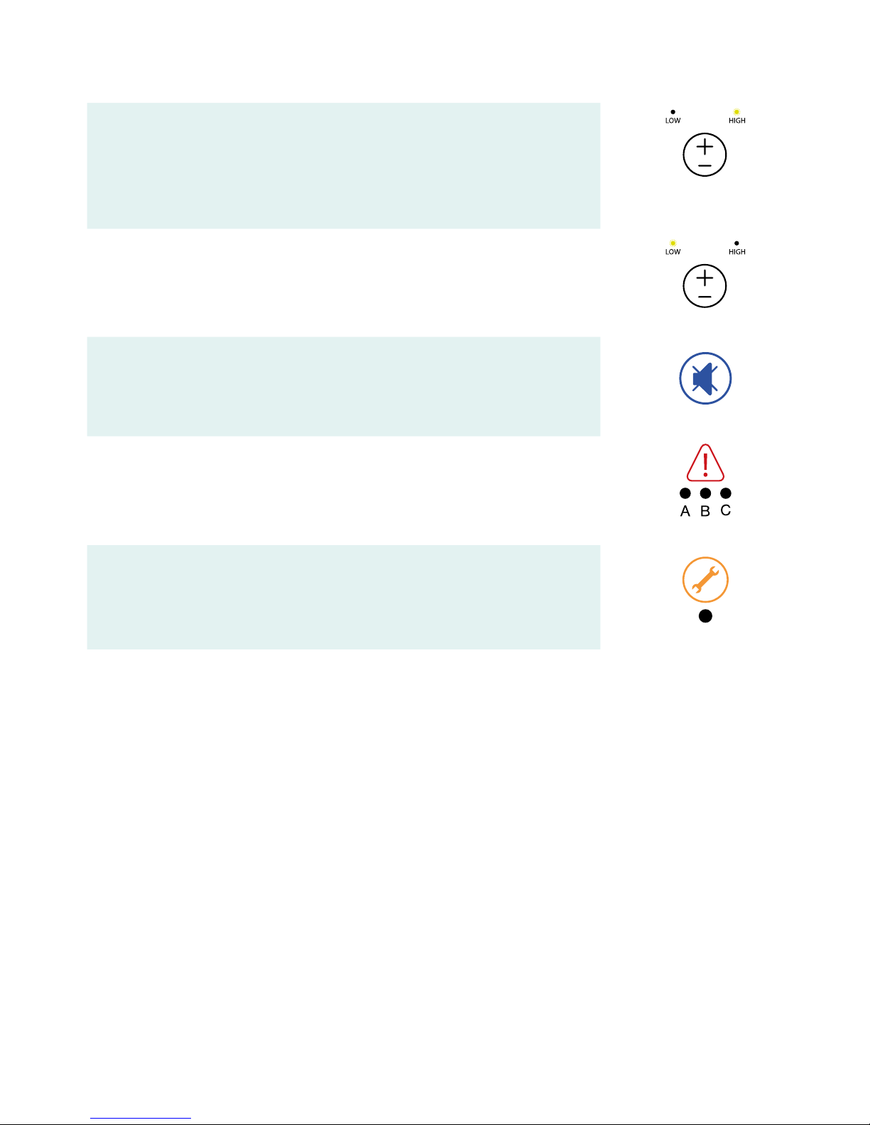
Do not autoclave, nor use phenol for cleaning.
Do wash hands before commencing the cleaning process.
Wear appropriate protective clothing such as gloves, apron
and a mask.
Ensure all work surfaces are cleaned before and after contact
with the Mattress.
8.3 Warning – Cleaning the Mattress
1. Cleaning should take place after use or between patients.
2. With cover left on the Mattress disconnect the Mattress from
the Control Unit.
3. Clean the surface of the wash down table with Hypochlorite
solution or equivalent disinfectant.
4. Wash Mattress top using hot water (60 degrees C) containing
detergent – dry with a paper towel.
5. Use a Hypochlorite solution 1,000 parts per million available
chlorine. For heavy contamination use a Hypochlorite solution
10,000 parts per million available chlorine.
Please ensure
thorough rinsing after cleaning.
6. Using suitable brush, hot water, detergent or Hypochlorite
solution, clean Umbilical Hose and CPR Valve. Dry with
paper towel.
7. If required, the Mattress Cover may be removed and
machine-washed at a temperature of 80 degrees C, for not
less than 10 minutes. The individual Air Cells can be wiped
down with established disinfectants.
8. To avoid shrinkage of the coverline dry in an indoor clean
environment or tumble dry on a low heat setting not
exceeding 40 degrees C and not for longer than 10 minutes.
Covers must be thoroughly dried before re-fitting to the
mattress.
8.4 Warning – Cleaning the Control Unit
The Control Unit can be cleaned by wiping with a cloth
dampened with a detergent solution or Hypochlorite solution.
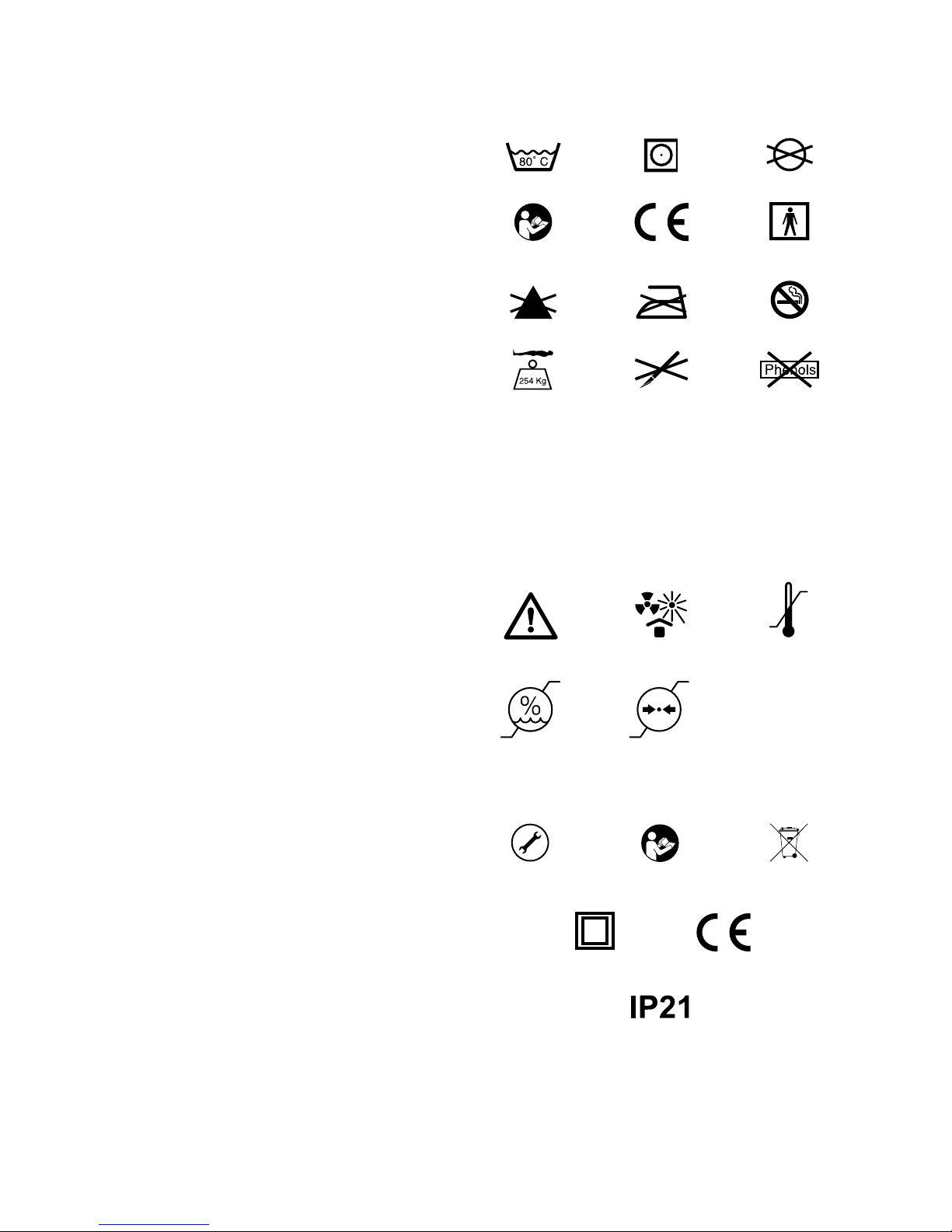
Also, refer to symbol chart.
8.4.1 Warning
Ensure the Mercury Advance System is not exposed to:
1. Excessive heat sources e.g. fires, radiators etc.
2. Water, particularly immersion of the Control Unit.
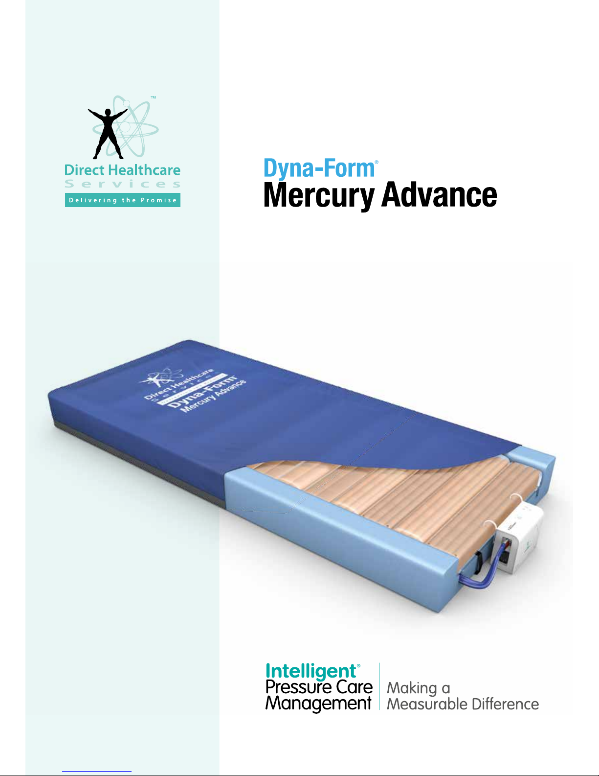
7.4 Alternating Mode Failure (no alternation)
This will be indicated by a warning LED on A and B and an Audible Warning.
1. Reset the warning – turn off Power and press the Audible Warning mute button.
2. Disconnect the air hoses to reduce pressure – reconnect when pressure has decreased.
7.5 Initialising Failure
This will be indicated by a warning LED on A, B and C and an Audible Warning.
1. Press the Audible Warning mute button to silence the Audible Warning.
2. Check the power cable is firmly plugged into the mains outlet and the Control Unit;
and check the mains power is switched on.
3. Check the Control Unit fuse (1 AMP) – fuses can be released using a screwdriver
to push and turn.

DIRECTHEALTHCARESERVICES.CO.UK
10
DYNA-FORM MERCURY ADVANCE
9. Technical Data
9.1 Control Unit
Serial Number ................... As per label on rear of Control Unit
Electrical Supply. .............................. 220 – 240 volts, 50 Hz
Power Consumption ...............................................10 watts
Fuses ................................................................TA1H 250V
Protection against shock ...........................................Class 2
Noise Level ...............................................Approx. 30 dB (A)
Dimensions ...........................................245 x 160 x 95 mm
Weight...................................................................... 1.7 kg
Service Interval ............................... 12 months / 8760 hours
Expected life ............................................................5 years
Shelf life of parts ......................................................5 years
9.2 Mattress
Serial Number .....................Label on inside of mattress cover
Number of Air Cells ................ 14 Air Cells / 1 Static Foam Cell
Dimensions ......................... 1980 x 880 x 150mm (Nominal)
Weight.....................................................................13.4kg
Expected life of Mattress ...........................................5 years
Shelf life of Mattress parts .........................................5 years
10. Optimum Conditions
(Applies to Mattress and Control Unit)
10.1 Environment Conditions for Use
Transport .................................................... -25˚C – +70˚C
Storage ...................................................... -25˚C – +70˚C
Usage ......................................................... +5˚C – +40˚C
Humidity .......................................................... 10% – 93%
Atmospheric Pressure ........................... 700hPa – 1060hPa
Operational Altitude .............................................. ≤ 2000m
10.2 Exposure
Exposure to direct sunlight, dust, lint and general debris is not
considered to be an issue with the Mercury Advance System.
REFER TO
USER MANUAL
SERVICE
REQUIRED
TUMBLE DRY ON LOW
0843
DO NOT IRON
DO NOT USE
SHARP INSTRUMENTS
WASH AT 80˚
REFER TO
USER MANUAL
DO NOT BLEACH
MAXIMUM USER
WEIGHT LIMIT
254 KG / 40 ST
ONES
DOUBLE INSULATED
CLASS II
NO SMOKING
DO NOT USE
PHENOL
DO NOT DRY CLEAN
TYPE BF
APPLIED PART
DO NOT DISPOSE OF
WITH HOUSEHOLD WASTE.
PLEASE REFER TO DHS WEBSITE
THIS IS A STATEMENT THAT
ALERTS THE USER TO THE
POSSIBILITY OF SERIOUS INJURY
OR OTHERWISE ADVERSE
REACTIONS WITH THE USE
OR MISUSE OF THE DEVICE
WARNING
THIS IS A STATEMENT THAT
ALERTS THE USER TO THE
POSSIBILITY OF A PROBLEM
WITH THE SYSTEM ASSOCIATED
WITH ITS USE OR MISUSE
CAUTION
CAUTION
HUMIDITY
LIMITATION
ATMOSPHERIC PRESSURE
LIMITATION
PROTECT FROM HEAT
AND RADIOACTIVE SOURCES
TEMPERATURE
LIMITATION
0843
IP: INGRESS PROTECTION
2: PROTECTION AGAINST FINGERS OR
OTHER OBJECT NOT GREATER THAN
80MM IN LENGTH AND 12MM IN DIAMETER
1: PROTECTION FROM VERTICALLY
DRIPPING WATER
Mattress Symbols
11. Symbols Guide
General Symbols
REFER TO
USER MANUAL
SERVICE
REQUIRED
TUMBLE DRY ON LOW
0843
DO NOT IRON
DO NOT USE
SHARP INSTRUMENTS
WASH AT 80˚
REFER TO
USER MANUAL
DO NOT BLEACH
MAXIMUM USER
WEIGHT LIMIT
254 KG / 40 STONES
DOUBLE INSULATED
CLASS II
NO SMOKING
DO NOT USE
PHENOL
DO NOT DRY CLEAN
TYPE BF
APPLIED PART
DO NOT DISPOSE OF
WITH HOUSEHOLD WASTE.
PLEASE REFER TO DHS WEBSITE
THIS IS A STATEMENT THAT
ALERTS THE USER TO THE
POSSIBILITY OF SERIOUS INJURY
OR OTHERWISE ADVERSE
REACTIONS WITH THE USE
OR MISUSE OF THE DEVICE
WARNING
THIS IS A STATEMENT THAT
ALERTS THE USER TO THE
POSSIBILITY OF A PROBLEM
WITH THE SYSTEM ASSOCIATED
WITH ITS USE OR MISUSE
CAUTION
CAUTION
HUMIDITY
LIMITATION
ATMOSPHERIC PRESSURE
LIMITATION
PROTECT FROM HEAT
AND RADIOACTIVE SOURCES
TEMPERATURE
LIMITATION
0843
IP: INGRESS PROTECTION
2: PROTECTION AGAINST FINGERS OR
OTHER OBJECT NOT GREATER THAN
80MM IN LENGTH AND 12MM IN DIAMETER
1: PROTECTION FROM VERTICALLY
DRIPPING WATER
Control Unit Symbols
REFER TO
USER MANUAL
SERVICE
REQUIRED
TUMBLE DRY ON LOW
0843
DO NOT IRON
DO NOT USE
SHARP INSTRUMENTS
WASH AT 80˚
REFER TO
USER MANUAL
DO NOT BLEACH
MAXIMUM USER
WEIGHT LIMIT
254 KG / 40 STONES
DOUBLE INSULATED
CLASS II
NO SMOKING
DO NOT USE
PHENOL
DO NOT DRY CLEAN
TYPE BF
APPLIED PART
DO NOT DISPOSE OF
WITH HOUSEHOLD WASTE.
PLEASE REFER TO
DHS WEBSITE
THIS IS A STATEMENT THAT
ALERTS THE USER TO THE
POSSIBILITY OF SERIOUS INJURY
OR OTHERWISE ADVERSE
REACTIONS WITH THE USE
OR MISUSE OF THE DEVICE
WARNING
THIS IS A STATEMENT THAT
ALERTS THE USER TO THE
POSSIBILITY OF A PROBLEM
WITH THE SYSTEM ASSOCIATED
WITH ITS USE OR MISUSE
CAUTION
CAUTION
HUMIDITY
LIMITATION
ATMOSPHERIC PRESSURE
LIMITATION
PROTECT FROM HEAT
AND RADIOACTIVE SOURCES
TEMPERATURE
LIMITATION
0843
IP: INGRESS PROTECTION
2: PROTECTION AGAINST FINGERS OR
OTHER OBJECT NOT GREATER THAN
80MM IN LENGTH AND 12MM IN DIAMETER
1: PROTECTION FROM VERTICALLY
DRIPPING WATER

DIRECTHEALTHCARESERVICES.CO.UK
USER MANUAL
11
Contraindications For Use (Warning)
The Mercury Advance System should not be used for patients with
unstable fractures, gross oedema, burns, or intolerance
to motion.
General Information (Caution) (Warning)
• There are no special skills required to operate the system.
• The Medical Professional is responsible for applying his/her
best medical judgment when using the system.
• The electricity supply is of the type indicated on the Control
Unit.
• Check the mains lead is free from damage and is positioned
so as not to cause an obstruction, or injury. E.g. Strangulation
of a child or trip hazard.
• Ensure the mains lead cannot become trapped or crushed,
e.g. by raising or lowering of the bed or bed rails or any other
moving object.
• The Control Unit must only be used with a suitably approved
power cord and plug set as supplied by DHS.
• The system is not to be used in the presence of flammable
anaesthetics.
• Suitable for continuous use.
• Not suitable for sterilisation.
• Do not position the Control Unit to make it difficult to disconnect
the power supply or plug.
• Do not place the System on or close to a source of heat.
• Do not use with hot water bottles or electric blankets.
• DHS strongly advise against smoking whilst the Control Unit is
in use. This is to prevent accidental secondary ignition of items
which may be flammable e.g. bed linen. The materials used in
the manufacture of the Mercury Advance System comply with
the required fire safety regulations.
• Do not use sharp objects on or near the mattress system
as this will cause damage.
• Do not store in damp conditions.
• Do not use in an oxygen enriched environment.
• Not suitable for use in an Outdoor Environment.
• Intended for both Home Healthcare and Professional Healthcare
environments.
• Do not connect to any other medical device or equipment.
• Correct fuse rating MUST be used. Failure to do so could result
in the risk of a fire.
• The System should be cleaned after use or between patients.
Refer to Cleaning section.
• All internal and external hoses must be free of twists, kinks.
The external hose should also be properly connected and
positioned so that the risk of obstruction or injury is eliminated.
• Do not use bleach, phenols. Chlorine based products which
exceed 1000ppm. Solvents or alcohol based cleaners.
• All the above warnings and cautions together with safety
considerations should be observed at ALL times during its use.
• Select correct setting ‘Hi’ or ‘Low’ as required. Care should be
taken not to accidentally change settings once set. This may
affect the desired requirement of the therapy. This could also be
caused by pets, pests or children.
• This device does not emit radiation.
12. Detachable/Removable Parts
1. Mattress (Detached from the Control Unit by removing the
CPR connector). Part No. MAT1210061
(or variants of for the size)
2. Electric power cable. (Removed from the Control Unit by
pulling the cable away from the mains inlet on the side of the
Control Unit).
Part No. DHS/ADV/MLEAD
N.B. The battery is an integral part of the PCB and is not
removable or changeable.
Caution
Use of detachable parts not listed is not recommended by
Direct Healthcare Services.
13. Disposal
Please refer to DHS website for recommendations and
responsibilities for disposal within the UK WEEE guidelines.

Sales Offices
UK & Europe
Direct Healthcare Services Ltd.
Withey Court
Western Industrial Estate
Lon-y-Llyn, Caerphilly, CF83 1BF, UK
T: +44 (0) 845 459 9831
Asia Pacific
Direct Healthcare Services PTY Ltd.
PO Box 562
Wembley
Western Australia 6913
T: +61 (0) 423 852 810
LIT-00007 Issue 9
Date: March 2017
EMI/EMC Statement and Manufacturer’s Declaration
This equipment has been tested and found to comply with the limits of EN 60601-1-2 2007.
These limits are designed to provide reasonable protection against harmful interference in both a medical and residential environment. This equipment
generates, uses and can radiate radio frequency energy and, if not used in accordance with manufacturer’s instructions, may cause harmful interference
to radio communications. However, there is no guarantee that interference will not occur in a particular installation. If this equipment does cause harmful
interference to radio or television reception or other equipment, which can be determined by turning the equipment off and on, the user is encouraged to try
to correct the interference by one of the following measures:
®®• Reorient or relocate the receiving antenna.
• ®®Increase the separation between the equipment.
®®• Connect the equipment to an outlet on a circuit different from that to which the receiver or equipment was connected.
The equipment having been tested to operate within the limits of electromagnetic compatibility. (Immunity to interference from nearby sources radiating radio
frequency energy). Sources exceeding these limits may give rise to operation faults. Where possible the system will sense the interference and if it is of short
duration transparently take countermeasures whilst operating near normally, or failing this will issue a warning and take measures for the continued safely of
the user. Further increased levels of energy may cause the system to stop operating, continuously generate random faults or continuous resets.
Try to ascertain the source of the interference by turning nearby or suspect equipment off, and see if the interference effects stop. In any such event the user
is encouraged to try to correct the interference by one of the following measures:
®®• Have the interfering equipment repaired or replaced.
®®• Reorient or relocate the interfering equipment.
®®• Increase the separation between the equipment and the possible source of the interference.
®®• Connect the equipment to an outlet on a circuit different from that to which the interfering equipment was connected.
Information regarding Electro Magnetic Compatibility (EMC) according to IEC60601-1-2:2007, clause 6.8
With the increased number of electronic devices such as PC’s and mobile telephones, medical devices in use may be susceptible to electromagnetic
interference from other devices.
The EMC (Electro Magnetic Compatibility) standard IEC60601-1-2 defines the levels of immunity to these electromagnetic interferences. From the other hand,
medical devices must not interfere with other devices. IEC60601-1-2 also defines the maximum levels of emissions for these medical devices.
DIRECTHEALTHCARESERVICES.CO.UK
DYNA-FORM MERCURY ADVANCE
D
I
R
E
C
T
H
E
A
L
T
H
C
A
R
E
S
E
R
V
I
C
E
S
I
S
O
9
0
0
1
I
S
O
1
3
4
8
5
A
2
8
3
2
2
Table of contents