Dynabrade 61200 Guide

“M” CLASS DRY VACUUM
When employed in accordance with their intended use, the
industrial vacuum cleaners described in these operating
instructions are suitable for picking up non-ammable, dry
dusts. They correspond to dust class “M” in accordance to:
EN 60335-2-69. By SLG, Germany
Model No. Description Powered By Region Supply Capacity
61200 General Purpose
120/60 Hz US/CA 15 Amp 55 Gallon
(208 Liters)
61201 For use with tools
Electric Drum Vacuum
High Volume Dust & Chip Collection Systems
Safety, Operation and Maintenance - Save This Document and Educate All Personnel
Find The Most Current Oering of Support Documents and Accessories at www.Dynabrade.com
PD22-12
October, 2022
*Drum and
wheeled base
sold separately
VACUUM
SAFETY SIGNAL WORDS
SAFETY SYMBOLS
ADDITIONAL SAFETY REFERENCE MATERIALS ARE AVAILABLE AT WWW.DYNABRADE.COM
Refer to instruction
manual/booklet
Hearing protection must
be worn
Eye protection must
be worn
Respiratory protection must
be worn
Electric shock hazard Safety Alert
Vibration hazard Air hose hazard
Fire hazard Entanglement hazard
Explosion hazard Crush hazard
Indicates a hazardous situation that, if not avoided, will result in death or serious injury.
This signal word is to be limited to the most extreme situations.
Indicates a hazardous situation that, if not avoided, could result in death or
serious injury.
Indicates a hazardous situation that, if not avoided, could result in minor or moderate
injury. It may also be used without the safety alert symbol as an alternative to
“NOTICE.”
Is the preferred signal word to address practices not related to personal injury. The safety alert symbol
shall not be used with this signal word. As an alternative to “NOTICE”, the word “CAUTION” without
the safety alert symbol may be used to indicate a message not related to personal injury.
DANGER
WARNING
CAUTION
NOTICE
Warning - A black
graphical symbol inside a
yellow triangle with a
black triangular band
defines a safety sign that
indicates a hazard.
Prohibition - A black
graphical symbol inside a
red circular band with a
red diagonal bar defines a
safety sign that indicates
that an action shall not be
taken or shall be stopped.
Mandatory Action- A
white graphical symbol
inside a blue circle defines
a safety sign that
indicates that an action
shall be taken to avoid a
hazard.
Dynabrade Inc. safety labels/symbols follow the guidelines outlined in ISO 3864. In order to help users understand the
meaning of the safety labels/symbols, the standard allows the reproducing of the figures and captions below. Some colored
symbols are reproduced in this document in grayscale. A complete color version may be found at www.dynabrade.com.
Geometric surround shapes:
This document must be read and understood by operating personnel and safety manager.
Protection to operating personnel, as well as adjacent areas, shall be maintained at all times.
The user and/or the user's employer shall conduct a risk assessment of workplace hazards including exposure limits.
Always comply with: General Industry Safety & Health Regulations (www.osha.gov), International Organization for
Standardization (www.iso.org) and Regional Regulations.EN Standards for Hand Held Non-Electric Power Tools
(www.cen.eu), American National Standards Institute (www.ansi.org), Compressed Air and Gas Institute (www.cagi.org).
GENERAL AND TOOL SPECIFIC SECTIONS MUST BE READ AND UNDERSTOOD BEFORE OPERATING ANY PORTABLE ELECTRIC TOOL!
For consistency Dynabrade Inc. also uses the above symbols and word denitions in collateral material, which includes this Electric Tool Safety Guidelines. For product safety information in
Product Manuals, Instructions, and other Collateral Materials, Dynbarade Inc. adheres to ANSI Z535.6-2006.
DANGER
WARNING
CAUTION
NOTICE
DANGER
WARNING
CAUTION
NOTICE
DANGER
WARNING
CAUTION
NOTICE
Indicates a hazardous situation that, if not avoided, will result in death or serious injury. This signal word is to be limited to the most extreme
situations.
Indicates a hazardous situation that, if not avoided, could result in death or serious injury.
Indicates a hazardous situation that, if not avoided, could result in minor or moderate injury. It may also be used without the safety alert
symbol as an alternative to “NOTICE.”
Is the preferred signal word to address practices not related to personal injury. The safety alert symbol shall not be used with this signal word. As
an alternative to “NOTICE”, the word “CAUTION” without the safety alert symbol may be used to indicate a message not related to personal injury.
Dynabrade Inc. safety labels/symbols follow the guidelines outlined in ISO 3864. In order to help users understand the meaning of the safety labels/symbols, the standard allows the reproducing
of the gures and captions below. Some colored symbols are reproduced in this document in grayscale. A complete color version may be found at www.dynabrade.com.
Geometric surround shapes:
SAFETY SIGNAL WORDS
SAFETY SYMBOLS
Refer to instruction
manual/booklet
Eye protection must
be worn
Electric shock hazard
Hearing protection must
be worn
Respiratory protection must
be worn
Safety Alert
Vibration hazard
Fire hazard
Explosion hazard
Air hose hazard
Entanglement hazard
Crush hazard
61201
Warning - A black
graphical symbol inside a
yellow triangle with a black
triangular banddenes a safety
sign that indicates a hazard.
Prohibition - A black graphical
symbol inside a red circular band
with a red diagonal bar denes a
safety sign that indicates that an
action shall not be taken or shall
be stopped.
Mandatory Action - A white
graphical symbol inside a
blue circle denes a safety
sign that indicates that an
action shall be taken to
avoid a hazard.
1
61200
DANGER
WARNING
CAUTION
NOTICE
32005

Do not use outdoors or on wet surfaces
2

Read all safety warnings and all instructions. Failure to follow the warnings and instructions may result in electric shock, re and/or serious injury.
SAVE ALL WARNINGS AND INSTRUCTIONS FOR FUTURE REFERENCE
The term “equipment” in the warnings refers to your (corded) vacuum system. Do not modify
Dynabrade products, they must be used as intended. Modifying equipment may create hazardous situations.
GENERAL POWER EQUIPMENT SAFETY WARNINGS
ASSEMBLY AND INSTALL
WARNING
CAUTION
• Visually inspect plugs and cords for frays, visible damage, and signs of deterioration or deformation.
• Plug equipment into proper outlet based on model/voltage. Always use a grounded power supply.
• Ensure that a clean dry drum is being used in conjunction with DrumVac kit.
• When unloading equipment from box, all other operators are to remain clear of work-cell.
• Use proper/safe methods when transporting equipment. Improper pushing and pulling methods will increase operator strain.
• When transporting equipment from work-cell to work-cell, do not pull in operator direction.
• Slowly remove vacuum head from packaging and stage on at surface before assembly.
• Slowly remove interface ring from packaging and install on top of 55 (208 Liters) Gallon Drum.
• With power source disconnected from system, apply the vacuum head to the top of the interface ring and lock in place.
• Be sure to properly lock down vacuum head to interface ring with provided latches on each side.
• Be sure to keep ngers and hands clear from pinch points upon re-assembly.
• Ensure to install DrumVac kit together with proper 55 (208 Liters) Gallon 33” High x 22 1/2” Dia Cylindrical ASTM grade 1.1mm wall thickness, Carbon Steel Open
Head Drum. UN-Solid Rating: 1A2/X400/S
Read and understand this tool manual before operating your tool. Follow all safety rules for the protection of operating personnel as well as
adjacent areas. For safety information, refer to Code of Federal Regulation –CFR 29 Part 1910, NFPA 79, NFPA 70, NFPA 652, IEC, ISO 12100, ISO
14121-2 TR, EN 50281, EN 50495, EN 14986, EN 15188, EN 16009 –Safety Requirements and applicable State and Local Regulations.
Some dust created by sanding, grinding, drilling, and other construction activities contain chemicals known to cause cancer, birth defects or other
reproductive harm. Some examples of these chemicals are:
• Lead from lead-based paints
• Crystalline silica from bricks and cement and other masonry products
• Arsenic and chromium from chemically treated lumber
Your risk from these exposures varies, depending on how often you do this type of work. To reduce your exposure to these chemicals:
work in a well ventilated area, and work with approved safety equipment, such as those dust masks that are specially designed to lter out
microscopic particles.
• Do not use for explosive metallic dust (Aluminum, Magnesium, etc.)
• Never use to exhaust chemical vapors.
• Not to be used for the collection of hot embers / dust particles.
The intended use of portable complete vacuum head assembly kit to be used with 55 (208 Liters) Gallon drums for the safe collecting of dust/chips
captured through the process of sanding with hand tools/General purpose of non-metallic materials such as wood, berglass, composites, and solid
surface etc.
WARNING
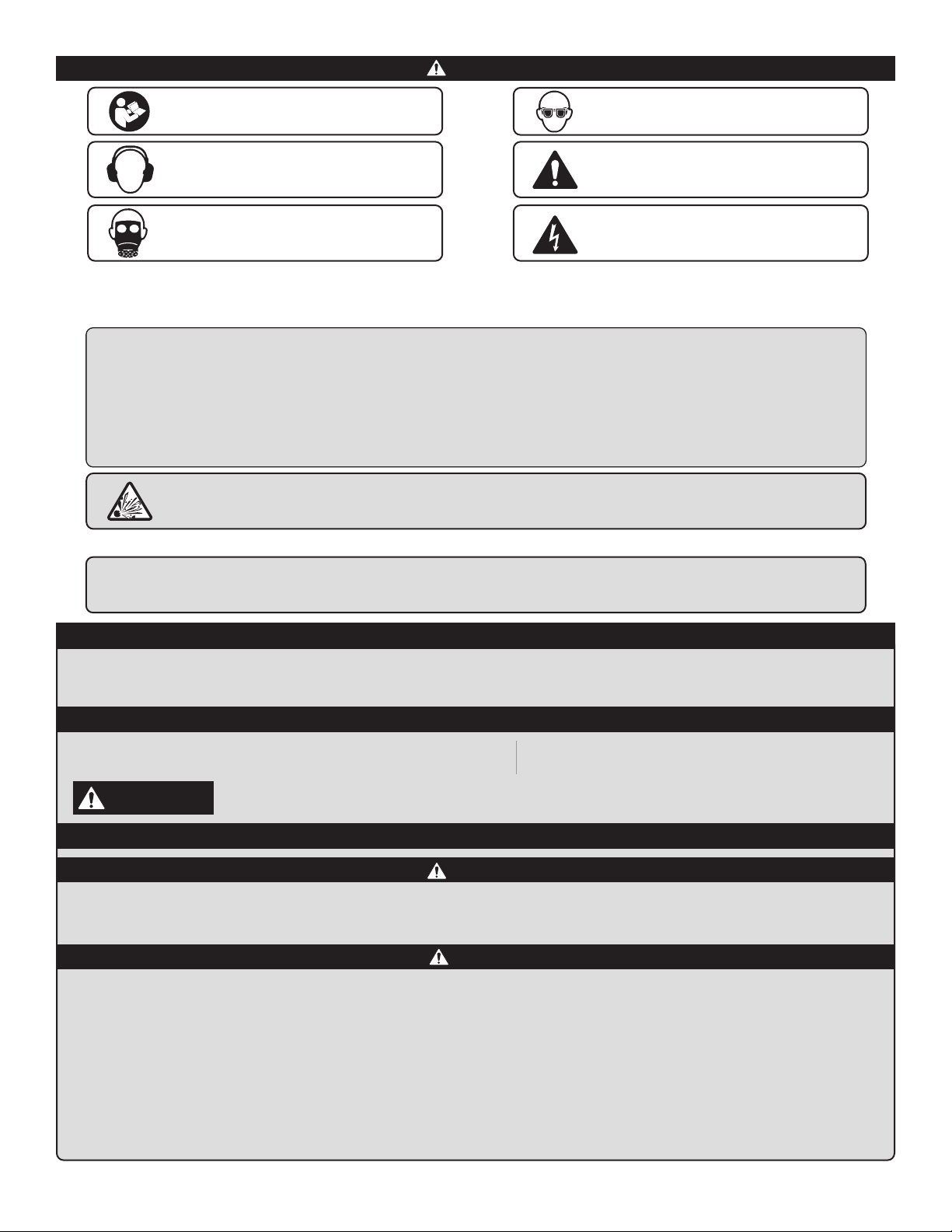
Read and understand tool manual before work starts
to reduce risk of injury to operator, visitors, and tool.
Ear protection to be worn when exposure to sound,
exceeds the limits of applicable Federal, State or
local statues, ordinances and/or regulations.
Respiratory protection to be used when exposed to
contaminants that exceed the applicable threshold
limit values required by law.
Eye protection must be worn at all times,
eye protection to conform to ANSI Z87.1.
Practice safety requirements. Work alert, have
proper attire, and do not operate tools under the
inuence of alcohol or drugs.
Electric shock hazard. Avoid bodily contact with
grounded objects, bodies of water. Do not damage
cord set.
3
Tool Intent:
This unit must be grounded. If the unit should malfunction or break down, grounding
provides a path of least resistance for electric current to reducethe risk of electric shock.
Where it is critical to avoid shocks or sparks caused by static electricity,
an electrically conductive and grounded air supply hose must be used.
Grounding by means of a ground wire between both ends of the air supply tubing passing through vacuum hose is recommended.
WARNING
GROUNDING INSTRUCTIONS

MAINTENANCE INSTRUCTIONS
• Prevent unintentional starting. Ensure the switch is in the o-position before connecting to power source.
• Do not overreach. Keep proper footing and balance at all times. This enables better control of the equipment in unexpected situations.
• Do not let familiarity gained from frequent use of equipment allow you to become complacent and ignore tool safety principles.
A careless action can cause severe injury within a fraction of a second.
EQUIPMENT USE AND CARE
OPERATION
• Do not use the equipment as a means of transportation.
• Do not transport equipment across uneven or inclined surfaces.
• Do not abuse the cord. Never use the cord for carrying, pulling or unplugging the equipment. Keep cord away from heat, oil, sharp edges or moving parts.
• Stay alert, watch what you are doing and use common sense when operating equipment. Do not use equipment while you are tired or under the inuence
of drugs, alcohol or medication.
• Use personal protective equipment. Always wear eye protection. Protective equipment such as dust masks, non-skid safety shoes, hard hat, or hearing protection
used for appropriate conditions will reduce personal injury.
• Dress properly, Do not wear loose clothing or jewelry. Keep your hair, clothing, and gloves away from moving parts. Loose clothes, jewelry or long hair can be
caught in moving parts.
• Do not use the airline for anything other than what it is intended for. Never use the airline for carrying, pulling or unplugging the equipment. Keep airline away
from heat, oil, sharp edges or moving parts.
• Do not use the DrumVac kit unless fully assembled as intended with drum. Ensure all vacuum connections have been made before turning unit to on position.
• Ensure DbA level while using DrumVac does not superceed acceptable levels per operators shift, based on governing body guidelines.
• The vacuum system will operate by an on/auto/manual switch located on the front of the Motorhead/Vacuum Head Assembly. This switch must be turned on to
activate the Motorhead.
WARNING
• Do not use the equipment or touch any electrically conductive surfaces if switch does not function correctly. Unplug vacuum and seek qualied electrical personnel.
• Store idle equipment out of the reach of children and do not allow persons unfamiliar with the equipment or these instructions to operate the equipment.
• Use the equipment, accessories, etc. in accordance with these instructions, taking into account the working conditions and the work to be performed.
• Regularly clean the equipment’s air vents. The motor’s fan will draw the dust inside the housing and excessive accumulation of dust may cause electrical hazards.
• Do not operate equipment with vacuum head removed from DrumVac assembly.
• Do not operate equipment in explosive environments, such as in the presence of ammable liquids, gases, and or combustible dusts based on NFPA standards.
• Avoid body contact with earthed or grounded surfaces such as pipes and radiators. Ensure you are plugging your system to a grounded plug.
• Do not expose equipment to rain or wet conditions. Water entering equipment will increase the risk of electric shock. Product nameplate depicts dry use only.
• Plug equipment into proper outlet based on model/voltage. Always use a grounded power supply. There is an increased risk of electrical shock with an ungrounded
power supply. If a power extension cord is used, ensure it is rated for associated model and power requirements.
CAUTION
• Do not provide maintinance on equioment in explosive environments, such as in the presence of ammable liquids, gases, and or combustible dusts
based on NFPA standards.
• Use the proper equipment to handle and dump the 55 (208 Liters) Gallon drum when full of collected debris. Keep all surrounding areas free of additional
operators when transport and dumping of drum takes place.
WARNING
CAUTION
• Use only genuine Dynabrade replacement parts to ensure quality.
To order replacement parts, specify Model # and Serial # of your equipment.
• Have your equipment serviced by a qualied repair person using only identical replacement parts.
• Unplug vacuum head power cord before providing all maintenance.
• Important: A preventative maintenance program is recommended whenever dust collection equipment is used.
Ensure vacuum head is placed on a at/sturdy surface before performing maintenance.
4

TROUBLESHOOTING
Decrease in Vacuum Performance
• Make sure the vacuum head power cord is undamaged and plugged into correct power supply.
(If machine still does not start, contact a certied electrician for review and repair).
• Disconnect power supply of DrumVac and check condition of HEPA lter and ensure all vacuum hoses and inlets are free of debris. If damaged, replace with
Dynabrade parts.
• Clean the lter thoroughly and as often as necessary. The lter used inside is water-resistant and washable. To prevent damage, do not use high pressure or
solvent to wash the lter.
• If the lter (P/N 80459) should become damaged or badly clogged and cannot be cleaned, replaced with a new one.
• This vacuum is equipped with an Electronic Thermal Protection Device. If the vacuum stops and the red indicator light appears ON, the unit has shut down as
a result of increased temperature. Once the unit has regained a temperature that is allowable for operation the vacuum will resume operation.
This appliance is for use on a nominal 120-Volt circuit and a grounding attachment plug that looks like the plug illustrated in sketch (A)
GROUNDING INSTRUCTIONS
A
FOR COMMERCIAL USE
DRY VACUUM CLEANERS
INDOOR USE ONLY
5
This appliance must be grounded. If it should malfunction or break down, grounding provides a path of least resistance for electric current to
reduce the risk of electric shock.
This appliance is equipped with a cord having an equipment-grounding conductor and grounding plug.
The plug must be inserted into an appropriate outlet that is properly installed and grounded in accordance with all local codes and ordinances.
WARNING - Improper connection of the equipment-grounding conductor can result in a risk of electric shock. Check with a qualied electrician
or service person if you are in doubt as to whether the outlet is properly grounded.
Do not modify the plug provided with the appliance - if it will not t the outlet, have a proper outlet installed by a qualied electrician.
Make sure that the appliance is connected to an outlet having the same conguration as the plug. No adaptor should be used with this appliance.

ITEM DESCRIPTION P/N QTY
1HEPA FILTER 80459 1
Filter
Vacuum Head Assembly ITEM DESCRIPTION P/N QTY
1SCREW 32149 2
2SCREW 32150 2
3HANDLE 32151 1
4LAYER 2 32152 1
5RED LIGHT 32153 1
6ELECTRIC CORD 32154 1
7STRAIN RELIEF 32155 1
8CABLE CLAMP 32156 1
9SCREW 32157 1
10 SCREW 32158 2
11 CLAMP 32159 1
12 STRAIN RELIEF 32160 1
13 FILTER 32161 1
14 SCREW 32162 9
15 CAP COVER 32163 1
16 LAYER 3 32164 1
17 WASHER 32165 1
18 SCREW 32166 1
19 CLAMP 32167 1
20 CONNECTOR 32168 1
21 JOINT 32169 1
22 SCREW 32170 2
23 BLOCK 32171 1
24 BRACKET 32172 1
25 NIPPLE 32173 1
26 GASKET 32174 1
27 SCREW 32175 9
28 SCREW 32176 3
29 SCREW 32177 1
30 LAYER 4 32178 1
31 RING 32179 1
32 CAP/ADAPTER 32180 1
33 GASKET 32181 1
34 MOTOR 32182 1
35 GASKET 32183 1
36 ROUND BRACKET 32184 1
37 GASKET 32185 1
38 RING MUFFLER 32186 1
39 SCREW 32187 4
40 GASKET 32188 1
41 INSERT 32189 1
42 MUFFLER 32190 6
43 CAP 32191 2
44 BASE 32192 1
Model No. Head
Replacement
61200 63600
ITEM DESCRIPTION P/N QTY
1GASKET 32193 1
2 SUPPORT 32194 1
3SCREW 32195 4
4BRACKET FILTER 32196 2
5LOCK FILTER 32197 1
6DIFFUSER 32198 1
6

Vacuum Head
Assembly
Model No. Head
Replacement
61201 63605
51
52
50
48
20
21
22
27
28
47
43
53
46
54
32
49
61
63
64
65
71
72
36
37
45
42
41
40
39
23
38
55
29
30
33
35
58
66
67
68
69
70
59
60
8
11
12
19
5
7
1
9
10
6
4
3230V
2
13
14
15
31
16
17
44
18
57
56
75
74
73
26
24
25
62
3120V
ITEM DESCRIPTION P/N
1 Handle 80460
2
Cord, Model 61401
Cord, Model 61421
Cord, Model 61403
Cord, Model 61409
Cord, Model 61413
Cord, Model 61415
80440
80482
80480
80485
80481
80230
3Strain Relief – 120 V
Strain Relief – 230 V
80495
80486
4Clamp – 120 V
Clamp – 230 V
N/A
80258
5 Screw 80235
6 Screw 80414
7 Screw 80232
8 Cover, Top 80461
9 Screw 80402
10 Terminal Board – 120 V
Terminal Board – 230 V
80415
80487
11 Switch On/Off 80475
12 Switch Tool Select 80450
13
Socket, Model 61401
Socket, Model 61421
Socket, Model 61403
Socket, Model 61409
Socket, Model 61413
Socket, Model 61415
80488
N/A
80492
80493
80494
N/A
14 Screw 80423
15 Nut 80406
16 Lamp, Red 80477
17 Lamp, Orange 80451
18 Pressure Sensor 80425
19 Switch Pocket Cover 80428
20 Filter Bracket 80419
21 Screw 80414
22 Guide 80405
23 Cover Cap 80284
24 Electric Card - 2 Speed – 120 V
Electric Card - 2 Speed – 230 V
80468
80489
25 Sleeve 80472
26 Screw 80232
27 Cover, Bottom 80467
28 Washer 80420
29 Screw 80418
30 Clamp 80173
31 Sleeve 80472
32 Check Valve 80446
33 Electrovalve – 120 V
Electrovalve – 230 V
80458
80490
34 Connector 80449
35 Elbow 80447
36 Tube (per Meter) 80401
37 Pressure Reducer 80439
38 Washer 80420
39 Elbow 80447
40 Reducer 80434
41 Valve 80436
42 Connector 80435
43 Air Tank 80432
44 Safety Valve 80437
45 Tube 80438
46 Guide 80405
47 Gasket 80448
48 Electronic Card 80445
49 Bracket 80245
50 Electronic Card 80430
51 Screw 80235
52 Bracket 80172
53 Screw 80255
54 Screw 80255
55 Screw 80413
56 Heat Sensor 80452
57 Thermoregulator 80422
58 Motor Mount 80478
59 Ring 80470
60 Cap 80442
61 Gasket 80290
62 Motor – 120 V
Motor – 230 V
80462
80491
63 Gasket 80426
64 Spacer 80443
65 Gasket 80290
66 Filter 80441
67 Screw 80235
68 Gasket 80290
69 Plug 80471
70 Muffler 80416
71 Cap 80417
72 Base 80469
73 Nipple 80298
74 Washer 80170
75 Tube 80171
76 Diffuser 80444
77 Gasket 80234
78 Cartridge Support 80479
79 Filter Support 80457
80 Screw 80243
81 Locking Staff 80431
Vacuum Head
Complete Assembly
USA/Canada, 20 Amp - 61401
USA/Canada, 15 Amp - 61421
UK - 61403
CEE7 - 61409
Switzerland - 61413
International - 61415
81
76
77
78
79
80
Replacement Vacuum Head Assembly
Vacuum Model Head Replacement
61401 61601
61421 61621
61403 61603
61409 61609
61413 61613
61415 61615
ITEM DESCRIPTION P/N
1 Handle 80460
2
Cord, Model 61401
Cord, Model 61401
Cord, Model 61401
Cord, Model 61401
Cord, Model 61401
Cord, Model 61401
80440
80482
80480
80485
80481
80230
3Strain Relief – 120 V
Strain Relief – 230 V 80495
80486
4Clamp – 120 V
Clamp – 230 V N/A
80258
5 Screw 80235
6 Screw 80414
7 Screw 80232
8Cover, Top 80461
9 Screw 80402
10 Terminal Board – 120 V
Terminal Board – 230 V 80415
80487
11 Switch On/O 80475
12 Switch Tool Select 80450
13
Socket, Model 61401
Socket, Model 61421
Socket, Model 61403
Socket, Model 61409
Socket, Model 61413
Socket, Model 61415
80488
N/A
80492
80493
80494
N/A
14 Screw 80423
15 Nut 80406
16 Lamp, Red 80477
17 Lamp, Orange 80451
18 Pressure Sensor 80425
19 Switch Pocket Cover 80428
20 Filter Bracket 80419
21 Screw 80414
22 Guide 80405
23 Cover Cap 80284
24 Electric Card - 2 Speed – 120 V
Electric Card - 2 Speed – 230 V 80468
80489
25 Sleeve 80472
26 Screw 80232
27 Cover, Bottom 80467
28 Washer 80420
29 Screw 80418
30 Clamp 80173
31 Sleeve 80472
32 Check Valve 80446
33 Electrovalve – 120 V
Electrovalve – 230 V 80458
80490
34 Connector 80449
35 Elbow 80447
36 Tube (per Meter) 80401
37 Pressure Reducer 80439
38 Washer 80420
39 Elbow 80447
40 Reducer 80434
41 Valve 80436
42 Connector 80435
43 Air Tank 80432
44 Safety Valve 80437
45 Tube 80438
46 Guide 80405
47 Gasket 80448
48 Electronic Card 80445
49 Bracket 80245
50 Electronic Card 80430
51 Screw 80235
52 Bracket 80172
53 Screw 80255
54 Screw 80255
55 Screw 80413
56 Heat Sensor 80452
57 Thermoregulator 80422
58 Motor Mount 80478
59 Ring 80470
60 Cap 80442
61 Gasket 80290
62 Motor – 120 V
Motor – 230 V 80462
80491
63 Gasket 80426
64 Spacer 80443
65 Gasket 80290
66 Filter 80441
67 Screw 80235
68 Gasket 80290
69 Plug 80471
70 Muer 80416
71 Cap 80417
72 Base 80469
73 Nipple 80298
74 Washer 80170
75 Tube 80171
ITEM DESCRIPTION P/N
76 DIFFUSER 80444
77 GASKET 80234
78 CARTRIDGE SUPPORT 80479
79 FILTER SUPPORT 80457
80 SCREW 80243
81 LOCKING STAFF 80431
7

918014153
12
91116
20 18
2
13 15
6
7
1417
1
ITEM DESCRIPTION P/N
1 Nipple 80429
2 Fitting 80229
3 Guide 80421
4 Bracket 80231
5 Screw 80225
6 T Connector 80433
7 Nipple 80400
8 Sensor Body 80476
9 Sensor Plate 80227
10 Sensor 80241
11 O-Ring 80226
12 Screw 80228
13 Nipple 80220
14 Washer 80221
15 Y Connector 96571
16 Tube (per Meter) 80453
17 Coupling 80222
18 Guide 80421
19 Bracket 80231
20 Screw 80225
ITEM DESCRIPTION P/N
1 HEPA Filter 80459
Filter
Pneumatic Tool Supply Line
Complete Assembly
Tool Supply Line
Complete Assembly
8

Vacuum Head, Filter, Interface Ring and Inlet Kit
*Drum and Wheeled Base Sold Separately
Coaxial Vacuum Hose Assembly
(QTY 2) – Part no. 32005 1-1/4” Dia. x 20’ (32 mm x 6m)
*For use with DrumVac Kit 61201
ITEM DESCRIPTION P/N
11” VAC HOSE, STATIC CONDUCTIVE, 20 FT N/A
2OVERHOSE ASSEMBLY 31890
4PLUG - 1/4 NPT, FEMALE 95677
5HOSE - 5/16” ID X 20 FT N/A
6CRIMP FREE 8 MM ID FITTING, 1/4 NPT MALE (2) 94897
7HOSE CUFF, 1” THREAD - 1 1/2” CONNECTION 62574
8COUPLER - 1/4 IN. FPT MEGAFLOW 95674
9HOSE CUFF, 1” THD. TO 1” NON THD. 31900
10 6 IN. MINI CABLE TIE (2) 98668
1
2
4
5
6
7
8
9
10
6
96746 General Purpose Cleaning Kit
*For use with DrumVac Kit 61200
8
2
3
4
5
6
1
*(2 Pieces)
1
*(2 Pieces)
ITEM DESCRIPTION P/N
1WAND 62341
2REDUCER/TAPERED 62343
3LARGE UTILITY FLOOR TOOL 62342
4SMALL UTILITY FLOOR TOOL 62822
5ROUND BRUSH 62727
6CREVICE TOOL 62821
7CUFF 31999
81-1/2” VACUUM HOSE 62340
7
9
61200 61201
1
2
1
4
3
4
2
3
ITEM DESCRIPTION P/N
1VACUUM HEAD 63600
2HEPA FILTER 80459
3INTERFACE RING 62347
4SINGLE INLET 32012
ITEM DESCRIPTION P/N
1VACUUM HEAD 63605
2HEPA FILTER 80459
3INTERFACE RING 62347
4Y INLET 32011

Description of Electric Controls
(B) BLACK ELECTRIC SWITCH (I O II)
(select dierent working modes)
MODE “0”: machine is o
MODE “I”: the motors are working with cyclic cleaning of the cartridge lter
MODE “II”: Electric control system is in automatic mode and the cleaning of the cartridge lter are working.
When the tool is switched o, after about 4 seconds the vacuum cleaner motor will switch o.
WHITE SLIDE SWITCH (I II) (optional)
POSITION “I”: low speed
1 user – 1 exible hose
POSITION “II”: high speed
2 users – 2 exible hoses
ORANGE INDICATOR LIGHT
Connected to a pressure switch, when it lights means that the cartridge lter (essential lter) is clogged
and it must be replaced.
RED INDICATOR LIGHT
It turns on when the thermal protection that stops the motor is activated. The thermal protection works
when the temperature of the air coming out from the motor is about 85°C. The motor overheating is due
to an obstructed lter cartridge.
COMPONENTS AND FEATURES
WARNING
• The manufacturer is not responsible for damages to people or things due to an incorrect or negligent use of the ELECTRIC auto on/o device.
• Changes in the electrical connection of the vacuum head could cause serious damages, even the death of the operator, and irreparable damages
to the vacuum head.
10

TECHNICAL SPECIFICATIONS — PORTABLE VACUUM SYSTEMS
HEPA Filter
80459
Filter Lock
80431
Y Inlet
32011
Single Inlet Fitting
32012
Interface Ring
62347
55 Gallon Drum
32016
Vac Hose
32005
General Purpose Cleaning Kit
96746
Wheeled Base
32010
8989 Sheridan Drive • Clarence, NY 14031-1419 • Phone: (716) 631-0100 • Fax: 716-631-2073 • International Fax: 716-631-2524
©DYNABRADE, INC., 2022
DYNABRADE, INC. www.dynabrade.com
ACCESSORIES
REPLACEMENT PARTS
DYNABRADE, INC. www.dynabrade.com
8989 Sheridan Drive
•
Clarence, NY 14031-1419
•
Phone: (716) 631-0100
•
Fax: 716-631-2073
•
International Fax: 716-631-2524
© DYNABRADE, INC., 2016
TECHNICAL SPECIFICATIONS – PORTABLE VACUUM SYSTEMS
Model No.............................All Models (Reference Pg. 1)
Noise Level ........................ 73,2 dB(A)
Air Pressure........................ 80 to 150 PSIG (5.6 to 10.4 kg/cm2)
Filter.................................... H.E.P.A. (0.3 micron)
Unit Capacity Size .............. 24 gallon/90 liter
No. of Vacuum Outlets........ 2
No. of Pneumatic Outlets .. 2
Construction ...................... Stainless Steel Drum (Canister)
Remainder: Plastic and Metal Components.
Dust & Debris Collection.... Cloth Bag, H.E.P.A.(0.3 micron).
Standard Accessories ........ 2 Pieces of 1-1/4" I.D. x 20' Long Flexible Vacuum
Hose with Built-In 3/8" I.D. Air Supply Tubing
Standard Vacuum Hose...... (2) 20' x 1-1/4" Light Weight Coaxial Hose
(6M x 32mm)
Vacuum Control.................. One Tool / Two Tool
Cord Set .............................. 27' (8M)
14HA
“M” CLASS DRY VACUUM
Model No. Description Powered By Noise Level
dB(A)
Air Pressure
PSIG
Filter
H.E.P.A. Region Supply Unit Capacity
Size Supporting Accessories Operators Cord
Set
61200 General Purpose
120/60 Hz 75 80 - 150
(5.6 - 10.4 kg/cm2)0.3 micron US/CA 15 Amp 55 Gallon
(208 Liter)
96746 Single
27’ (8M)
61201 For use with tools 32005 Dual
Additional Specications: Suggested Air Supply Line to all DrumVac Kits should be: 1/2” (13mm) minimum.
This manual suits for next models
1
Table of contents
Other Dynabrade Vacuum Cleaner manuals

Dynabrade
Dynabrade 61300 User manual

Dynabrade
Dynabrade 61300 User manual

Dynabrade
Dynabrade C-10EX User manual

Dynabrade
Dynabrade 61300 User manual

Dynabrade
Dynabrade RaptorVac 61202 Guide

Dynabrade
Dynabrade DETACHABLE TANK SERIES Installation instructions

Dynabrade
Dynabrade 61496 User manual

Dynabrade
Dynabrade 61495 User manual

Dynabrade
Dynabrade 61461 User manual

Dynabrade
Dynabrade 61500 User manual