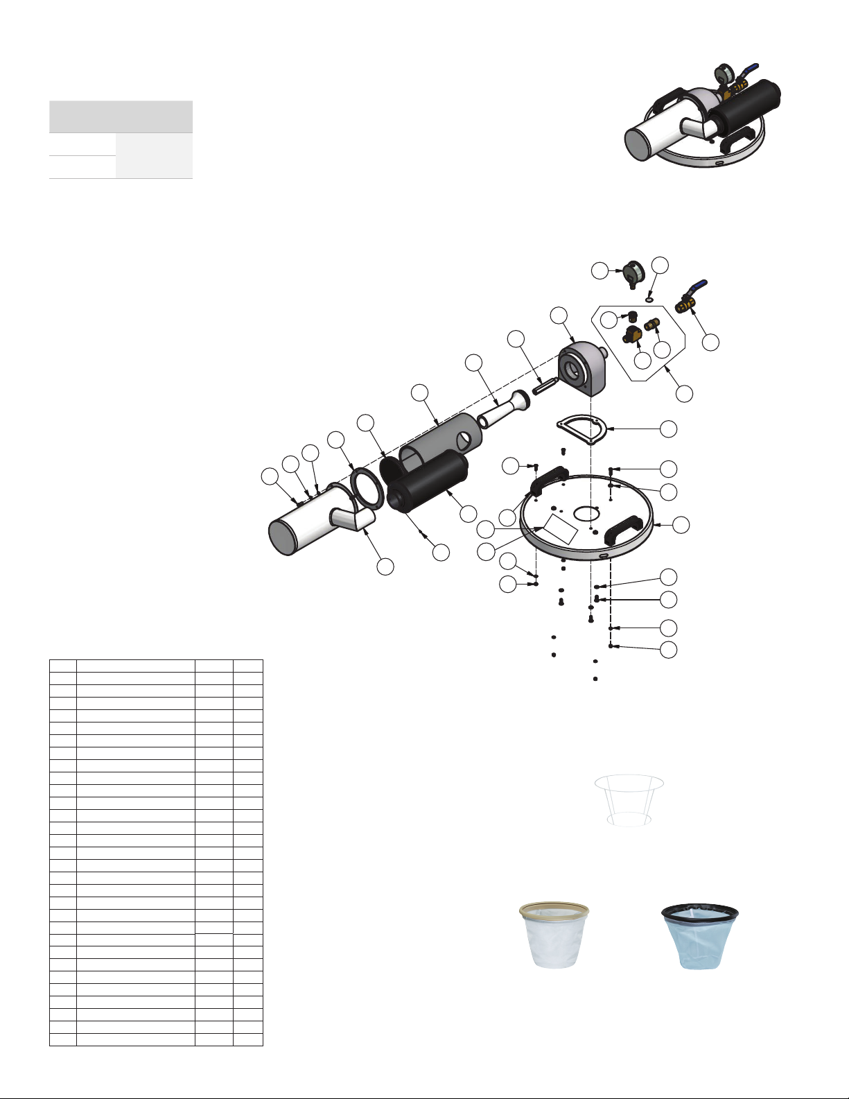
“M” CLASS DRY VACUUM
When employed in accordance with their intended
use, the industrial vacuum cleaners described in
these operating instructions are suitable for
picking up non-ammable, dry dusts.
They correspond to dust class “M” in accordance to:
EN 60335-2-69. By SLG, Germany
Pneumatic Drum Vacuum
High Volume Dust & Chip Collection Systems
Safety, Operation and Maintenance - Save This Document and Educate All Personnel
Find The Most Current Oering of Support Documents and Accessories at www.Dynabrade.com
PD22-15
November, 2022
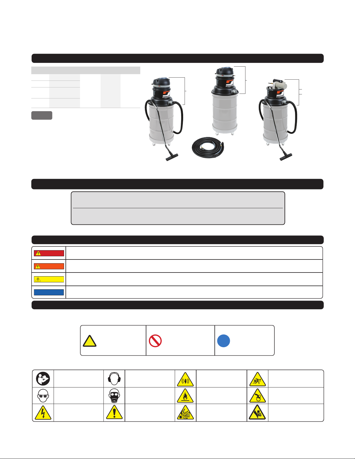
*Drum and wheeled base sold separately
VACUUM
SAFETY SIGNAL WORDS
SAFETY SYMBOLS
ADDITIONAL SAFETY REFERENCE MATERIALS ARE AVAILABLE AT WWW.DYNABRADE.COM
Refer to instruction
manual/booklet
Hearing protection must
be worn
Eye protection must
be worn
Respiratory protection must
be worn
Electric shock hazard Safety Alert
Vibration hazard Air hose hazard
Fire hazard Entanglement hazard
Explosion hazard Crush hazard
Indicates a hazardous situation that, if not avoided, will result in death or serious injury.
This signal word is to be limited to the most extreme situations.
Indicates a hazardous situation that, if not avoided, could result in death or
serious injury.
Indicates a hazardous situation that, if not avoided, could result in minor or moderate
injury. It may also be used without the safety alert symbol as an alternative to
“NOTICE.”
Is the preferred signal word to address practices not related to personal injury. The safety alert symbol
shall not be used with this signal word. As an alternative to “NOTICE”, the word “CAUTION” without
the safety alert symbol may be used to indicate a message not related to personal injury.
DANGER
WARNING
CAUTION
NOTICE
Warning - A black
graphical symbol inside a
yellow triangle with a
black triangular band
defines a safety sign that
indicates a hazard.
Prohibition - A black
graphical symbol inside a
red circular band with a
red diagonal bar defines a
safety sign that indicates
that an action shall not be
taken or shall be stopped.
Mandatory Action- A
white graphical symbol
inside a blue circle defines
a safety sign that
indicates that an action
shall be taken to avoid a
hazard.
Dynabrade Inc. safety labels/symbols follow the guidelines outlined in ISO 3864. In order to help users understand the
meaning of the safety labels/symbols, the standard allows the reproducing of the figures and captions below. Some colored
symbols are reproduced in this document in grayscale. A complete color version may be found at www.dynabrade.com.
Geometric surround shapes:
This document must be read and understood by operating personnel and safety manager.
Protection to operating personnel, as well as adjacent areas, shall be maintained at all times.
The user and/or the user's employer shall conduct a risk assessment of workplace hazards including exposure limits.
Always comply with: General Industry Safety & Health Regulations (www.osha.gov), International Organization for
Standardization (www.iso.org) and Regional Regulations.EN Standards for Hand Held Non-Electric Power Tools
(www.cen.eu), American National Standards Institute (www.ansi.org), Compressed Air and Gas Institute (www.cagi.org).
GENERAL AND TOOL SPECIFIC SECTIONS MUST BE READ AND UNDERSTOOD BEFORE OPERATING ANY PORTABLE PNEUMATIC TOOL!
For consistency Dynabrade Inc. also uses the above symbols and word denitions in collateral material, which includes this Pneumatic Tool Safety Guidelines. For product safety information in
Product Manuals, Instructions, and other Collateral Materials, Dynbarade Inc. adheres to ANSI Z535.6-2006.
Dynabrade Inc. safety labels/symbols follow the guidelines outlined in ISO 3864. In order to help users understand the meaning of the safety labels/symbols, the standard allows the reproducing
of the gures and captions below. Some colored symbols are reproduced in this document in grayscale. A complete color version may be found at www.dynabrade.com.
Geometric surround shapes:
SAFETY SIGNAL WORDS
SAFETY SYMBOLS
Refer to instruction
manual/booklet
Eye protection must
be worn
Electric shock hazard
Hearing protection must
be worn
Respiratory protection must
be worn
Safety Alert
Vibration hazard
Fire hazard
Explosion hazard
Air hose hazard
Entanglement hazard
Crush hazard
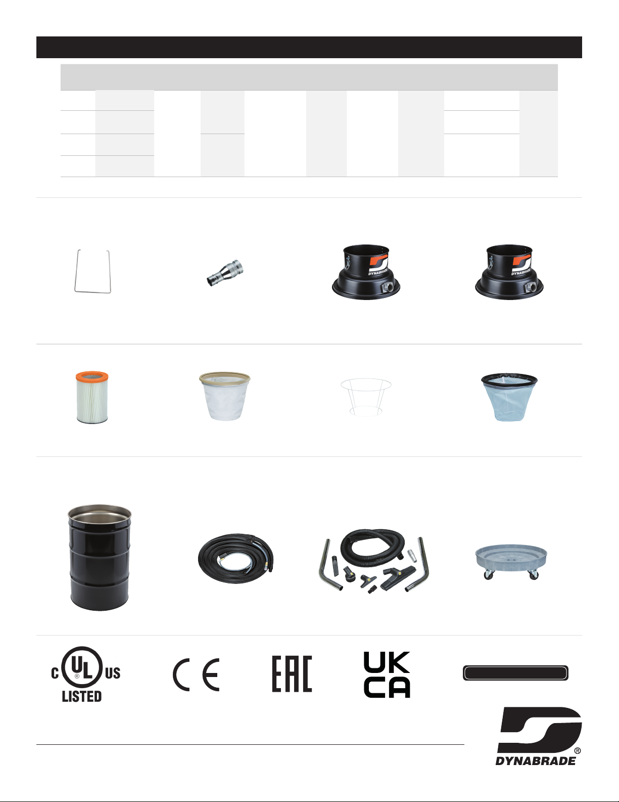
Model No. Description Powered By Air Supply Capacity
61202 General Purpose
Pneumatic 3/4” NPT 55 Gallon
(208 Liters)
61203 For use with tools
61204 General Purpose
Dry Heavy Chip
61205 General Purpose
Wet
61202 61204 - DRY
61205 - WET
Warning - A black
graphical symbol inside a
yellow triangle with a black
triangular banddenes a safety
sign that indicates a hazard.
Prohibition - A black graphical
symbol inside a red circular band
with a red diagonal bar denes a
safety sign that indicates that an
action shall not be taken or shall
be stopped.
Mandatory Action - A white
graphical symbol inside a
blue circle denes a safety
sign that indicates that an
action shall be taken to
avoid a hazard.
DANGER
WARNING
CAUTION
NOTICE
DANGER
WARNING
CAUTION
NOTICE
DANGER
WARNING
CAUTION
NOTICE
Indicates a hazardous situation that, if not avoided, will result in death or serious injury. This signal word is to be limited to the most extreme
situations.
Indicates a hazardous situation that, if not avoided, could result in death or serious injury.
Indicates a hazardous situation that, if not avoided, could result in minor or moderate injury. It may also be used without the safety alert
symbol as an alternative to “NOTICE.”
Is the preferred signal word to address practices not related to personal injury. The safety alert symbol shall not be used with this signal word. As
an alternative to “NOTICE”, the word “CAUTION” without the safety alert symbol may be used to indicate a message not related to personal injury.
DANGER
WARNING
CAUTION
NOTICE
1
61203
32005