Dynabrade 61500 User manual

Read and understand tool manual before
work starts to reduce risk of injury to
operator, visitors, and vacuum.
Eye protection must be worn
at all times, eye protection to
conform to ANSI Z87.1.
Respiratory protection to be used when
exposed to contaminants that exceed the
applicable threshold limit values required by law.
Electric shock hazard. Avoid bodily contact with
grounded objects, bodies of water.
Do not damage cord set.
WARNIN
G
Ear protection to be worn when exposure to sound,
exceeds the limits of applicable Federal, State or local
statues, ordinances and/or regulations.
Read and understand this tool manual before operating your tool. Follow all safety rules for the protection of operating personnel as well
as adjacent areas. Always operate, inspect and maintain this vacuum in accordance with the American National Standards Institute
(ANSI) Safety Code. For additional safety information, refer to Safety Requirements for applicable State and Local Regulations.
Some dust created by sanding, grinding, drilling, and other construction activities contain chemicals known to cause cancer, birth
defects or other reproductive harm. Some examples of these chemicals are:
• Lead from lead-based paints
• Crystalline silica from bricks and cement and other masonry products
• Arsenic and chromium from chemically treated lumber
Your risk from these exposures varies, depending on how often you do this type of work.To reduce your exposure to these chemicals:work in a well
ventilated area, and work with approved safety equipment, such as those dust masks that are specially designed to filter out microscopic particles.
Practice safety requirements.Work alert,
have proper attire, and do not operate tools under
the influence of alcohol or drugs.
FIND THE MOST CURRENT OFFERING OF SUPPORT DOCUMENTS AND ACCESSORIES AT WWW.DYNABRADE.COM
Model 61500
Model
61500 - 115V, 60Hz, 11amp
Reorder No. PD10.33
IMPORTANT SAFETY INSTRUCTIONS - READ BEFORE USE
When operating this equipment, basic precautions should always be strictly followed including the instructions listed below:
Industrial Portable Vacuum
Operating Manual
This Portable Vacuum System has been developed as a safe, portable,
mobile, yet powerful industrial tool for commercial use. To ensure that
this quality equipment is properly used and maintained to its full
capability, please carefully read the following safety instructions and
operating procedures before commencement of the operation.
1. Do not leave appliance when plugged in. Unplug from outlet when not in use and before servicing.
2. Do not expose to rain. Store indoors.
3. Do not allow to be used as a toy. Not to be used by children.
4. Use only as described in this manual. Use only manufacturers's recommended attachments.
5. Do not use with damaged cord or plug. If appliance is not working as it should, has been dropped, damaged, left outdoors, or dropped into water,
return it to a service center.
6. Do not pull or carry by cord, use cord as a handle, close a door on cord, or pull cord around sharp edges or corners. Do not run appliance over cord.
Keep cord away from heated surfaces.
7. Do not unplug by pulling on cord. To unplug, grasp the plug, not the cord.
8. Do not handle plug or appliance with wet hands.
9. Do not put any object into openings. Do not use with any opening blocked; keep free of dust, lint, hair and anything that may reduce air flow.
10. Keep hair, loose clothing, fingers and all parts of the body away from openings and moving parts.
11. Do not vacuum anything that is burning or smoking, such as cigarettes, matches or hot ashes.
12. Do not use without filters in place.
13. Turn off all controls before unplugging.
14. Use extra care when cleaning on stairs.
15. Do not pick up flammable or combustible liquids such as gasoline, or use in areas where they may be present.
16. Connect to a properly grounded outlet only.
17. Use only original spare parts.
- To reduce the risk of fire, electric shock, or injury:
(continued on next page)
Buy parts on line at https://Dynashop.co.uk/ for all things Dynabrade

2
ASSEMBLY INSTRUCTIONS
1. While opening the carton, carefully inspect outside of the carton for
any sign of transportation damage, and if so, notify your shipper
immediately.
2. Remove motorhead and HEPA filter assembly from the first box and
tank/dolly assembly from the second box. Remove accessories from
vacuum tank.
3. Install disposable vacuum bag (included) inside bag restrainer and
connect to the manifold near the bottom of the canister of the
vacuum. The bag restrainer keeps the bag from over expanding.
4. Install the HEPA filter assembly with a pre-filter onto the tank.
5. Return Motorhead Assembly to the unit making sure the protruding
fitting mates with the recess on the HEPA filter and lock the four rim
latches to secure Motorhead/Vacuum Head Assembly in position.
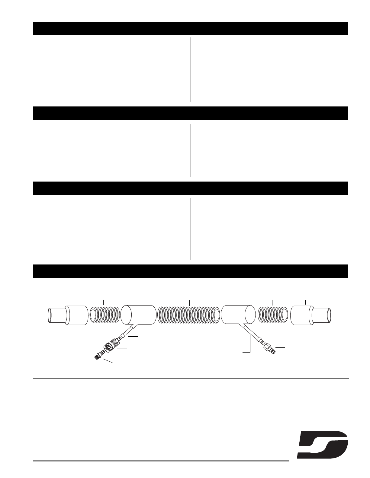
6. On the vacuum hose assembly, note that the air line (the smaller of
the two) protrudes at both ends and is longer than the vacuum hose.
7. Install both quick coupler (P/N 98271) male ends to air outlets
located on vacuum head assembly.
8. Insert vacuum hoses.
9. Install air supply inlet fitting (1/2" NPT female threads - P/N 98271)
to the back side of Motorhead Assembly. Connect air supply, air
pressure should be adjusted according to the pressure requirement
of the air tools you are using. Do not exceed 110 PSIG (7.6 Bar).
Some pressure drop is unavoidable between the main air supply and
the air tools due to internal flow resistance in a long air hose.
1/2" INTERNAL DIAMETER SUPPLY AIR LINE is recommended.
Set regulator by installing an in-line pressure gage (Part No.
94315) at the inlet of the air tool being used. Run the tool and
adjust regulator such that there is 90 PSIG/6.2 Bar @ the
tool inlet.
The installation of a Dynabrade Filter-Regulator-Lubricator (FRL
Part No. 10681) is highly recommended to protect the unit and
the air tools.
Where it is critical to avoid shocks or sparks caused by static
electricity, an air supply hose which is electrically conductive
must be used.
10. Plug unit in and green light will light.
11. Flip switch to “ON” for normal control of unit; flip to “AUTO” to
control vacuum with air tool use.
12. Connect your Dynabrade air tool or accessory and you are now
ready for working with the Dynabrade Portable Vacuum System.
Refer to the drawing and parts list for the name and location of parts.
IMPORTANT SAFETY INSTRUCTIONS (CONT.)
After finishing work:
1. Switch off the vacuum and unplug the power cord.
2. Wind up the power cord.
3. Dispose of collection filter bag.
4. Clean the vacuum inside and outside by suction and wiping.
5. Store the vacuum indoors in clean, dry place.
* This appliance is provided with an automatically reset thermal limiter to avoid damage to the motor.
SAVE THESE INSTRUCTIONS
INSTRUCTIONS TO BE STRICTLY FOLLOWED
•Components used in packaging (i.e. plastic bags) can be dangerous: keep away from children and animals.
•ATTENTION: This machine cannot be utilized outdoor with rainy weather.
•The use of this machine for anything not specified in its manual may be dangerous and must be avoided.
•The suction nozzle should be kept away from the body, especially from delicate areas such as eyes, ears and mouth.
•The equipment should be correctly assembled before use.
•Ensure that power socket used is correct for the machine plug.
•Ensure that the voltage indicated on the rating plate is the same as the power supply voltage.
•WARNING: This machine is not designed for picking up health endangering dusts (i.e. fireplace ash) or inflammable/explosive substances.
•Never leave the equipment unattended while in use.
•Never use this equipment to pick up any kind of hazardous liquids.
•Always remove the plug from the socket before carrying out any operation with the machine or whenever the machine remains unattended or can be
handled by children or people not conscious.
•The power cord should not be used to pull or lift the machine.
•Never immerse the machine in water for cleaning nor use pressure water jets to wash it.
•Should the power cord be damaged, this must be either replaced by the manufacturer or by its service center or in case by a person having similar skills,
so as to prevent any risk.
•If you use extension cables make sure they are placed on dry surfaces and protected from eventual water jets.
•Service and repairs must be carried out by qualified personnel only. Replacement parts for the machine must be original spare parts only.
•The manufacturer cannot be held responsible for any damage/injury caused to persons or property, because of the incorrect use of the machine due to
procedures being used which are not specified in this manual.
Buy parts on line at https://Dynashop.co.uk/ for all things Dynabrade

3
TOP VIEW
Timer
360
Pressure
1415NC
Vacuum
Relay
Vacuum
Low
Hi
Pressssure
1411415
Relay
Assembly for
Wet Applications
Hepa Filter
Assembly for
Dry Applications
Wet Vacuum
Port
Dry Vacuum
Port
1
2
6
5
4
10
9
8
21
22
13
19
20
14
23
15
16
17
18
12
11
7
3
COMPLETE ASSEMBLY DIAGRAM
ITEM PART NO. DESCRIPTION
1 62012 Exhaust Hose
2 62008 Power Cord
3 62017 Conductive Gasket
4 62016 Air Outlet (as req.)
5 62021 On/Off Differential
6 62005 Circuit Breaker
7 62018 Strain Reliever
8 62010 Relay
9 62014 Motor (115V)
10 62001 Switch
11 62007 Latches (as req.)
12 62003 Pre-Filter
13 62002 Plug
14 62004 Collection Filter
15 62015 "Y" Connector
16 62006 Caster (as req.)
17 62011 Dolly Assembly
18 62000 Wheel (as req.)
19 62018 Gasket
20 62013 HEPA Filter
21 62023 Water Guard
22 62022 Ball
23 62025 Bag Restrainer
62019
62020
Replacement Motor Brush Set
Part No. 62024
Red Yellow
Power Switch
AUTO
OFF
ON
Motor Head Light Panel
Green
Power
On
when lit
Change
Filter
when lit
Align
filter and
motorhead
when lit
Buy parts on line at https://Dynashop.co.uk/ for all things Dynabrade

DYNABRADE®
www.dynabrade.com
© DYNABRADE, INC., 2010 PRINTED IN USA PD10.33_09/10
DYNABRADE, INC.
8989 Sheridan Drive • Clarence, New York 14031-1419 • Phone: (716) 631-0100
Fax: 716-631-2073 •
US Consumers Call Toll Free: 1-800-828-7333
DYNABRADE INTERNATIONAL
8989 Sheridan Drive • Clarence, New York 14031-1419 • Phone: (716) 631-0100
Fax: 716-631-2524 •
Canadian Consumers Call Toll Free: 1-800-344-1488
DYNABRADE EUROPE S.à r. l.
Zone Artisanale • L-5485 Wormeldange-Haut, Luxembourg
Phone: +352 768 494 1 • Fax: +352 768 495
DYNABRADE DO BRASIL
Rua Mário Fongaro • 421 – Vila Marlene • São Bernardo do Campo
SP – CEP 09732-530 • Telefax: (11) 4124-6040
TECHNICAL SPECIFICATIONS – INDUSTRIAL VACUUM SYSTEM
Model No. ........................ 61500
Noise Level ...................... 76 Decibels
Air Pressure .................... 90 PSIG (6.2 Bar)
Filter ................................ H.E.P.A. (0.3 micron)
Unit Capacity Size............ Dry: 10 gallon (44 liter)
.......................................... Wet: 12 gallon (45.4 liter)
Static H2O Lift .................. 88" (2.2 m)
Air Displacement ............ 130 cfm
No. of Vacuum Outlets .... 2
No. of Pneumatic Outlets 2 (3/8" NPT)
Construction .................... Stainless Steel Canister
Remainder: Plastic and Metal Components.
Dust & Debris Collection Pre Filter, H.E.P.A.(0.3 micron) Filter
Collection Filter.
Standard Vacuum Hose .. (2) 20' x 1-1/4" Light Weight Coaxial Hose
(Conductive, P/N 31960)
Cord Set............................ 37' (11.3 m)
REMOVAL/INSTALLATION OF MOTORHEAD FROM MAIN ASSEMBLY
If the filter element becomes clogged or to clean the inner portions of the
canister the Motorhead Assembly must then be removed to perform
cleaning. When removal becomes necessary for cleaning or other service,
follow the procedures described below.
Removal
1. Unplug the unit before attempting service or maintenance work.
2. Remove Top Lid by unlatching (4) hinges.
3. Use a conventional vacuum cleaner to clean entire inside of
Motorhead Assembly and canister.
Upon completion of the service work, install top lid according to
the following procedure:
Installation
1. Place cleaned unit onto the canister and latch (4)
hinges to properly attach the lid. Unit is now ready for
operation.
OPERATING TIPS AND TROUBLESHOOTING
DO NOT USE A BLOW GUN WHEN CLEANING MOTORHEAD ASSEMBLY.
Decrease in Vacuum Performance
1. If the pre-filter (P/N 62003) should become damaged or badly
clogged, replace with a new one. It is recommended to replace the
pre-filter every third time you replace the collection filter.
2. Check all the vacuum lines for blockage or leakage.
Vacuum Stops During Use
1. This vacuum is protected by both a resettable circuit breaker and an
Electronic Thermal Protection device. If the unit shuts down, check
and reset the circuit breaker. If the unit does not restart the thermal
protection may have shut down as a result of over temperature. Once
it has cooled the unit will restart.
31960 CONDUCTIVE COAXIAL VACUUM HOSE ASSEMBLY
Swivel Cuff
P/N 31907
Cuff
P/N 31904
1-1/4" Vac Hose
P/N 31969
Cuff with Air Line Exit
P/N 31967
Cuff with Air Line Exit
P/N 31967
1-1/4" Vac Hose
P/N 31969
1-1/4" Vac Hose
P/N 31970
Air Line Assembly - 11" (28cm) of Air
Line Assembly will Extend Past the Cuff
Dynabrade Male Plug
P/N 95675
Dynabrade Female Plug
P/N 95677
36" (91cm) of
Air Line
Assembly
will Extend Past
the Cuff
Dynabrade Coupler
P/N 94960
Buy parts on line at https://Dynashop.co.uk/ for all things Dynabrade
Table of contents
Other Dynabrade Vacuum Cleaner manuals

Dynabrade
Dynabrade 61300 User manual

Dynabrade
Dynabrade 61200 Guide

Dynabrade
Dynabrade 61300 User manual

Dynabrade
Dynabrade RaptorVac 61202 Guide

Dynabrade
Dynabrade C-10EX User manual

Dynabrade
Dynabrade 61461 User manual

Dynabrade
Dynabrade 61495 User manual

Dynabrade
Dynabrade DETACHABLE TANK SERIES Installation instructions

Dynabrade
Dynabrade 61496 User manual

Dynabrade
Dynabrade Mini-Raptor Vac 61100 User manual