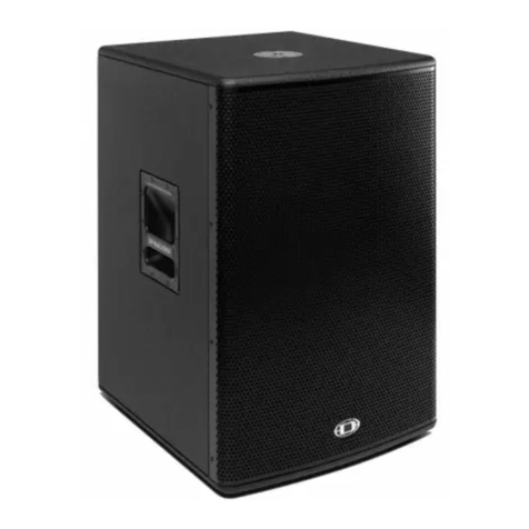
Dynacord POWERSUB 112 User manual

PowerSub 112 | 212
POWERED SUBWOOFER
Owner‘s Manual | Bedienungsanleitung

PS 112 | 212
2

PS 112 | 212
3
CONTENTS
INTRODUCTION . . . . . . . . . . . . . . . . . . . . . . . . . . . . . . . . . . . . . . . . . . . . . . . . . . . . . . . . . . . . . . . . . . . . . . . . . . . . . . . 5
Scope of Delivery, Unpacking and Inspection . . . . . . . . . . . . . . . . . . . . . . . . . . . . . . . . . . . . . . . . . . . . . . . . . . 5
Warranty . . . . . . . . . . . . . . . . . . . . . . . . . . . . . . . . . . . . . . . . . . . . . . . . . . . . . . . . . . . . . . . . . . . . . . . . . . . . . . . 5
INSTALLATION . . . . . . . . . . . . . . . . . . . . . . . . . . . . . . . . . . . . . . . . . . . . . . . . . . . . . . . . . . . . . . . . . . . . . . . . . . . . . . . . 6
Controls, Indicators and Connections . . . . . . . . . . . . . . . . . . . . . . . . . . . . . . . . . . . . . . . . . . . . . . . . . . . . . . . . 6
1 Power on/off indicator (POWER) . . . . . . . . . . . . . . . . . . . . . . . . . . . . . . . . . . . . . . . . . . . . . . . . . . . . . . . . . . . . . . . . . . . . . . . . . . . . . . . . . . 7
2 Mains switch (ON/OFF) . . . . . . . . . . . . . . . . . . . . . . . . . . . . . . . . . . . . . . . . . . . . . . . . . . . . . . . . . . . . . . . . . . . . . . . . . . . . . . . . . . . . . . . . . 7
3 Mains connector (MAINS IN) . . . . . . . . . . . . . . . . . . . . . . . . . . . . . . . . . . . . . . . . . . . . . . . . . . . . . . . . . . . . . . . . . . . . . . . . . . . . . . . . . . . . . 7
4 Limit Indicator (LIMIT) . . . . . . . . . . . . . . . . . . . . . . . . . . . . . . . . . . . . . . . . . . . . . . . . . . . . . . . . . . . . . . . . . . . . . . . . . . . . . . . . . . . . . . . . . . 7
5 Master level control (VOLUME) . . . . . . . . . . . . . . . . . . . . . . . . . . . . . . . . . . . . . . . . . . . . . . . . . . . . . . . . . . . . . . . . . . . . . . . . . . . . . . . . . . . 7
6 Phase Indicator (180°) . . . . . . . . . . . . . . . . . . . . . . . . . . . . . . . . . . . . . . . . . . . . . . . . . . . . . . . . . . . . . . . . . . . . . . . . . . . . . . . . . . . . . . . . . . 7
7 Phase switch (PHASE) . . . . . . . . . . . . . . . . . . . . . . . . . . . . . . . . . . . . . . . . . . . . . . . . . . . . . . . . . . . . . . . . . . . . . . . . . . . . . . . . . . . . . . . . . . 7
8 Output connector for mid/high audio signal (MID/HIGH OUT) . . . . . . . . . . . . . . . . . . . . . . . . . . . . . . . . . . . . . . . . . . . . . . . . . . . . . . . . . . 7
9 Input connector for audio signal (LINE IN) . . . . . . . . . . . . . . . . . . . . . . . . . . . . . . . . . . . . . . . . . . . . . . . . . . . . . . . . . . . . . . . . . . . . . . . . . . 7
10 Output connector (LINE THRU) . . . . . . . . . . . . . . . . . . . . . . . . . . . . . . . . . . . . . . . . . . . . . . . . . . . . . . . . . . . . . . . . . . . . . . . . . . . . . . . . . . 7
Quick Start . . . . . . . . . . . . . . . . . . . . . . . . . . . . . . . . . . . . . . . . . . . . . . . . . . . . . . . . . . . . . . . . . . . . . . . . . . . . . 8
SPECIFICATIONS . . . . . . . . . . . . . . . . . . . . . . . . . . . . . . . . . . . . . . . . . . . . . . . . . . . . . . . . . . . . . . . . . . . . . . . . . . . . . . 15
Block Diagram . . . . . . . . . . . . . . . . . . . . . . . . . . . . . . . . . . . . . . . . . . . . . . . . . . . . . . . . . . . . . . . . . . . . . . . . . . . 15
Frequency Response . . . . . . . . . . . . . . . . . . . . . . . . . . . . . . . . . . . . . . . . . . . . . . . . . . . . . . . . . . . . . . . . . . . . . . 16
Dimensions . . . . . . . . . . . . . . . . . . . . . . . . . . . . . . . . . . . . . . . . . . . . . . . . . . . . . . . . . . . . . . . . . . . . . . . . . . . . . 17
Setup Examples . . . . . . . . . . . . . . . . . . . . . . . . . . . . . . . . . . . . . . . . . . . . . . . . . . . . . . . . . . . . . . . . . . . . . . . . . 18
D-Lite ActiveOne . . . . . . . . . . . . . . . . . . . . . . . . . . . . . . . . . . . . . . . . . . . . . . . . . . . . . . . . . . . . . . . . . . . . . . . . . . . . . . . . . . . . . . . . . . . . . . . . 18
D-Lite ActiveOne extended . . . . . . . . . . . . . . . . . . . . . . . . . . . . . . . . . . . . . . . . . . . . . . . . . . . . . . . . . . . . . . . . . . . . . . . . . . . . . . . . . . . . . . . . 18
D-Lite ActiveTwo . . . . . . . . . . . . . . . . . . . . . . . . . . . . . . . . . . . . . . . . . . . . . . . . . . . . . . . . . . . . . . . . . . . . . . . . . . . . . . . . . . . . . . . . . . . . . . . . 19
D-Lite ActiveFour . . . . . . . . . . . . . . . . . . . . . . . . . . . . . . . . . . . . . . . . . . . . . . . . . . . . . . . . . . . . . . . . . . . . . . . . . . . . . . . . . . . . . . . . . . . . . . . . 19
INHALTSVERZEICHNIS
EINFÜHRUNG . . . . . . . . . . . . . . . . . . . . . . . . . . . . . . . . . . . . . . . . . . . . . . . . . . . . . . . . . . . . . . . . . . . . . . . . . . . . . . . . . 11
Lieferumfang, Auspacken und Überprüfen . . . . . . . . . . . . . . . . . . . . . . . . . . . . . . . . . . . . . . . . . . . . . . . . . . . . . 11
Garantie . . . . . . . . . . . . . . . . . . . . . . . . . . . . . . . . . . . . . . . . . . . . . . . . . . . . . . . . . . . . . . . . . . . . . . . . . . . . . . . 11
INSTALLATION . . . . . . . . . . . . . . . . . . . . . . . . . . . . . . . . . . . . . . . . . . . . . . . . . . . . . . . . . . . . . . . . . . . . . . . . . . . . . . . . 12
Bedienelemente, Anzeigen und Anschlüsse . . . . . . . . . . . . . . . . . . . . . . . . . . . . . . . . . . . . . . . . . . . . . . . . . . . . 12
1 Anzeige Betrieb (POWER) . . . . . . . . . . . . . . . . . . . . . . . . . . . . . . . . . . . . . . . . . . . . . . . . . . . . . . . . . . . . . . . . . . . . . . . . . . . . . . . . . . . . . . . 13
2 Netzschalter (ON/OFF) . . . . . . . . . . . . . . . . . . . . . . . . . . . . . . . . . . . . . . . . . . . . . . . . . . . . . . . . . . . . . . . . . . . . . . . . . . . . . . . . . . . . . . . . . 13
3 Netzeingang (MAINS IN) . . . . . . . . . . . . . . . . . . . . . . . . . . . . . . . . . . . . . . . . . . . . . . . . . . . . . . . . . . . . . . . . . . . . . . . . . . . . . . . . . . . . . . . . . 13
4 Anzeige Limiter (LIMIT) . . . . . . . . . . . . . . . . . . . . . . . . . . . . . . . . . . . . . . . . . . . . . . . . . . . . . . . . . . . . . . . . . . . . . . . . . . . . . . . . . . . . . . . . . 13
5 Eingangspegel-Regler (VOLUME) . . . . . . . . . . . . . . . . . . . . . . . . . . . . . . . . . . . . . . . . . . . . . . . . . . . . . . . . . . . . . . . . . . . . . . . . . . . . . . . . . 13
6 Anzeige Phasendrehung (180°) . . . . . . . . . . . . . . . . . . . . . . . . . . . . . . . . . . . . . . . . . . . . . . . . . . . . . . . . . . . . . . . . . . . . . . . . . . . . . . . . . . . 13
7 Schalter für Phasendrehung (PHASE) . . . . . . . . . . . . . . . . . . . . . . . . . . . . . . . . . . . . . . . . . . . . . . . . . . . . . . . . . . . . . . . . . . . . . . . . . . . . . . 13
8 Ausgang für Mitten- und Hochton-Signal (MID/HIGH OUT) . . . . . . . . . . . . . . . . . . . . . . . . . . . . . . . . . . . . . . . . . . . . . . . . . . . . . . . . . . . . . 13
9 Eingang für Line-Signal (LINE IN) . . . . . . . . . . . . . . . . . . . . . . . . . . . . . . . . . . . . . . . . . . . . . . . . . . . . . . . . . . . . . . . . . . . . . . . . . . . . . . . . . . 13
10 Ausgang für Audio-Signal (LINE THRU) . . . . . . . . . . . . . . . . . . . . . . . . . . . . . . . . . . . . . . . . . . . . . . . . . . . . . . . . . . . . . . . . . . . . . . . . . . . . 14
Quickstart . . . . . . . . . . . . . . . . . . . . . . . . . . . . . . . . . . . . . . . . . . . . . . . . . . . . . . . . . . . . . . . . . . . . . . . . . . . . . . 14
SPECIFICATIONS . . . . . . . . . . . . . . . . . . . . . . . . . . . . . . . . . . . . . . . . . . . . . . . . . . . . . . . . . . . . . . . . . . . . . . . . . . . . . . 15
Block Diagram . . . . . . . . . . . . . . . . . . . . . . . . . . . . . . . . . . . . . . . . . . . . . . . . . . . . . . . . . . . . . . . . . . . . . . . . . . . 15
Frequency Response . . . . . . . . . . . . . . . . . . . . . . . . . . . . . . . . . . . . . . . . . . . . . . . . . . . . . . . . . . . . . . . . . . . . . . 16
Dimensions . . . . . . . . . . . . . . . . . . . . . . . . . . . . . . . . . . . . . . . . . . . . . . . . . . . . . . . . . . . . . . . . . . . . . . . . . . . . . 17
Setup Examples . . . . . . . . . . . . . . . . . . . . . . . . . . . . . . . . . . . . . . . . . . . . . . . . . . . . . . . . . . . . . . . . . . . . . . . . . 18
D-Lite ActiveOne . . . . . . . . . . . . . . . . . . . . . . . . . . . . . . . . . . . . . . . . . . . . . . . . . . . . . . . . . . . . . . . . . . . . . . . . . . . . . . . . . . . . . . . . . . . . . . . . 18
D-Lite ActiveOne extended . . . . . . . . . . . . . . . . . . . . . . . . . . . . . . . . . . . . . . . . . . . . . . . . . . . . . . . . . . . . . . . . . . . . . . . . . . . . . . . . . . . . . . . . 18
D-Lite ActiveTwo . . . . . . . . . . . . . . . . . . . . . . . . . . . . . . . . . . . . . . . . . . . . . . . . . . . . . . . . . . . . . . . . . . . . . . . . . . . . . . . . . . . . . . . . . . . . . . . . 19
D-Lite ActiveFour . . . . . . . . . . . . . . . . . . . . . . . . . . . . . . . . . . . . . . . . . . . . . . . . . . . . . . . . . . . . . . . . . . . . . . . . . . . . . . . . . . . . . . . . . . . . . . . . 19

PS 112 | 212
4
IMPORTANT SAFETY INSTRUCTIONS
1. Read these instructions.
2. Keep these instructions.
3. Heed all warnings.
4. Follow all instructions.
5. Do not use this apparatus near water.
6. Clean only with a dry cloth.
7. Do not cover any ventilation openings. Install in accordance with the manufacturer’s instructions.
8. Do not install near heat sources such as radiators, heat registers, stoves, or other apparatus (including amplifiers) that produce heat.
9. Do not defeat the safety purpose of the polarized or the grounding-type plug. A polarized plug has two blades with one wider than the other. A grounding type plug has two
blades and a third grounding prong. The wide blade or the third prong are provided for your safety. If the provided plug does not fit into your outlet, consult an electrician
for replacement of the obsolete outlet.
10. Protect the power cord from being walked on or pinched particularly at plugs, convenience receptacles, and the point where they exit from the apparatus.
11. Only use attachments/accessories specified by the manufacturer.
12. Use only with the cart, tripod, bracket, or table specified by the manufacturer, or sold with the apparatus. When a cart is used, use caution when moving
the cart/apparatus combination to avoid injury from tip-over.
13. Unplug this apparatus during lightning storms or when unused for a long period of time.
14. Refer all servicing to qualified service personnel. Servicing is required when the apparatus has been damaged in any way, such as power-supply cord or
plug is damaged, liquid has been spilled or orbjects have fallen into the apparatus, the apparatus has been exposed to rain or moisture, does not operate
normally, or has been dropped.
15. Do not expose this equipment to dripping or splashing and ensure that no objects filled with liquids, such as vases, are placed on the equipment.
16. To completely disconnect this equipment from the AC Mains, disconnect the power supply cord plug from the AC receptacle.
17. The mains plug of the power supply cord shall remain readily operable.
18. No naked flame sources, such as lighted candles, should be placed on the apparatus.
19. The product should be connected to a mains socket outlet with a protective earthing connection.
IMPORTANT SERVICE INSTRUCTIONS
CAUTION: These servicing instructions are for use by qualified personnel only. To reduce the risk of electric shock, do not
perform any servicing other than that contained in the Operating Instructions unless you are qualified to do so. Refer
all servicing to qualified service personnel.
1. Security regulations as stated in the EN 60065 (VDE 0860 / IEC 65) and the CSA E65 - 94 have to be obeyed when servicing the appliance.
2. Use of a mains separator transformer is mandatory during maintenance while the appliance is opened, needs to be operated and is connected to the mains.
3. Switch off the power before retrofitting any extensions, changing the mains voltage or the output voltage.
4. The minimum distance between parts carrying mains voltage and any accessible metal piece (metal enclosure), respectively between the mains poles has to be 3 mm and
needs to be minded at all times. The minimum distance between parts carrying mains voltage and any switches or breakers that are not connected to the mains
(secondary parts) has to be 6 mm and needs to be minded at all times.
5. Replacing special components that are marked in the circuit diagram using the security symbol (Note) is only permissible when using original parts.
6. Altering the circuitry without prior consent or advice is not legitimate.
7. Any work security regulations that are applicable at the locations where the appliance is being serviced have to be strictly obeyed. This applies also to any regulations
about the work place itself.
8.
All instructions concerning the handling of MOS-circuits have to be observed.
WEEE RECYCLING/DISPOSAL INSTRUCTIONS
The Wheelie Bin symbol found on the product or in the manual indicates that this product must not be disposed of with other waste. It is in our category the
manufacturer’s responsibility to properly dispose of their waste electrical and electronic equipment (WEEE) at the end of its life. Due to the differences in each EU
country’s management of WEEE, please contact your local distributor. We are committed to facilitate our own electronic-waste-management-system, for the free of
charge return of all EVI Audio GmbH products: Telex, DYNACORD, Electro-Voice and RTS. Arrangements are made with the dealer where you purchased the
equipment from, for the returning of all unusable equipment at no cost, to the factory in Straubing, for environmental protective disposal.
The lightning flash with arrowhead symbol, within an equilateral
triangle is intended to alert the user to the presence of uninsulated
”dangerous voltage” within the product’s enclosure that may be of
sufficent magnitude to constitute a risk of electric shock to per-
sons.
The exclamation point within an equilateral triangle is intended to
alert the user to the presence of important operating and
maintance (servicing) instructions in the literature accompanying
the appliance.
NOTE: SAFETY COMPONENT (MUST BE REPLACED BY ORIGINAL PART)

D 8A
5
1 Introduction
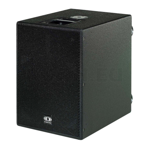
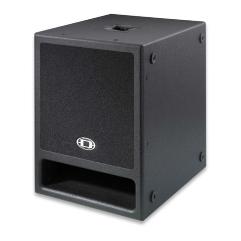
The DYNACORD PowerSub 112 and 212 powered sub-
woofers are perfectly suited for building multi-component
active loudspeaker systems, e.g. an active 3-way system
using powered fullrange speakers like the DYNACORD
D 8A or the DYNACORD D 11A. Due to its vented design
this subwoofers offers much more musical, tight and
punchy bass than typical bandpass designs often found in
this type of product range.
PowerSub 112
The PowerSub 112 is great for enhancing the low frequen-
cy response of active fullrange speakers like the D 8A. De-
spite its light weight and compact dimensions the
subwoofer still produces a very powerful bass line even at
very low frequencies. The 200 W RMS or 400 W Maximum
Amplifier Output Capability class D technology amplifier
modul has an integrated crossover with mid/hi output. The
signal polarity can also be switched if necessary.
PowerSub 212
The PowerSub 212 is a very compact 2 x 12“ subwoofer
with an integrated 2 x 200 W RMS or 2 x 400 W Maximum
Amplifier Output Capability class D technology amplifier
module. The integrated stereo crossover means it‘s simple
to build an active 3-way system with mono subwoofer and
active fullrange speakers. The PowerSub 212 is perfectly
matched with the D 8A or the D 11A and delivers the low-
est bass at the highest sound pressure levels. As with the
PowerSub 112 the sound is always clean, with no distor-
tion, even for the most demanding applications. Four cas-
tors allow easy transportation and handling.
1.1 Scope of Delivery, Unpacking and
Inspection
Carefully open the packaging and take out the cabinet. In-
spect the cabinet’s enclosure for damages that might have
occured during transportation. Each cabinet is examined
and tested in detail before leaving the manufacturing site
to ensure that it arrives in perfect condition at your place.
Please inform the transport company immediately if the
cabinet shows any damage. Being the addressee, you are
the only person who can claim damages in transit. Keep
the cardboard box and all packaging materials for inspec-
tion by the transport company.
Keeping the cardboard box including all packing materials
is also recommended, if the cabinet shows no external
damages.
CAUTION: Do not ship the cabinet in any other than its
original packaging.
Packing the cabinet like it was packed by the manufacturer
guarantees optimum protection from transport damage.
1.2 Warranty
Keep the original invoice that states the purchase/delivery
date together with the warranty certificate at a safe place.
The manufacturer‘s warranty covers all substantial defects
in materials and workmanship for a period of 36 months
from the date of purchase. Liability claims are accepted
solely, when a valid - correctly and completely filled out -
Warranty Registration Form is presented by the original
owner of the product. The warranty does not cover dam-
age that results from improper or inadequate treatment or
maintenance. In case of alteration or unauthorized repairs,
the warranty is automatically terminated.
HINT: This equipment has been tested and found to comply with the limits for a Class A digital device, pursuant to
Part 15 of the FCC Rules. These limits are designed to provide reasonable protection against harmful inter-
ference when the equipment is operated in a commercial environment. This equipment generates, uses, and
can radiate radio frequency energy and, if not installed and used in accordance with the instruction manual,
may cause harmful interference to radio communications. Operation of this equipment in a residental area is
likely to cause harmful interference in which case the user will be required to correct the interference at his
own expense.
•1ActiveSubwoofer
• 1 Owner‘s Manual (this document)
•1MainsCord(lockable)
• 1 Warranty Certificate including Safety Instructions

PS 112 | 212
6
2 Installation
2.1 Controls, Indicators and Connections
1
2
3
4
5
6
7
8
9
10
1
2
3
4
5
6
7
8
9
10

PS 112 | 212
7
1 POWER ON/OFF INDICATOR (POWER)
The POWER LED lights green if the mains switch
is ON and the mains cord is connected correctly.
2 MAINS SWITCH (ON/OFF)
Mains switch for switching the unit‘s power
ON or OFF. The POWER LED lights after
turning the power ON. If the mains cord is
correctly connected, mains voltage is
present and the LED does not light upon
power-on, please contact your local dealer.
3 MAINS CONNECTOR (MAINS IN)
The PowerSub receives its power
supply via the lockable MAINS IN con-
nector. Only the provided power cord
may be used. Connect the PowerSub
only to a mains network, which corre-
sponds to the requirements indicat-
ed on the type plate. Press the yellow
button at the plug to disconnect the
power cord.
4 LIMIT INDICATOR (LIMIT)
Brief blinking of the LIMIT LED indicates that the
power amplifier of the PowerSub is operated at its
limits. Short-term blinking is uncritical, because the
integrated limiter compensates minor distortion. Constant
lighting of the LED indicates that the sound is negatively af-
fected. Reducing the output volume is strongly recom-
mended.
5 VOLUME CONTROL (VOLUME)
Level control for adjusting the power amp’s
overall amplification. Setting the control be-
tween 0 dB and +6 dB is recommended to
avoid signal distortion in signal sources (e.g.
mixer).
6 POLARITY INDICATOR (180°)
The 180° LED lights yellow if the Polarity switch is
pressed and the signal polarity is inverted.
7 POLARITY SWITCH (PHASE)
Select 0° (button not pressed) if the sig-
nal polarity should not be inverted. Select
180° (button pressed) to change the signal polarity by
180°.
8 OUTPUT CONNECTOR FOR MID/HIGH AUDIO SIGNAL (MID/
HIGH OUT)
The upper band of the Power-
Sub‘s integrated crossover (filter
frequency 120 Hz) is available at
this XLR output connector. The
level of the output signal is inde-
pendent of the setting of the level
control VOLUME (”Pre Fader”).
9 INPUT CONNECTOR FOR AUDIO SIGNAL (LINE IN)
Electronically balanced input for
the connection of a line level signal
source such as mixer, signal proces-
sor, etc. Establishing a connection
is possible via phone or XLR-type
plugs. Whenever possible, balanced
signal feed is always preferable to
guard against potential noise or HF-interference.
CAUTION: Before making any connections or discon-
nections, make sure to set the level control
VOLUME to the counterclockwise stop.
10 OUTPUT CONNECTOR (LINE THRU)
The output connector provides the
LINE IN signal for ”carrying through“
the input signal. The level of the out-
put signal is independent of the set-
ting of the level control VOLUME
(”Pre Fader”).
Number PS 112 PS 212
1Power on/off indicator (POWER)
2Mains switch (ON / OFF)
3Mains connector, lockable (MAINS IN)
4Limit indicator (LIMIT)
5Volume control (VOLUME)
6Polarity indicator (180°)
7Polarity switch (PHASE)
8Output connector (XLR) for mid/hi audio signal (MID/HIGH OUT) Output connectors (XLR) for left or right mid/hi audio signal (MID/HIGH OUT L or
MID/HIGH OUT R)
9Input connector (XLR or phone) for line level audio signal (LINE IN) Input connectors (XLR or phone) for left or right line level audio signal (LINE IN
LEFT or LINE IN RIGHT)
10 Output connector (XLR) for line level audio signal (LINE THRU) Output connectors (XLR) for left or right line level audio signal (LINE THRU LEFT or
LINE THRU RIGHT)

PS 112 | 212
8
2.2 Quick Start
CAUTION: After installing the system, first switch on the mixing console and position the mixer’s master faders to
their minimum settings. That followed, switch on the PowerSub and use the master faders to adjust the
desired volume setting. Otherwise, high sound levels caused by unintentional playback of a program
source could be the result, which might cause hearing damage.
This Quick Start Manual outlines setup and operation of
the PowerSub 212 being used as subwoofer satellit system
connected to a DYNACORD CMS mixer.
1. Place the active fullrange speakers, e.g. D 8A,
mounted on pole-mount stands to the left and to the
right. The height of the speakers should be set so
they are above the heads of the audience. This
ensures that sound levels at the front are not too
high, while still achieving sufficient intelligibility at
the back.
2. Place the PowerSub 212 in the area between the sat-
ellite speakers and, using suitable XLR-type cables,
connect the satellites to MID/HIGH OUT L or MID/
HIGH OUT R on the rear panel of the PowerSub 212.
3. Using suitable XLR-type cables connect the Master
Outputs of your mixing console, e.g. DYNACORD
CMS 1000, to LEFT LINE IN or RIGHT LINE IN of the
PowerSub 212. Position the master faders on the
mixer to their minimum setting. Now, switch on the
mixer.
4. Connect the PowerSub 212 and the D 8A to the
mains outlet using the supplied mains cords. Plug
the connector into the locking MAINS IN socket. Use
the mains switch to power-up the PowerSub 212 and
the D 8A, the POWER LED lights green.
5. Set the level control MASTER of the D 8A to 0dB.
6. Set the level control VOLUME of the PowerSub 212
to 0dB and the Polarity switch PHASE to 0°.
7. Connect an audio source, e.g. CD player, to a line
level input of the mixer, e.g. CMS 1000. Set all rotary
controls of the mixing console input channel to their
center position. Adjust the input channel’s ‘Gain‘
control so that the Peak LED should not light at all or
blink only once in a while.
8. Slowly raise channel fader and master faders on the
mixing console to the desired positions – i.e. volume
settings.
9. If the reproduced sound asks for extreme accentua-
tion or lowering of the bass level, adjust the VOLUME
setting on the PowerSub 212.
10. Your system is now ready for operation. Individual
sound adjustments necessary can be made using the
controls of the mixer’s corresponding input chan-
nels.
11. Now, have fun with your PowerSub system!
12. After use, first switch off the D 8A, then the Power-
Sub and then the mixing console, so that distracting
power-off noise will not occur. When using a DYNA-
CORD CMS mixer, no power-off noise will be output
from the ‘Master Outputs‘. This allows switching off
the mixer first without a problem.

PS 112 | 212
9

PS 112 | 212
10
WICHTIGE SICHERHEITSHINWEISE
1. Lesen Sie diese Hinweise.
2. Heben Sie diese Hinweise auf.
3. Beachten Sie alle Warnungen.
4. Richten Sie sich nach den Anweisungen.
5. Betreiben Sie das Gerät nicht in unmittelbarer Nähe von Wasser.
6. Verwenden Sie zum Reinigen des Gerätes ausschließlich ein trockenes Tuch.
7. Verdecken Sie keine Lüftungsschlitze. Beachten Sie bei der Installation des Gerätes stets die entsprechenden Hinweise des Herstellers.
8. Vermeiden Sie die Installation des Gerätes in der Nähe von Heizkörpern, Wärmespeichern, Öfen oder anderer Wärmequellen.
9. Achtung: Gerät nur an Netzsteckdose mit Schutzleiteranschluss betreiben. Setzen Sie die Funktion des Schutzleiteranschlusses des
mitgelieferten Netzanschlusskabels nicht außer Kraft. Sollte der Stecker des mitgelieferten Kabels nicht in Ihre Netzsteckdose passen, setzen
Sie sich mit Ihrem Elektriker in Verbindung.
10. Sorgen Sie dafür, dass das Netzkabel nicht betreten wird. Schützen Sie das Netzkabel vor Quetschungen insbesondere am Gerätestecker und
am Netzstecker.
11. Verwenden Sie mit dem Gerät ausschließlich Zubehör/Erweiterungen, die vom Hersteller hierzu vorgesehen sind.
12. Verwenden Sie zusammen mit dieser Komponente nur vom Hersteller dazu vorgesehene oder andere geeignete Lastkarren,
Stative, Befestigungsklammern oder Tische, die Sie zusammen mit dem Gerät erworben haben. Achten Sie beim Transport mittels
Lastkarren darauf, dass das transportierte Equipment und der Karren nicht umfallen und möglicherweise Personen- und/oder
Sachschäden verursachen können.
13. Ziehen Sie bei Blitzschlaggefahr oder bei längerem Nichtgebrauch den Netzstecker.
14. Überlassen Sie sämtliche Servicearbeiten und Reparaturen einem ausgebildeten Kundendiensttechniker. Servicearbeiten sind
notwendig, sobald das Gerät auf irgendeine Weise beschädigt wurde, wie z.B. eine Beschädigung des Netzkabels oder des Netzsteckers, wenn
eine Flüssigkeit in das Gerät geschüttet wurde oder ein Gegenstand in das Gerät gefallen ist, wenn das Gerät Regen oder Feuchtigkeit
ausgesetzt wurde, oder wenn es nicht normal arbeitet oder fallengelassen wurde.
15. Stellen Sie bitte sicher, dass kein Tropf- oder Spritzwasser ins Geräteinnere eindringen kann. Platzieren Sie keine mit Flüssigkeiten gefüllten
Objekte, wie Vasen oder Trinkgefäße, auf dem Gerät.
16. Um das Gerät komplett spannungsfrei zu schalten, muss der Netzstecker gezogen werden.
17. Beim Einbau des Gerätes ist zu beachten, dass der Netzstecker leicht zugänglich bleibt.
18. Stellen Sie keine offenen Brandquellen, wie z.B. brennende Kerzen auf das Gerät.
19. Dieses SCHUTZKLASSE I Gerät muss an eine NETZ-Steckdose mit Schutzleiter-Anschluss angeschlossen werden.
WICHTIGE SERVICEHINWEISE
ACHTUNG: Diese Servicehinweise sind ausschließlich zur Verwendung durch qualifiziertes Servicepersonal. Um die Gefahr
eines elektrischen Schlages zu vermeiden, führen Sie keine Wartungsarbeiten durch, die nicht in der
Bedienungsanleitung beschrieben sind, außer Sie sind hierfür qualifiziert. Überlassen Sie sämtliche
Servicearbeiten und Reparaturen einem ausgebildeten Kundendiensttechniker.
1. Bei Reparaturarbeiten im Gerät sind die Sicherheitsbestimmungen nach EN 60065 (VDE 0860) einzuhalten.
2. Bei allen Arbeiten, bei denen das geöffnete Gerät mit Netzspannung verbunden ist und betrieben wird, ist ein Netz-Trenntransformator zu
verwenden.
3. Vor einem Umbau mit Nachrüstsätzen, Umschaltung der Netzspannung oder sonstigen Modifikationen ist das Gerät stromlos zu schalten.
4. Die Mindestabstände zwischen netzspannungsführenden Teilen und berührbaren Metallteilen (Metallgehäuse) bzw. zwischen den Netzpolen
betragen 3 mm und sind unbedingt einzuhalten.
5. Die Mindestabstände zwischen netzspannungsführenden Teilen und Schaltungsteilen, die nicht mit dem Netz verbunden sind (sekundär),
betragen 6 mm und sind unbedingt einzuhalten.
6. Spezielle Bauteile, die im Stromlaufplan mit dem Sicherheitssymbol gekennzeichnet sind, (Note) dürfen nur durch Originalteile ersetzt werden.
7. Eigenmächtige Schaltungsänderungen dürfen nicht vorgenommen werden.
8. Die am Reparaturort gültigen Schutzbestimmungen der Berufsgenossenschaften sind einzuhalten. Hierzu gehört auch die Beschaffenheit des
Arbeitsplatzes.
9. Die Vorschriften im Umgang mit MOS-Bauteilen sind zu beachten.
Hinweise zur Entsorgung/Wiederverwendung gemäß WEEE
Das auf unserem Produkt und im Handbuch abgedruckte Mülltonnensymbol weist daraufhin, dass dieses Produkt nicht gemeinsam mit dem Haushaltsmüll entsorgt werden darf. Für
die korrekte Entsorgung der Elektro- und Elektronik-Altgeräte (WEEE) am Ende ihrer Nutzungsdauer ist in unserer Kategorie der Hersteller verantwortlich. Aufgrund
unterschiedlicher Regelungen zur WEEE-Umsetzung in den einzelnen EU-Staaten bitten wir Sie, sich an Ihren örtlichen Händler zu wenden. Wir haben ein eigenes System zur
Verarbeitung elektronischer Abfälle und gewährleisten die kostenfreie Entgegennahme aller Produkte der EVI Audio GmbH: Telex, DYNACORD, Electro-Voice und RTS. Wir haben mit
dem Händler, bei dem Sie Ihr Produkt gekauft haben, eine Vereinbarung getroffen, dass alle nicht mehr verwendbaren Geräte zur umweltgerechten Entsorgung
kostenfrei
an das
Werk in Straubing zurückgeschickt werden.
Das Blitzsymbol innerhalb eines gleichseitigen
Dreiecks soll den Anwender auf nicht isolierte Lei-
tungen und Kontakte im Geräteinneren hinweisen,
an denen hohe Spannungen anliegen, die im Fall
einer Berührung zu lebensgefährlichen Strom-
schlägen führen können.
Das Ausrufezeichen innerhalb eines gleichseitigen
Dreiecks soll den Anwender auf wichtige Bedie-
nungs- sowie Servicehinweise in der zum Gerät
gehörenden Literatur aufmerksam machen.
NOTE: SAFETY COMPONENT (MUST BE REPLACED BY ORIGINAL PART)
PS 112 | 212
11
1 Einführung
Die DYNACORD PowerSubs 112 und 212 sind aktive
Subwoofer zum Aufbau von Aktiv-Mehrweg-Konfigura-
tionen, z. B. Aktiv-3-Weg Systeme mit den aktiven
Fullrange-Kabinetten DYNACORD D 8A und DYNACORD
D 11A. Das ventilierte Design lässt diese aktiven Subwoo-
fer sehr musikalisch, straff und voluminös klingen, ganz im
Gegensatz zu in dieser Produktklasse verbreiteten Band-
pass-Lösungen.
PowerSub 112
Der PowerSub 112 ist eine ideale Basserweiterung für ak-
tive Fullrange-Kabinette wie z. B. die D 8A. Er ist sehr
leicht und bietet trotz seiner äußerst kompakten Abmes-
sungen ein sehr kräftiges und tief hinabreichendes Bass-
fundament. Das Class-D Endstufenmodul liefert 200 W
RMS bzw. 400 W Maximum Amplifier Output Capability
und hat eine integrierte Frequenzweiche mit einem Mid/Hi-
Ausgang. Die Polarität kann umgeschaltet werden, sofern
andere Systemkomponenten dies erfordern.
PowerSub 212
Der PowerSub 212 ist ein äußerst kompakter Hochleis-
tungs Subwoofer mit 2 x 12“ Bestückung und 2 x 200 W
RMS bzw. 2 x 400 W Maximum Amplifier Output Capability
Endstufenmodul in Class-D Design. Die eingebaute Stereo-
Frequenzweiche ermöglicht den Aufbau von Aktiv-3-Weg
Systemen mit Mono-Sub und aktiven Fullrange-Kabinetten.
Der PowerSub 212 ist der ideale Partner für z. B. die D 8A
oder D 11A und überzeugt durch einen fundamentalen
Tiefbass und sehr hohen Schalldruck. Wie auch beim Pow-
erSub 112 bleibt die Wiedergabe auch im Grenzbereich
sehr sauber und verzerrungsarm. Vier leichtgängige Rollen
erlauben einen bequemen Transport und gefälliges Hand-
ling.
1.1 Lieferumfang, Auspacken und
Überprüfen
Öffnen Sie die Verpackung und entnehmen Sie das
Kabinett. Überprüfen Sie das Kabinett auf äußere Be-
schädigungen, die während des Transports zu Ihnen aufge-
treten sein könnten. Jedes Kabinett wird vor Verlassen des
Werks eingehend untersucht und getestet und sollte in ein-
wandfreiem Zustand bei Ihnen ankommen. Falls das
Kabinett Beschädigungen aufweist, benachrichtigen Sie
bitte unverzüglich das Transportunternehmen. Ein
Transportschaden kann nur von Ihnen, dem Empfänger,
reklamiert werden. Bewahren Sie den Karton und das Ver-
packungsmaterial zwecks Besichtigung durch das
Transportunternehmen auf. Die Aufbewahrung des Kar-
tons samt Verpackungsmaterial wird auch dann angeraten,
wenn das Kabinett keine Beschädigung aufweist.
ACHTUNG: Versenden Sie das Kabinett nie ohne das
originale Verpackungsmaterial.
Für bestmöglichen Schutz vor Transportschäden verpak-
ken Sie das Kabinett wie es ursprünglich im Werk verpackt
wurde.
1.2 Garantie
Bewahren Sie neben der Garantiekarte auch den
Kaufbeleg, der den Termin der Übergabe festlegt, auf.
Das Werk leistet Garantie für alle nachweisbaren Material-
und Fertigungsfehler für die Dauer von 36 Monaten ab Ver-
kauf. Garantieleistungen werden nur dann anerkannt,
wenn gültige, d.h. vollständig ausgefüllte Garantieunter-
lagen vorliegen. Von der Garantie ausgenommen sind alle
Schäden, die durch falsche oder unsachgemäße Bedie-
nung verursacht werden. Bei Fremdeingriffen oder
eigenmächtigen Änderungen erlischt jeder Garantiean-
spruch.
• 1 Aktiver Subwoofer
• 1 Bedienungsanleitung (dieses Dokument)
• 1 Netzkabel (verriegelnd)
• 1 Garantiekarte mit Sicherheitshinweisen

PS 112 | 212
12
2 Installation
2.1 Bedienelemente, Anzeigen und Anschlüsse
1
2
3
4
5
6
7
8
9
10
1
2
3
4
5
6
7
8
9
10

PS 112 | 212
13
1 ANZEIGE BETRIEB (POWER)
Die POWER-LED leuchtet grün, wenn der Power-
Sub mit dem Stromnetz verbunden und einge-
schaltet (ON) ist.
2 NETZSCHALTER (ON/OFF)
Netzschalter zum Ein- und Ausschalten des
Gerätes. Sollte die POWER-LED nach dem
Einschalten nicht leuchten, prüfen Sie zu-
erst ob das Netzkabel angesteckt und Netz-
spannung vorhanden ist. Ist dies der Fall und
trotzdem keine Funktion vorhanden,
kontaktieren Sie bitte ihren Fachhändler.
3 NETZEINGANG (MAINS IN)
Die Spannungsversorgung des Pow-
erSubs erfolgt ausschließlich über
das mitgelieferte IEC-Netzkabel über
diese verriegelnde Netzbuchse. Zum
Abziehen des Steckers drücken Sie
die gelbe Verriegelungs-Taste am
Stecker. Schließen Sie den Power-
Sub nur an eine geeignete Netzver-
sorgung an, die den auf dem Typenschild angegebenen
Anforderungen entspricht.
4 ANZEIGE LIMITER (LIMIT)
Die LIMIT-LED zeigt beim Aufleuchten an, dass der in-
terne Leistungsverstärker im Grenzbereich der Aus-
steuerbarkeit betrieben wird. Kurzzeitiges
Aufleuchten ist unkritisch, da der Audio-Limiter im Leis-
tungsverstärker die Verzerrungen ausregelt. Dauerndes
Aufleuchten deutet auf eine Übersteuerung des Verstär-
kers hin, die zu Klangeinbußen führen kann und durch Ab-
senkung des Eingangspegels vermieden werden sollte.
5 VOLUME-REGLER (VOLUME)
Mit diesem Regler stellen Sie die Lautstärke
des PowerSubs ein. Zur Vermeidung von Ver-
zerrungen in vorgeschalteten Mischpulten
sollte dieser Regler normalerweise zwischen
0 dB und +6 dB eingestellt werden.
6 POLARITÄTSANZEIGE (180°)
Die 180°-LED leuchtet gelb, wenn der PHASE-Schal-
ter gedrückt und daher die interne Phasendrehung
des PowerSubs aktiviert ist.
7 POLARITÄTSWAHLSCHALTER (PHASE)
Wählen Sie die Schalterstellung 0° (Schal-
ter nicht gedrückt) wenn die Polarität des
vom PowerSub wiedergegebenen Signals nicht gedreht
werden soll. Aktivieren Sie die interne Phasendrehung des
PowerSub durch Wahl der Schalterstellung 180° (Schalter
gedrückt).
8 AUSGANG FÜR MITTEN- UND HOCHTON-SIGNAL (MID/HIGH
OUT)
Der PowerSub besitzt eine integ-
rierte 2-Wege-Frequenzweiche
mit Trennfrequenz 120 Hz. Das
untere Band des am LINE IN-
Eingang anliegenden Signals wird
vom PowerSub wiedergegeben.
Das obere Band des am LINE IN-
Eingang anliegenden Signals liegt am XLR-Ausgang MID/
HIGH OUT an. Der Pegel des Signals am Ausgang hängt
nicht von der Stellung des Eingangspegel-Regler VOLUME
ab („Pre Fader“).
9 EINGANG FÜR LINE-SIGNAL (LINE IN)
Elektronisch symmetrische
Eingänge für hochpegelige Signal-
quellen wie Mischpult- bzw. Signal-
prozessorausgänge. Der Anschluss
kann dabei wahlweise über Klinken-
oder XLR-Stecker vorgenommen
werden. Um etwaigen externen
Brumm-, oder Hochfrequenzeinstreuungen vorzubeugen,
sollte die Signaleinspeisung, wenn möglich, symmetrisch
erfolgen.
ACHTUNG: Drehen Sie vor dem An- und Abstecken an
den Eingängen den VOLUME-Regler auf
Linksanschlag.
Nummer Beschreibung PS 112 Beschreibung PS 212
1Anzeige Betrieb (POWER)
2Netzschalter (ON / OFF)
3Netzeingang, verriegelnd (MAINS IN)
4Anzeige Limiter (LIMIT)
5Volume-Regler (VOLUME)
6Polaritätsanzeige (180°)
7Polaritätswahlschalter (PHASE)
8Ausgang (XLR) für MItten- und Hochton-Signal (MID/HIGH OUT) Linker bzw. rechter Ausgang (XLR) für MItten- und Hochton-Signal (MID/
HIGH OUT L bzw. MID/HIGH OUT R)
9Eingang (XLR/Klinke) für Audio-Signal mit Line-Pegel (LINE IN) Linker bzw. rechter Eingang (XLR/Klinke) für Audio-Signal mit Line-Pegel
(LINE IN LEFT bzw. LINE IN RIGHT)
10 Ausgang (XLR) zum Weiterschleifen des Audio-Signals mit Line-Pegel (LINE
THRU)
Linker bzw. rechter Ausgang (XLR) zum Weiterschleifen des Audio-Signals
mit Line-Pegel (LINE THRU LEFT bzw. LINE THRU RIGHT)

PS 112 | 212
14
10 AUSGANG FÜR AUDIO-SIGNAL (LINE THRU)
Die XLR-Buchse LINE THRU dient
zum „Weiterschleifen“ des LINE IN-
Signals zu weiteren Geräten und liegt
direkt parallel zu der ent-
sprechenden Eingangsbuchse. Dies
ermöglicht eine einfache Verkabelung von einem Gerät
zum nächsten. Der Pegel des Signals hängt nicht von der
Stellung des Eingangspegel-Regler VOLUME („Pre Fader“)
ab.
2.2 Quickstart
ACHTUNG: Nach dem Aufbau der Anlage schalten Sie
zuerst das Mischpult ein und schieben Sie
die Masterfader am Mischpult auf den
untereren Anschlag. Anschliessend können
Sie den PowerSub einschalten und mit dem
Ausgangsfadern die gewünschte Lautstärke
einstellen. Ansonsten können Sie ungewollt
bei eingeschalteter Signalquelle sehr hohen
Schallpegeln ausgesetzt werden, die zu
Gehörschädigungen führen können.
Diese Quickstart-Anleitung erklärt Aufbau und Betrieb
eines PowerSub 212 als Subwoofer-Satelliten-Anlage mit
einem DYNACORD CMS 1000 oder CMS 1600 Mischpult.
1. Stellen Sie Ihre aktiven Satellitenboxen, z. B.
DYNACORD D 8A, links und rechts auf Hochständer.
Die Boxen müssen deutlich „über den Köpfen“ der
Zuhörer angeordnet sein, dann ist es vorne nicht zu
laut und der Schall kann sich zu den entfernteren
Zuhörern hin ungehindert ausbreiten.
2. Stellen Sie den PowerSub 212 zwischen die
Satelliten-Boxen und verbinden Sie die Satellitenbo-
xen mit geeigneten XLR-Kabeln mit den Buchsen
MID/HIGH OUT L bzw. MIDH/HIGH OUT R an der
Rückseite des PowerSub 212.
3. Verbinden Sie die Master Outputs Ihres Mischpultes,
z. B. DYNACORD CMS 1000, mit geeigneten XLR-
Kabeln mit den Buchsen LEFT LINE IN bzw. RIGHT
LINE IN am PowerSub 212 und schieben Sie die Mas-
terfader am Mischpult auf den unteren Anschlag.
Schalten Sie nun das Mischpult ein.
4. Sie können nun den PowerSub 212 und die D 8A mit
den beiliegenden Netzkabeln an das Stromnetz
anschliessen. Der Stecker wird hierzu jeweils in die
Buchse MAINS IN gesteckt bis dieser hör- und spür-
bar verriegelt. Mit dem Netzschalter setzen Sie den
PowerSub 212 bzw. die D 8A in Betrieb (ON), die
POWER-LED leuchtet grün.
5. Stellen Sie den Volume-Regler MASTER der D 8A auf
0dB.
6. Stellen Sie den Volume-Regler VOLUME des
PowerSub 212 auf 0 dB.
7. Schliessen Sie nun eine Audio-Quelle, z. B. einen CD-
Player, an einen LINE-Kanal Ihres Mischpultes, z. B.
CMS 1000, an. Justieren Sie den Gain-Regler des
Eingangskanals des Mischpults so, dass die Peak-
LED im Kanal nicht oder nur gelegentlich aufleuchtet.
8. Sie können nun den Kanalfader und die Masterfader
am Mischpult langsam auf die gewünschte Lautstärke
„hochfahren”.
9. Die klangliche Balance zwischen Bass- und Mittel-
Hochton-Bereich stellen Sie nun, falls notwendig, mit
dem Regler VOLUME am PowerSub 212 ein.
10. Ihre Anlage ist damit betriebsbereit und Sie können
individuell notwendige klangliche Korrekturen in den
Eingangskanälen des Mischpultes justieren.
11. Viel Spass beim Arbeiten mit Ihrer PowerSub-Anlage!
12. Nach Benutzung schalten Sie zuerst die D 8A, dann
den PowerSub 212 und anschliessend Ihr Mischpult
aus. Störende Abschaltgeräusche können dann nicht
auftreten. Bei Verwendung eines DYNACORD CMS
Mischpultes treten an den ‚Master Outputs‘ keinerlei
Abschaltgeräusche auf, hier können Sie bedenkenlos
auch das Mischpult zuerst ausschalten.

PS 112 | 212
15
3 Specifications
3.1 Block Diagram
PS 112
Property PS 112 PS 212
Order No. F01U161502 (D113317) F01U161503 (D113318)
Cabinet Powered Subwoofer 1 x 12“ Powered Subwoofer 2 x 12“
Maximum Amplifier Output Capability 400 Watts 800 Watts
Amplifier Power RMS 200 Watts 400 Watts
Max. SPL 1 m / calc. 121 dB 127 dB
Frequency Range (-10 dB) 40 Hz to 130 Hz
X-Over Frequency 120 Hz
Sub Transducer 1 x EVS12SB 2 x EVS12SB
Switchable Phase (Polarity) 0°, 180°
Power Requirement 220 to 240 V AC, 50 to 60 Hz, 0.5 A 220 to 240 V AC, 50 to 60 Hz, 0.9 A
Operating Temperature Range 0 °C to 40 °C
Dimensions (W x H x D) 445 mm x 380 mm x 445 mm
(17.52” x 14.961” x 17.519”)
445 mm x 755 mm x 445 mm
(17.52” x 29.724” x 17.519”)
Net Weight 20 kg 39.5 kg
Shipping Weight 23 kg 44 kg
Enclosure material Multi-ply wood, MDF
Finish Black
Grille Powder coated steel, Acoustic foam
Warranty 36 months
Optional Accessories
Dust Cover F01U119033 F01U168753
Spare Parts
Mains Cord F01U108377 (D368217)
Sub Transducer F01U107556
Volume 0°
180°
Class-D Amplifier
Signal
Processing
Power Supply
5x20mm/T6,3A
Power
Mains
100V...120V
220V...240V
50Hz...60Hz
Line In
Line Thru
Mid/High Out
EVS12SB
X-Over 120 Hz
MAINS1-N
MAINS1-E
MAINS1-L

PS 112 | 212
16
PS 212
3.2 Frequency Response
PS 112
PS 212
Line In
Volume 0°
180°
Class-D Amplifier
Class-D Amplifier
Signal
Processing
Power Supply
5x20mm/T6,3A
Power
Mains
100V...120V
220V...240V
50Hz...60Hz
Line Thru
L
Line In
Line Thru
R
Mid/High Out L
Mid/High Out R
EVS12SB
EVS12SB
X-Over 120 Hz
L/R
MAINS1-N
MAINS1-E
MAINS1-L

PS 112 | 212
17
3.3 Dimensions
PS 112
PS 212

PS 112 | 212
18
3.4 Setup Examples
D-LITE ACTIVEONE
D-LITE ACTIVEONE EXTENDED

PS 112 | 212
19
D-LITE ACTIVETWO
D-LITE ACTIVEFOUR

DYNACORD
12000 Portland Avenue South, Burnsville, MN 55337, USA Europe, Africa, and Middle East only. For customer orders, contact Customer Service at:
Phone: +1 952/844-4051, Fax: +1 952/884-0043 +49 9421-706 0 Fax: +49 9421-706 265
Asia & Pacific only. For customer orders, contact Customer Service at:
www.dynacord.com +65 6571 2534 Fax: +65 6571 2699
For technical assistance, contact Technical Support at: +49 9421-706 0
© Bosch Communications Systems 07/2010
Part Number F01U141835 Vs 01 Specifications subject to change without notice.
This manual suits for next models
1
Table of contents
Languages:
Other Dynacord Subwoofer manuals

Dynacord
Dynacord SUB 112 User manual

Dynacord
Dynacord VariLine Sub28 Quick start guide

Dynacord
Dynacord MADRAS M18 User manual

Dynacord
Dynacord PowerSub 312 Quick start guide

Dynacord
Dynacord SUB 2.18 User manual

Dynacord
Dynacord PSD 218 User manual

Dynacord
Dynacord 800 A User manual

Dynacord
Dynacord SUB 1.18 User manual

Dynacord
Dynacord SUB 1.15 User manual

Dynacord
Dynacord VariLine Sub18 Quick start guide