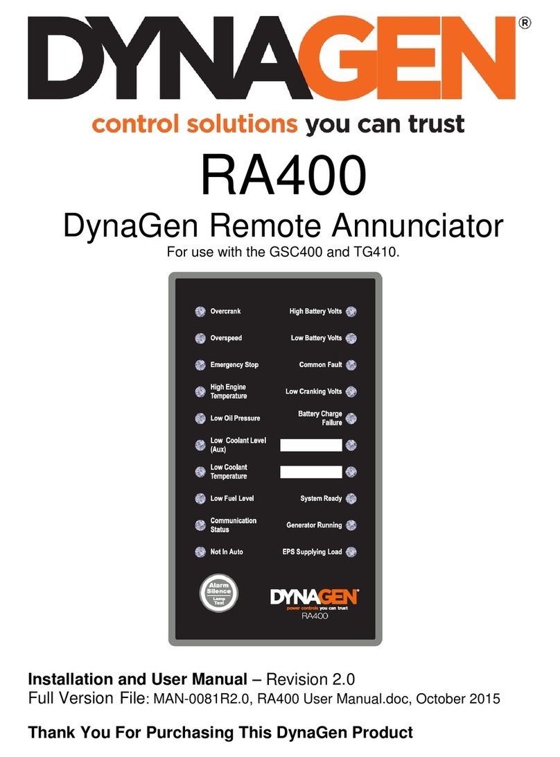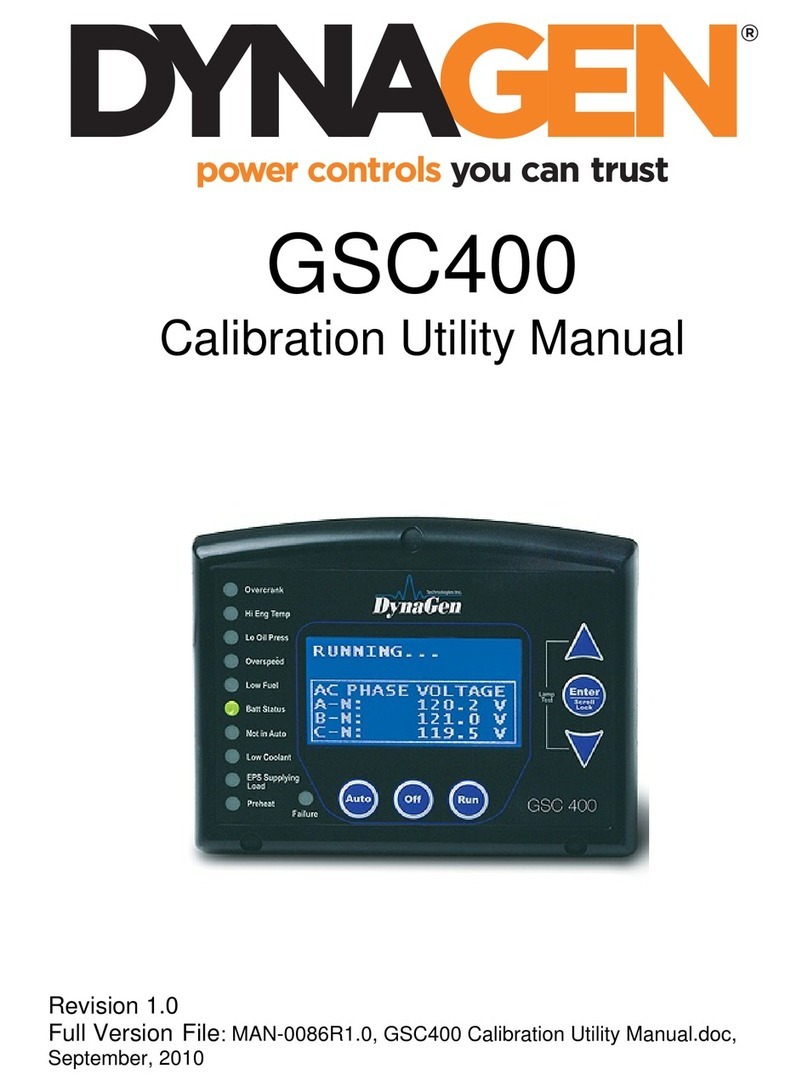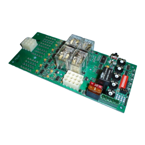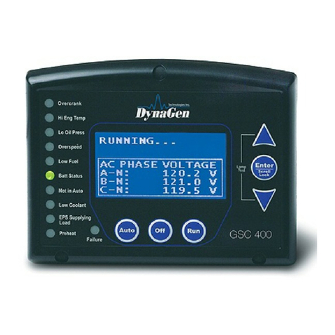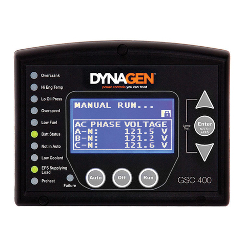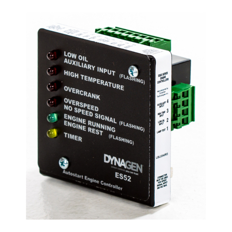
Operating & Installation Manual for the ES52 Engine Controller
2
LIMITED WARRANTY POLICY: DynaGen Technologies Inc. hereafter known as the Seller warrants
articles sold hereunder to be free from defects in material and workmanship. These express warranties are
the sole warranties of the Seller and any other warranties, expressed, implied in law, or implied in fact,
are hereby specifically excluded. The Seller’s sole obligation under its warranty shall be, at its option, to
either issue a credit, or repair or replace any article or part thereof, which is proved to be defective. Any
adjustment of credits will be based upon original billing prices. All warranties shall expire 5 years from
date of shipment by the Seller, unless otherwise specified in other written communications from the
Seller. Any replacement product provided to the Buyer shall be subject to the original warranty period,
which will expire 5 years from the date of shipment of the original article. Notice of claimed breach of
warranty must be given within the applicable period. No allowances shall be made to the Buyer for any
transportation, duties, brokerage fees, labor costs, or parts adjustments or repairs, or any other work,
unless said charges are authorized in writing, in advance, by the Seller. The Seller shall, in no event, be
liable for special or consequential damages or for loss of profit. The warranty shall not extend to any
articles or parts thereof which have been installed, used, or serviced, other than in conformity with the
Seller’s application specifications, manuals, bulletins, or instructions, or, if none, shall have been
subjected to improper installation, misuse, or neglect. The warranties shall not apply to any materials or
parts thereof, furnished by the Buyer, or acquired from others at the Buyer’s request and/or to the Buyer’s
specifications or designs. The foregoing limitations on the Seller’s liability in the event of breach of
warranty shall also be the absolute limit of the Seller’s liability in the event of the Seller’s negligence in
manufacture, installation, service, or otherwise, with regard to the articles covered hereby, and upon the
expiration of the stated warranty period, all such liabilities shall terminate.
RETURNS: If any article is claimed to be defective in material or workmanship, the Seller, upon notice
promptly given, will issue a written return material authorization (RMA) with shipping instructions for
return to the Seller. All returns must be accompanied by an RMA number or shipments will not be
accepted by the Seller. Articles which are returned as defective, but are found to meet the specifications
agreed upon, will be subject to a re-testing charge. At the discretion of the Seller, unused and undamaged
Standard Products may, under certain circumstances, be accepted back for credit or exchange. A
restocking charge of 15% will apply. Unused custom designed products will not be accepted back for
credit or exchange.
For questions or comments regarding this product, contact:
DynaGen Technologies Inc.
Phone (902) 562 0133
Fax: (902) 567 0633
Web Site: www.dynagen.ca
