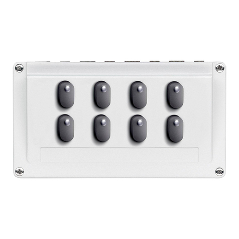
marklin 72760 User manual

Signal-Schaltpult
Signal Control Box
Pupitre de commande pour signaux
Seinschakelbord
Pupitre de conmutación de señales
Quadro di comando per segnali
Signal-ställpult
Signal-styrekort
72760

2
NL
F
GB
D
Sicherheitshinweise 4
Wichtige Hinweise 4
Anschluss 4
Signal anschließen 6
Signal schalten 6
Funktionsstörungen 7
Safety Notes 8
Important Notes 8
Connecting 8
Connecting Signals 10
Controlling Signals 10
Trouble Running 11
Remarques sur la sécurité 12
Information importante 12
Branchement 12
Raccordement des signaux 14
Commutation des signaux 14
Dysfonctionnements 15
Veiligheidsvoorschriften 16
Belangrijke aanwijzing 16
Aansluiting 16
Signaal aansluiten 18
Signaal schakelen 18
Storingen 19

3
DK
S
Aviso de seguridad 20
Notas importantes 20
Conexión 20
Conexión de la señal 22
Maniobra de señales 22
Anomalías funcionales 23
Avvertenze per la sicurezza 24
Avvertenze importanti 24
Connessioni 24
Collegamento del segnale 26
Commutazione del segnale 26
Difetti nel funzionamento 27
Säkerhetsanvisningar 28
Viktig information 28
Anslutning 28
Anslutning av signal 30
Manövrering av signaler 30
Funktionsstörningar 31
Sikkerhedshenvisninger 32
Vigtige bemærkninger 32
Tilslutning 32
Tilslutning af signal 34
Signal skiftes 34
Funktionsstörningar 35

4
Sicherheitshinweise
Lesen Sie die Bedienungsanleitung vor der ersten Inbetrieb-
nahme aufmerksam durch.
• ACHTUNG! Erstickungsgefahr wegen abbrech- und
verschluckbarer Kleinteile.
• DasProduktdarfnuringeschlossenenRäumenverwen-
det werden.
• LagernSiedasProduktnichtunterdirekterSonnenein-
strahlung, starken Temperaturschwankungen oder hoher
Luftfeuchtigkeit.
Wichtige Hinweise
• DieBedienungsanleitungistBestandteildesProduktes
und muss deshalb aufbewahrt sowie bei Weitergabe des
Produktesmitgegebenwerden.
• DasProduktdarfnurinVerbindungmitSchaltnetzteil
66361/66365 verwendet werden.
• Esdürfen nur die Stellpulte 72760 miteinander verbunden
werden. Zur Verlängerung kann das Kabel 71054 verwen-
det werden. Eine Verbindung mit anderen Stellpulten ist
nicht zulässig (Abb. 2)
• Gewährleistung und Garantie gemäß der beiliegenden
Garantieurkunde.
• Entsorgung:www.maerklin.com/en/imprint.html
Anschluss
Um Beschädigungen während des Aufbaus zu vermeiden,
das Schaltnetzteil vom Haushaltsstromnetz trennen. Erst
nach Fertigstellung aller Verkabelungen das Schaltnetzteil
wieder in die Steckdose stecken.
• DasbeiliegendeKabelmitder4-poligeBuchse 1(links
oder rechts) einstecken (siehe folgende Abb.1).
• DanachdasSchaltnetzteilindieBuchse 2einstecken
(siehe folgende Abb.1).
• Signalanschlußkabelrot/braungegendasdemStellpult
beiliegende rot/braune Anschlußkabel tauschen und mit
dem Stellpult 72760 verbinden (Abb.3). Die Reihenfolge
des Anschlußes ist frei wählbar, maßgebend ist die
Adessierung und damit die Zuordnung zum Schalter.
• Adressenfx(MM)1-4.
Werkseinstellungen der Signale können mit der
Central Station 2 verändert werden.
!DiebeiliegendenKabeldürfennichtverändertwerden.

5
Abb.1
Abb.2
66361/66365
72760
66361/66365 72760 72752/72751
nicht zulässig
1
1
2
2
3
72760
Anschluss
71054

6
Ist die Leuchtdiode erloschen, zeigt das Signal „Halt“.
Weitere mögliche Signalbilder und ihre Zuordnung
Mehrbegriffige Signale können nur einem Stellpult zugeord-
net werden.
Es werden 2 Tasten (Adressen) benötigt. Das Signal vergibt
nach dem Einstellen der Grundadresse selbständig die
Folgeadresse. Folgende Tastenkombinationen (Adressen) sind
möglich, 1 + 2, 2 + 3 oder 3 + 4.
Signal anschließen
Die 2-polige Buchse des Signales (rot/braun) auf den 2-po-
ligenKontaktanderRückseitedesSchaltpulteseinstecken.
Signal schalten
DurchDrückenderTastewirddasSignalentsprechend
geschaltet.BrenntdiegrüneLeuchtdiodeanderTastedes
Schaltpultes, zeigt das Signal „Fahrt“.
Signalbild
Signalbild
Anschluß frei wählbar.
Zuordnung erfolgt automatisch
zur Taste und Adresse.
Beispiel
(Abb.3)
Signalbild
Signalbild

7
Sind alle Funktionen in Ordnung, kann das Schaltpult mit
beiliegendem Etikett beklebt und anschließend beschriftet
werden.
Das Schaltpult kann bei stationärem Aufbau mit den
Schrauben E786130 (gehört nicht zum Lieferumfang) befes-
tigt werden.
Funktionsstörungen
IstamSignalkeinLichtzusehen,prüfenSiebitte:
• IstdasNetzgerätindieSteckdoseundindasStellpult-
eingesteckt? Gegebenenfalls einstecken.
• SindalleVerbindungskabelrichtigeingesteckt?Gegebe-
nenfallsdieSteckerfestdrücken.
• IsteinVerbindungskabelbeschädigt?Beschädigtes
Kabel austauschen.
Ausfahrsignal 4-begriffig, 2 Tasten (Adressen)
Signalbild

8
Safety Notes
Make sure you read the following safety notes before using
this Märklin product for the first time.
•
IMPORTANT! Danger of choking due to detachable small
parts that may be swallowed
.
• Thisproductmayonlybeusedindoors.
• Donotstorethisproductindirectsunlightorareaswith
extreme swings in temperature or high humidity.
Important Notes
• Theinstructionsforuseareacomponentpartofthe
signal control box and must therefore be kept in a safe
place as well as transferred along with the signal control
box to third parties.
• Thisproductmayonlybeusedinconjunctionwiththe
66361/66365 switched mode power packs.
• Only the 72760 control boxes may be connected with
each other. The 71054 cable can be used to lengthen
the distance between control boxes. Connecting these
control boxes to other control boxes is not permissible
(see Figure 2).
• The warranty card included with this product specifies
the warranty conditions.
• Disposing:www.maerklin.com/en/imprint.html
Connecting
Unplug the switched mode power pack from the household
current in order to prevent damage during setup. Do not plug
the switched mode power pack in the wall outlet again until
you are finished with all of the wiring.
• Pluginthecablewiththe4-pinsocket 1(left or right) in-
cluded with the control box (see Figure 1 on the following
page).
• Afterthatplugtheswitchedmodepowerpackintothe
socket 2(see Figure 1 on the following page).
• Exchangethered/brownsignalconnectingcablewith
the red/brown connecting cable included with the control
box and connect to the 72760 control box (Fig.3). The se-
quence of the connections can be done any way desired.
The critical thing is the addresses set on the signals and
thereby their assignment to the control box.
• fx(MM)Addresses1-4.
Factory settings for the signals can be changed with the
Central Station 2.
!The cable that comes with the signal control box may not
be altered.

9
Fig. 1
Fig. 2
66361/66365
72760
66361/66365 72760 72752/72751
Not permitted
1
1
2
2
3
72760
Connections
71054

10
If the LED is off, the signal shows “Stop”.
Other Possible Signal Aspects and Their Assignment.
Multi-aspect signals can be assigned to only one control box.
Two (2) buttons (addresses) are required. After setting the
basic address, the signal assigns on its own the sequential
address. The following button combinations (addresses) are
possible, 1 + 2, 2 + 3, or 3 + 4.
Connecting Signals
Plugthe2-pinsocketonthesignal(red/brown)intothe2-pin
contact on the back of the control box.
Controlling Signals
The signal is controlled by pressing on the button. If the
green LED is on at the button on the control box, the signal
will display “go“.
Signal aspect
Signal aspect
Connections as desired.
Assignment to the button and
address is automatic.
Example
Fig. 3
Signal aspect
Signal aspect

11
If everything is working properly, the label that comes with
the control box can be affixed to the latter and then be
lettered.
On a stationary setup, the control box can be mounted in
place with the E786130 screws (not included with the control
box).
Trouble Running
Ifthereisnolightvisibleonthesignal,checkthefollowing:
• Istheswitchedmodepowerpackpluggedintothewall
outlet and the Base Station? If not, plug it in.
• Arealloftheconnectingcablesproperlypluggedinto
their connections? If not, press on the plugs to make sure
they are all the way in the connections.
• Isaconnectingcabledamaged?Replaceanydamaged
cables.
Four (4) aspect exit signal, 2 buttons (addresses).
Signal aspect

12
Remarques sur la sécurité
Avant la première utilisation d’un produit Märklin, lisez impé-
rativementlesindicationsrelativesàlasécuritésuivantes:
• ATTENTION ! Danger d’étouffement à cause des petites
pièces cassables et avalables.
• Leproduitdoitêtreutiliséuniquementdansdespièces
fermées
• Leproduitnedoitpasêtreentreposédansunendroit
soumis à un ensoleillement direct, à de fortes variations
de température ou à une humidité importante.
Information importante
• Lanoticed‘utilisationfaitpartieintégranteduproduit;
elledoitdoncêtreconservéeet,lecaséchéant,transmi-
se avec le produit.
• Leproduitdoitêtreutiliséuniquementavecl‘alimentation
de coupure 66361/66365.
• Nereliezque les pupitres de commande 72760 entre eux.
Vous pouvez utiliser le câble 71054 comme rallonge. Vous
ne devez en aucun cas effectuer une connexion avec
d’autres pupitres de commande (cf.fig. 2).
• Garantielégaleetgarantiecontractuelleconformément
au certificat de garantie ci-joint.
• Elimination:www.maerklin.com/en/imprint.html
Branchement
Afin d’éviter toute détérioration durant l’installation, débran-
chez le convertisseur du secteur. Ne branchez le convertis-
seur qu’une fois le câblage terminé.
• Branchezlecâbleci-jointàlaprisequadripolaire 1
(droite ou gauche, cf. fig. 1 ci-après).
• Branchezensuitel‘alimentationdecoupureàlaprise 2
(cf. fig. 1 ci-après).
• Échangezlecâbledeconnexiondusignalrouge/marron
contre le câble de branchement rouge/marron du pupitre
de commande et branchez-le au pupitre de commande
72760(g.3).Vouspouvezchoisirl‘ordredubranche-
ment,seulcomptel‘adressageetdoncl‘affectationà
l‘interrupteur.
• Adressesfx(MM)1-4.
Vous pouvez modifier la configuration d’usine des interrup-
teurs avec la Central Station 2.
! Lecâblefourninedoitpasêtremodié.

13
Fig. 1
Fig. 2
66361/66365
72760
66361/66365 72760
72752/72751
Interdit
1
1
2
2
3
72760
Branchement
71054

14
Siladiodelumineuseestéteinte,lesignalindiquel’Arrêt..
Autres branchements possible des signaux et affectation.
Lessignauxàaspectsmultiplesnepeuventêtreaffectés
qu’à un seul pupitre de commande.
Il faut 2 touches (adresses). Après le réglage de l’adresse de
base, le signal envoie automatiquement l’adresse étendue.
Vous pouvez configurer les combinaisons de touches
suivantes (adresses), 1 + 2, 2 + 3 ou 3 + 4.
Raccordement des signaux
Branchez la prise bipolaire du signal (rouge/marron) au
contact bipolaire à l’arrière du pupitre de commande.
Commutation des signaux
Pourcommuterunsignal,appuyezsurlatouchecorrespon-
dante. La diode luminescente verte sur la touche du pupitre
indique le signal «Voie libre» .
Positiondesignal
Branchement au choix.
L’affectation se fait automa-
tiquement vers l’interrupteur et
l’adresse.
Exemple
Positiondesignal
Fig. 3
Positiondesignal
Positiondesignal

15
Si toutes les fonctions répondent correctement, les étiquet-
tesfourniespeuventêtrecolléessurlepupitreetmarquées
en conséquence.
Pourl’installationd’unpupitredecommutation«xe»,vous
pouvez utiliser les vis E786130 (non fournies).
Dysfonctionnements
Silalumièredusignalnes’allumepasvériezsi:
• Leblocd’alimentationestbienbranchésurlesecteuret
sur la station de base. Le cas échéant, branchez-le.
• Touslescâblesderaccordementsontcorrectement
branchés. Le cas échéant, enfoncez les connecteurs.
• Uncâblederaccordementestdétérioré.Lecaséchéant,
échangez le câble concerné.
Signal de sortie 4 aspects, 2 touches (adresses).
Positiondesignal

16
Veiligheidsvoorschriften
Lees zeker de volgende veiligheidsvoorschriften voordat
u een Märklinproduct voor het eerst gebruikt.
• OPGELET! Gevaar op verstikking door kleine delen die
kunnen afbreken of worden ingeslikt.
• Hetproductmaguitsluitendingeslotenruimtesworden
gebruikt.
• Bewaarhetproductnietopeenplaatsmetrechtstreeks
zonlicht, sterke temperatuurschommelingen of hoge
luchtvochtigheid.
Belangrijke aanwijzing
• Degebruiksaanwijzingmaaktdeeluitvanhetproducten
moet daarom bewaard worden en bij doorgave van het
product worden meegegeven.
• Hetproductmagalleenincombinatiemetdenetadapter
66361/66365 gebruikt worden.
• Alleen de schakelkastjes 72760 mogen met elkaar ver-
bonden worden. Voor het verlengen kan de verlengkabel
71054 gebruikt worden. Een verbinding met andere
schakelkastje is niet toegestaan (zie afb.2)
• Vrijwaringengarantieovereenkomstighetbijgevoegde
garantiebewijs.
• Afdanken:www.maerklin.com/en/imprint.html
Aansluiting
Om beschadigingen tijdens de montage te vermijden moet u
de schakelvoeding loskoppelen van het huishoudelijk circuit.
Steek pas nadat alle kabels in orde zijn de schakelvoeding
opnieuw in het stopcontact.
• Demeegeleverdekabelmetde4-poligestekkerbus 1
(links of rechts) insteken (zie de stappen op afb. 1).
• Daarnadenetadapterindestekkerbus 2steken (zie de
stappen op afb. 1)
• Deaansluitkabelvanhetseinrood/bruin,vervangendoor
de meegeleverde rood/bruine aansluitkabel en met het
schakelkastje 72760 verbinden (afb. 3). De volgorde van
de aansluiting is vrij te kiezen, maatgevend is de adresse-
ring en daarmee de toewijzing om te schakelen.
• Adresfx(MM)1-4
De fabrieksinstelling van de seinen kan met het
Central Station 2 gewijzigd worden.
!De bijgevoegde kabel mag niet worden veranderd.

17
afb. 1
afb. 2
66361/66365
72760
66361/66365 72760
72752/72751
Niet toegestaan
1
1
2
2
3
72760
Aansluiting
71054

18
Als de LED gedoofd is toont het sein “Stop”.
Andere seinbeelden en hun toewijzing
Meerstanden seinen kunnen maar aan één schakelkastje
toegewezen worden
Er zijn 2 toetsen (adressen) nodig. Het sein geeft na het in-
stellen zelf het volg-adres. De volgende toetsencombinaties
zijn mogelijk, 1+2, 2+3 of 3+4.
Signaal aansluiten
De 2-ploige stekkerbus van het sein (rood/bruin) op het 2 po-
lige contact op de achterzijde van het schakelkastje steken.
Signaal schakelen
Door op de knop te drukken, wordt het signaal overeen-
komstig geschakeld. Als de groene lichtdiode aan de knop
van de schakeltafel brandt, geeft die het signaal “rijden“.
Seinbeelden
Seinbeelden
Aansluiting vrij kiesbaar.
Toewijzing volgt automatisch
naar toets en adres.
Voorbeeld
afb. 3
Seinbeelden
Seinbeelden

19
Als alle functies in orde zijn, dan kan het bijgevoegde etiket
op de schakeltafel worden gekleefd en onmiddellijk worden
beschreven.
De schakeltafel kan bij stationaire montage met de schroe-
ven E786130 (niet in de levering) worden bevestigd.
Storingen
Alsergeenlichttezienisophetsignaal,controleerdan:
• Isdevoedingingestokeninhetstopcontacteninhet
basisstation? Indien nodig insteken.
• Zijnalleverbindingskabelscorrectingestoken?
Indien nodig de stekkers steviger aandrukken.
• Isereenverbindingskabelbeschadigd?
Beschadigde kabel vervangen.
Uitrij sein met 4 standen, 2 toetsen (adressen).
Seinbeelden

20
Aviso de seguridad
Antes de utilizar por primera vez un producto de Märklin,
siempre lea las siguientes advertencias de seguridad.
• ¡ATENCIÓN!Peligrodeasxiaacausadepiezaspeque-
ñas que pueden romperse y tragarse.
• Estápermitidoutilizarelproductoúnicamenteenrecintos
cerrados.
• Noalmaceneelproductobajolaradiaciónsolardirecta,
en lugares con fuertes oscilaciones de temperatura o con
una elevada humedad del aire.
Notas importantes
• Lasinstruccionesdeempleoformanparteíntegradel
producto y, por este motivo, deben conservarse y deben
entregarse junto con el producto en el caso de reventa
del mismo.
• Estápermitidoutilizarelproductoúnicamenteen
combinación con la fuente de alimentación conmutada
66361/66365.
• Estápermitidointerconectar entre sí únicamente los
pupitresdemando72760.Paraprolongaciónsepuede
utilizar el cable 71054. No está permitida la interconexión
con otros pupitres de mando (Fig. 2).
• Responsabilidadygarantíaconformealdocumentode
garantía que se adjunta.
• Eliminación:www.maerklin.com/en/imprint.html
Conexión
Paraevitardañosduranteelmontaje,aislarlafuentede
alimentación conmutada de la red eléctrica doméstica. No
volver a enchufar la fuente de alimentación conmutada en
el enchufe hasta después de haber terminado todos los
cableados.
• Enchufarelcableconhembrillade4polos 1que se ad-
junta y las hembrillas para conectores tipo jack (izquierda
o derecha) (véase Fig. 1 siguiente).
• Acontinuación,enchufarlafuentedealimentación
conmutada 2en la hembrilla (véase Fig. 1 siguiente).
• Sustituirelcabledeconexióndelaseñalrojo/marrón
por el cable de conexión rojo/marrón que se adjunta al
pupitre de mando y conectarlo al pupitre de mando 72760
(Fig. 3). El orden secuencial de conexión puede elegirse
libremente, lo que importa es el direccionamiento y, por
tanto, la asignación al interruptor.
• Direccionesfx(MM)1-4.
Losajustesdefábricadelasseñalessepuedenmodicar
con la Central Station 2.
! Noestápermitidomodicarelcableadjunto.
Other manuals for 72760
1
Table of contents
Languages:
Other marklin Controllers manuals

marklin
marklin Central Station 3 User manual

marklin
marklin zu 29410 User manual

marklin
marklin 67014 User manual

marklin
marklin 66191 User manual

marklin
marklin Central Station Series User manual

marklin
marklin 72752 User manual

marklin
marklin Central Station Series User manual

marklin
marklin Central Station 3 User manual

marklin
marklin Central Station User manual

marklin
marklin Central Station 3 60216 Instruction Manual