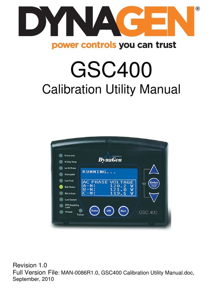
DynaGen GSC200 User manual

Installation and User Manual for the GSC200 Controller
Full Version
File: GSC200_R1_1doc
8/12/2008
GSC200
Auto Start Engine & Transfer Switch
Controller

Operating & Installation Manual for the GSC200 Controller
2
LIMITED WARRANTY POLICY: DynaGen Technologies Inc. hereafter known as the Seller warrants
articles sold hereunder to be free from defects in material and workmanship. These express warranties are the
sole warranties of the Seller and any other warranties, expressed, implied in law, or implied in fact, are hereby
specifically excluded. The Seller’s sole obligation under its warranty shall be, at its option, to either issue a
credit, or repair or replace any article or part thereof, which is proved to be defective. Any adjustment of credits
will be based upon original billing prices. All warranties shall expire 5 years from date of shipment by the
Seller, unless otherwise specified in other written communications from the Seller. Any replacement product
provided to the Buyer shall be subject to the original warranty period, which will expire 5 years from the date of
shipment of the original article. Notice of claimed breach of warranty must be given within the applicable
period. No allowances shall be made to the Buyer for any transportation, duties, brokerage fees, labor costs, or
parts adjustments or repairs, or any other work, unless said charges are authorized in writing, in advance, by the
Seller. The Seller shall, in no event, be liable for special or consequential damages or for loss of profit. The
warranty shall not extend to any articles or parts thereof which have been installed, used, or serviced, other than
in conformity with the Seller’s application specifications, manuals, bulletins, or instructions, or, if none, shall
have been subjected to improper installation, misuse, or neglect. The warranties shall not apply to any materials
or parts thereof, furnished by the Buyer, or acquired from others at the Buyer’s request and/or to the Buyer’s
specifications or designs. The foregoing limitations on the Seller’s liability in the event of breach of warranty
shall also be the absolute limit of the Seller’s liability in the event of the Seller’s negligence in manufacture,
installation, service, or otherwise, with regard to the articles covered hereby, and upon the expiration of the
stated warranty period, all such liabilities shall terminate.
RETURNS: If any article is claimed to be defective in material or workmanship, the Seller, upon notice
promptly given, will issue a written return material authorization (RMA) with shipping instructions for return to
the Seller. All returns must be accompanied by an RMA number or shipments will not be accepted by the
Seller. Articles which are returned as defective, but are found to meet the specifications agreed upon, will be
subject to a re-testing charge. At the discretion of the Seller, unused and undamaged Standard Products may,
under certain circumstances, be accepted back for credit or exchange. A restocking charge of 15% will apply.
Unused custom designed products will not be accepted back for credit or exchange.
For questions or comments regarding this product, contact:
DynaGen Technologies Inc.
Phone (902) 562 0133
Fax: (902) 567 0633
WEB SITE: www.dynagen.ca
Operating & Installation Manual for the GSC200 Controller
3
SPECIFICATIONS FOR THE GSC200
Operating Voltage: 7 to 30VDC continuous
Zero volts operation for 100mS (assumes supply was 12VDC before
initiating starting)
Operating Temperature: -40 ºC to +85 ºC (LCD Display operates from to -16 ºC to 70 ºC)
Front Panel Indications
-High intensity LED’s with regulated brightness
LCD Display:
-LCD display for hour meter.
Adjustments
Warm-up: 0 - 200 seconds (After Failure Bypass Feature)
Cool-Down: 0 - 300 seconds (in 5 second increments)
Crank Disconnect: 12 to 140Hz
Overspeed: 40 – 200Hz
Underspeed: 40 – 200Hz
Crank Rest: 4 - 32 seconds (GREEN Engine Run LED will flash during Crank Rest)
Delay on Start: 0 – 59 seconds (GREEN Engine Run LED will flash during Delay on Start)
Crank Tries: 1 to 10
Failure Bypass: 10 – 55 seconds
Low Battery Indication: 7 – 35 VDC

Operating & Installation Manual for the GSC200 Controller
4
Timer adjustments:
Preheat: 0 - 255 seconds
Inputs
Speed Sensing:
-Generator Output Speed Sensing
-Maximum Input Voltage: 300VAC RMS
-Minimum Input Voltage: 0.7VAC RMS Generator Output Sensing
-60Hz Rejection Filter Included
-Loss of Speed Signal Included
Failure Inputs:
Oil Pressure
Coolant Temperature
2 Auxiliary Inputs
-Programmable for switch configuration NO or NC

Operating & Installation Manual for the GSC200 Controller
5
Protection:
-Reverse polarity protected
-Inputs are electrostatic discharge protected
-Maximum power supply surge before damage: 1500V for 250us
Outputs:
-All outputs switched to +battery (sourcing)
-2 Auxilliary Outputs:User configurable to one of 6 different options through software.
Connections
-Removable terminal blocks for input and output connections
Programming
-Windows based software interface utilizing the parallel port of your PC
-Needs no power to program using the PC Interface – uses power from parallel port of PC
-Specifications May Change Without Notification

Operating & Installation Manual for the GSC200 Controller
6
CONTROLLER OVERVIEW
General Failure Conditions
Low Battery Voltage Indication
Oil Pressure Input
High Temperature Input
Auxiliary Inputs
Hour Meter
Exerciser Function
Transfer Switch Controls
Utility Sensing
GENERAL FAILURE CONDITIONS
The following conditions can cause the GSC200 controller to shut down the Engine Generator system
unexpectedly.
Low Oil Pressure
Low Oil Failure is indicated by a steady on Red Low Oil pressure Led
High Coolant Temperature
High coolant temperature is indicated by a steady on RED High water temp LED
Overcrank
Overcrank failure is indicated by a steady on RED Overcrank LED
Overspeed
Overspeed failure is indicated by a steady on RED Overspeed LED
Loss of Speed Loss of speed signal is indicated by a steady on RED Loss of speed LED
Underspeed (If Enabled) Underspeed failure is indicated by a flashing RED Loss of speed LED
The Underspeed failure will only occur when the Underspeed condition remains
for more than 3 seconds.
LOW BATTERY VOLTAGE INDICATION
When the battery voltage drops below the user defined set point which can be programmed between 7 and
35VDC, the controller will illuminate the RED Low battery LED. The Low battery LED will be illuminated at
any time during OFF, AUTO and MANUAL modes. The Low battery indication will be disabled during failure
conditions.
LOW OIL INPUT
The Low Oil Input can be wired to either a NO (normally open) or NC (normally closed) switch (must be
correctly defined in software), the switch must be the type that closes to ground on failure. A failure delay can
be set in software to be certain that a failure has actually occurred; the delay can be set from 0.5 to 6 seconds in
0.5 second increments.
NOTE: The Low Oil Input failure is disabled during the failure bypass time.
HIGH TEMPERATURE INPUT

Operating & Installation Manual for the GSC200 Controller
7
The High Temperature Input can be wired to either a NO (normally open) or NC (normally closed) switch
(must be correctly defined in software), the switch must be the type that closes to ground on failure. A failure
delay can be set in software to be certain that a failure has actually occurred; the delay can be set from 0.5 to 6
seconds in 0.5 second increments.
NOTE: The High Temperature Input failure is disabled during the failure bypass time.
AUXILIARY INPUTS
There are two available Auxiliary Inputs which can be configured to either indicate a warning or generate a
failure in software. Both of these inputs can be wired to either a NO (normally open) or NC (normally closed)
switch (must be correctly defined in software), the switch must be the type that closes to ground on failure. A
failure delay can be set in software to be certain that a failure has actually occurred; the delay can be set from
0.5 to 6 seconds in 0.5 second increments.
NOTE: The Auxiliary Input failures are disabled during the failure bypass time.
HOUR METER
The hour meter displays the total accumulated generator run time. The display represents both hours and
minutes in the form 1234.5. The last digit on the hour meter will represent the time in 1/10’s of an hour. Please
note that the accumulated time displayed on the hour meter can not be reset.
EXERCISER FUNCTION
The exerciser function is programmable only through the front panel buttons. When the controller is first
powered up in Auto mode the Engine Run LED will flash to indicate that the Exerciser Function has not been
programmed if not already programmed. There are four intervals for the Exerciser selectable, once a week, once
every 2 weeks, once every 3 weeks and once every 4 weeks. At programming you must make note of the time
of the Exercise event as there is no way to retrieve that information once programming is complete. The
exercise cycle will last for 15 minutes plus the Cooldown period (if Cooldown enabled). The exercise cycle can
be interrupted by pressing the OFF button during the cycle, but the controller will resume the cycle if returned
to AUTO with time remaining in the cycle. How to program the Exerciser Function is explained later in the
manual.
TRANSFER SWITCH CONTROLS
The transfer switch controls can either be enabled or disabled in software. This allows the controller to be used
only as an Engine Controller. Please note that disabling the transfer switch controls does not disable or turn off
the Exerciser Function, it only disables the controller from starting the generator on a loss of utility.
UTILITY SENSING


Operating & Installation Manual for the GSC200 Controller
8
Utility sensing is measured from line to neutral and can accept voltages up to 300VAC. Single or three phase
sensing is user selectable in the GSC200 Configurator software.
LED INDICATIONS
Auto LED
High Temp Low Oil
Normal
Available
Transfer
to
Normal
Transfer
to
Emergency
Emergency
Available
OverCrank
Failure OverSpeed Loss Speed Low Batt Engine Run Aux
Auto Manual Off
LCD Display
AUTO LED: GREEN
The Auto LED will illuminate when the controller is placed into Auto.
HIGH TEMP LED: RED
The High Temp LED will illuminate when the High Temperature switch activates.
LOW OIL LED: RED
The Low Oil LED will illuminate when the Low Oil switch activates.
OVERCRANK LED: RED
The Overcrank LED will illuminate when the controller completes the selected amount of Crank tries without
successfully starting the Engine.
OVERSPEED LED: RED

Operating & Installation Manual for the GSC200 Controller
9
The Overspeed LED will illuminate when the Engine’s speed exceeds the value set by the user unless
Overspeed has been disabled in the software.
LOSS OF SPEED LED: RED
The Loss of Speed LED will illuminate when the speed signal drops to zero while the Engine is running.
LOW BATTERY LED: RED
The Low Battery LED will illuminate when the battery voltage drops below the value set by the user.
ENGINE RUN LED: GREEN
The Engine Run LED will illuminate when the engine starts and speed is detected by the controller.
AUXILIARY LED: RED
The Auxiliary LED has two purposes, first as an indication for Auxiliary Output 1, which can be set for one of
6 different functions by the user, and also as an indication for Auxiliary Output 2, which also can be set for one
of 6 different functions by the user. Both Auxiliary outputs can also be disabled in the software. When the
chosen function of Auxiliary Output 1 goes active the Auxiliary LED will flash as the indication. When the
chosen function of Auxiliary Output 2 goes active the Auxiliary LED will be steady on to indicate the failure.
NORMAL AVAILABLE LED: GREEN
The Normal Available LED will illuminate when the Voltage Sensing detects that the Utility is available.
TRANSFER TO NORMAL LED: GREEN
The Transfer to Normal LED will illuminate when the Transfer Switch is in the Normal position.
EMERGENCY AVAILABLE LED: RED
The Emergency Available LED will illuminate when the Voltage Sensing detects that the Generator source is
available.
TRANSFER TO EMERGENCY LED: RED
The Transfer to Emergency LED will illuminate when the Transfer Switch is in the Emergency position.
LCD DISPLAY:
The LCD display will show the total time that the generator has ran. This time is displayed when the controller
is in Engine run mode and can not be reset.

Operating & Installation Manual for the GSC200 Controller
10
PROGRAMMING THE GSC200
All of the features of the GSC200 that are user selectable or adjustable can be selected or adjusted by using the
GSC200 Configurator, the exception to this is the Exerciser Function which can only be programmed by the use
of the front panel buttons.
Programming the Exerciser Function
To enable the Exerciser Function of the GSC200, press and hold the Auto button, the Auto button must remain
held until the entire process is complete, after about 8 seconds the GREEN Engine Run LED will blink, after
the LED blinks press the Manual button the correct amount of times to set the interval between Exercise cycles.
The following chart shows the intervals that correspond to the number of times to press the Manual button.
Number of Button Presses Interval Time
1 Once Every 1 Week
2 Once Every 2 Weeks
3 Once Every 3 Weeks
4 Once Every 4 Weeks
NOTE: Please make note of the exact time that the programming of the Exerciser Function was done as there is
no way to retrieve this information from the controller once programming is complete. This will be the time that
the Exerciser will activate each time.
Once you complete the programming of the Exerciser the controller will immediately perform an Exerciser
cycle. The cycle begins with the GREEN Engine Run LED beginning to blink for 60 seconds, this is the alert
that an Exerciser cycle is about to begin. Once the alert time expires, the generator will start and if LOAD is
selected in the Configurator software the transfer switch will transfer to the generator source. If NO LOAD is
selected in the Configurator software then the generator will simply run for the duration of the cycle with no
transfer from the utility source. The duration of the Exerciser cycle is 15 Minutes plus the Cooldown period if
Cooldown is selected in the Configurator software.
Once the Exerciser cycle has begun you can interrupt the cycle by pushing the OFF button, however the time
will continue to count down so if the controller returns to AUTO the generator will start.
To disable the Exerciser Function, press and hold the Auto button, the Auto button must remain held until the
entire process is complete, after about 8 seconds the GREEN Engine Run LED will blink, after the LED blinks
press the OFF button and the Exerciser Function will be disabled.
NOTE: If at any time the battery is disconnected from the controller, the Exerciser Function will be reset to
disabled and the controller will again flash the indication that the Exerciser Function is not programmed when
the controller is put into Auto mode.
Table of contents
Other DynaGen Controllers manuals

DynaGen
DynaGen Tough Series User manual

DynaGen
DynaGen ES52 User manual

DynaGen
DynaGen Tough Series User manual

DynaGen
DynaGen GSC400 Series Operating and maintenance manual

DynaGen
DynaGen GSC400 Series User manual

DynaGen
DynaGen RA400 User manual

DynaGen
DynaGen GSC400 Series Use and care manual

DynaGen
DynaGen Tough TG350AMF User manual

DynaGen
DynaGen ES52 User manual

DynaGen
DynaGen TG410 User manual