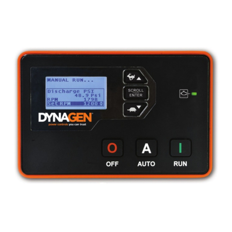
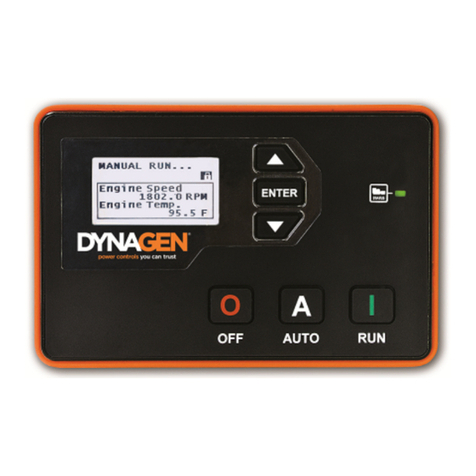
DynaGen Tough TG350AMF User manual

Manual Revision: 1.0
Software Revision: 1.2
Date Released: 7/24/2012
© 2012 DynaGen Technologies Inc.
TG350AMF User Manual

TOUGH Series User Manual
© 2012 DynaGen Technologies Inc.
Table of Contents
1Introduction
................................................................................................................................... 41.1 Specifications
................................................................................................................................... 51.2 Accessories
2Installation
................................................................................................................................... 82.1 Main I/O Starter Harness
................................................................................................................................... 92.2 Advanced I/O Harness
................................................................................................................................... 102.3 3-Phase AC Volts Harness
................................................................................................................................... 112.4 Magnetic Pickup / J1939 Interface Harness
................................................................................................................................... 122.5 Relay Pak (RP100)
................................................................................................................................... 132.6 AMF / ATS Wiring
................................................................................................................................... 142.7 Typical Wiring Diagram
3Using The Controller
................................................................................................................................... 173.1 Using the Menu System
................................................................................................................................... 183.2 Warnings, Failures and Events History
................................................................................................................................... 193.3 Starting, Stopping and Controller Modes
.......................................................................................................................................................... 20Emergency Stop and Failures3.3.1
4Configuration
................................................................................................................................... 234.1 Engine Logic
................................................................................................................................... 254.2 Switched Inputs
.......................................................................................................................................................... 27Voltage Select4.2.1
.......................................................................................................................................................... 28Configurable Inputs4.2.2
.......................................................................................................................................................... 28Start / Stop (Momentary Function)4.2.3
................................................................................................................................... 294.3 Switched Outputs
.......................................................................................................................................................... 30Pull and Hold Coil4.3.1
................................................................................................................................... 314.4 Sensors
.......................................................................................................................................................... 33Auxiliary Sensors4.4.1
.......................................................................................................................................................... 36Custom Sensor Tables4.4.2
.......................................................................................................................................................... 37Speed Sensing and Battery4.4.3
................................................................................................................................... 384.5 AC Monitoring
.......................................................................................................................................................... 39AMF / ATS4.5.1
................................................................................................................................... 414.6 Exerciser and Maintenance
................................................................................................................................... 424.7 CAN Bus (J1939)
.......................................................................................................................................................... 44Diagnostic Trouble Codes4.7.1
.......................................................................................................................................................... 45DM1 Messages4.7.2
.......................................................................................................................................................... 46DM2 Messages4.7.3
.......................................................................................................................................................... 47DTC Conversion Methods4.7.4
Introduction 3
© 2012 DynaGen Technologies Inc.TOUGH Series User Manual
1 Introduction
The TOUGH series controllers are designed to provide complete control, protection, AC volts metering,
and engine instrumentation for both standard and electronic engines. The module is easily configured
using either the front panel buttons or our PC Configurator software. TOUGH series controllers are ideally
suited for severe duty applications where reliability is critical such as mobile and stationary generators.
Features and Functions:
5 Year Warranty
SAE J1939 CANbus Protocol
RPM via J1939, Magnetic Pickup, or Generator
Speed control offset for electronic engines
Autostart on low battery and other sensors
Trim feature for AC voltage inputs and sensors
Maintenance counter
Exerciser Clock
100 Event Log
Conformally coated for protection against
moisture and contaminants
Gasket for water ingress protection IP65
Free PC Configurator Software
Fast and rugged installation clips
Passcode protected
Automatic shutdowns and warnings
Manual and remote start
Momentary start/stop inputs
Pre-heat and many configurable timers
Accepts common senders (VDO, Datcon,
Murphy, and more)
Custom senders configurable with PC software
Displays:
Oil Pressure
Engine Temperature
Fuel Level
Oil Level
Hour Meter
RPM
Real Time Clock
AC Volts and Hz
Battery Voltage
J1939 DTC codes with
custom text
2 Custom Sensors
FEATURE
INCLUDED
J1939 CANbus
Magnetic Pickup Input
100 Event Log
Clock / Exerciser
Generator Metering
3-Phase
Mains Metering (AMF + ATS)
3-Phase
Configurable Switched Inputs
5
Resistive Sensors
3
Universal Sensor (Resistive, 0-5V, 4-20mA)
1
User Configurable Switched Outputs (+Fuel and Crank)
4

Introduction 4
© 2012 DynaGen Technologies Inc.TOUGH Series User Manual
1.1 Specifications
Testing Specifications:
The TOUGH Series controllers were rigorously tested to ensure durability, reliability and functionality.
The following specifications are a brief summary of the standards to which the controller has been
tested. For complete details on the testing performed please contact DynaGen.
SPECIFICATION
RATING
Electrical Transients
SAE1113-11
Thermal Shock and Cycling
SAE1455
Vibration Profiles
SAE1455
Electric Static Discharge
SAE1113-13
Physical Specifications:
SPECIFICATION
RATING
Operating Temperature
-40 to +158°F (-40 to +70°C)
LCD Viewing Temperature
-4 to +158°F (-20 to +70°C )
Weight (With Relay Pak)
1.32lb (0.6kg)
Dimensions (With Relay Pak)
(Height x Width x Depth)
4.41" x 6.79" x 3.33"
11.20cm x 17.25cm x 8.46cm
Electrical Specifications:
SPECIFICATION
RATING
Operating Voltage
5.5 - 36VDC
Standby Current
50mA
Switched Inputs
+Battery, Ground, Open, Closed
Switched Outputs
+Battery @ 1A Max
Low Resistance Sensor (Ports B and C)
0 - 750Ω
High Resistance Sensors (Port A)
0 - 7,500Ω
Universal Sensor (Port D)
0 - 750Ω, 0 - 7,500Ω, 0 - 5VDC, 4 - 20mA
Magnetic Pickup
10 - 10,000Hz at 1 - 50VAC
AC Voltage (Line-To-Line)
50 - 575VAC True RMS
Accuracy: 1% Full Scale
Communications
SAE J1939 (Tier II, III, IV) and USB

Introduction 5
© 2012 DynaGen Technologies Inc.TOUGH Series User Manual
1.2 Accessories
The following items are available to be purchased from DynaGen to be used with the TOUGH Series
controllers.
ACCESSORY
PART NUMBER
DESCRIPTION
Relay Pak
RP100
Snap-on Relay Pak with 3 x 12V @ 40A relays
Enclosure (NMEA 1)
ENC0080
Steel enclosure with cutout and vibration mounts
Silicon Gasket
ENC0059
Replacement Silicon Gasket
Mounting Clip
ENC0068
Replacement Mounting Clip
12V Relays
RLY0053
Replacement 12V Relays
24V Relays
RLY0054
Replacement 24V Relays
USB Cable
ACC0084
Programming and firmware update cable
Temperature Sensor
ACC0027
Datcon 100-280C, 1/8”- 27 NPTF
Temperature Sensor
ACC0098
Datcon 100-280C, 3/8” – 18 NPTF
Temperature Sensor
ACC0099
Datcon 100-280C, 1/2” – 14 NPTF
Oil Pressure Sensor
ACC0108
S & W (2798) 100 PSI, 240 ohm, 1/8”- 27 NPTF
Pre-assembled Harnesses
The following DynaGen's harnesses are pre-assembled and sold separately. Each wire on the harness is
4 feet in length unless otherwise specified in the harness drawings.
HARNESS
PART NUMBER
DESCRIPTION
Main I/O Starter Harness
DWG1475
Battery, ground, 3 switched inputs, 3 switched
outputs, and 3 resistive sensors.
Main I/O Starter Harness for
Relay Pak
DWG1476
Battery, ground, 3 switched inputs, 3 resistive
sensors, and connections from the switched
outputs to the external Relay Pak connector.
Advanced I/O Harness
DWG1477
2 Switched Inputs, 3 Switched Outputs, and 1
Universal Sensor.
Magnetic Pickup / J1939
Interface Harness
DWG1478
J1939 and Magnetic Pickup
3-Phase AC Volts Harness
(Genset or Mains)
DWG1479
AC Voltage Sensing. Two of these harnesses are
required for genset and mains monitoring.
4 - 20mA
DWG1496
Required for universal sensor (Port D) to function
as a 4 - 20mA input.

Introduction 6
© 2012 DynaGen Technologies Inc.TOUGH Series User Manual
Custom Harness Component List
If DynaGen harnesses are not suitable for your application, custom harnesses can be created using the
following part list:
COMPONENT
PART NUMBER
NOTES
Molex 2x3 Connector
39-01-2060
Used with Relay Pak harness.
Molex 2x4 Connector
39-01-2080
Used with Advanced I/O Harness.
Molex 2x5 Connector
39-01-2100
Used with Magnetic Pickup / J1939 Interface
Harness.
Molex 2x7 Connector
39-01-2140
Used with Main I/O Starter Harness.
Molex Crimp Pins
39-00-0039
Used with all Molex connectors.
Molex Crimp Tool
63819-0900
Used with all Molex connectors.
Tyco 1x4 Connector
1-480702-0
Used with 3-Phase AC Volts Harness.
Tyco Crimp Pins
350536-1
Used with 3-Phase AC Volts Harness.
Tyco Crimp Tool
90546-1
Used with 3-Phase AC Volts Harness.
18 AWG Wire
N/A
Used with every harness.

Installation 7
© 2012 DynaGen Technologies Inc.TOUGH Series User Manual
2 Installation
Safety Precautions
Generator systems contain high voltage circuitry and precautions to protect against it should be taken.
Failing to power down and lock out equipment can cause damage, injury or death.
WARNING: Wiring of this controller should be performed by qualified electricians only.
The following general electrical safety precaution should be followed:
Do a thorough inspection of the area before performing any maintenance.
Keep fluids away from electrical equipment.
Unplug connectors by pulling on the plug and not the cord.
Use fuses where appropriate.
Ensure all equipment is properly grounded.
Provide support to wires to prevent stress on terminals.
Mounting the Controller
To ensure proper and safe operation, caution must be taken at the installation site to make sure it is free
from excessive moisture, fluctuating temperature, dust and corrosive materials. Choose a mounting
surface with the least amount of vibration and not more than 0.125" thick.
To mount the controller follow these instructions.
1) Choose a suitable mounting location based on the criteria above.
2) Create a rectangular cutout in the panel that is 3.9" high and 6.2" wide.
3) If applicable, snap the Relay Pak (RP100) to the back of the controller. Place one side of the
RP100s tabs into the slot on the back of the controller and without pushing on the relays, snap
the other tab into place.
4) Place the controller into the panel cutout so that the LCD screen and buttons are facing out.
5) Place the mounting clips into the designated slots on the top and bottom of the controller.
6) Tighten the screws on the clips until controller is snug against the panel. Do not over tighten, the
bottom of the screws should angle very slightly away from the controller.

Installation 8
© 2012 DynaGen Technologies Inc.TOUGH Series User Manual
2.1 Main I/O Starter Harness
The Main I/O Starter Harness (or equivalent) is required to provide power to the controller. It also has
inputs and outputs that can be interfaced to outside devices / components. There are 2 versions of this
harness offered:
1. Standard - This version does not have the pre-wired connections to an external connector that
plugs into the Relay Pak.
2. Relay Pak - This version has Ground and Switched Outputs A, B, and C wired to an external
connector that plugs into the Relay Pak.
TERMINAL
FUNCTION
DESCRIPTION
J4-1
+Battery
These connections connect battery power to the controller.
The second +Battery connection can be used to power
external devices of up to 1A.
J4-2
+Battery
J4-3
-Battery
These connections provide a ground return line from the
controller. The second -Battery connection can be tp
provide ground for external devices of up to 1A.
J4-4
-Battery
J4-5
Switched Input A
Switched inputs are configurable to detect battery voltage,
ground, closed, or open. See Switched Inputs for more
information.
J4-6
Switched Input B
J4-7
Switched Input C
J4-8
Switched Output A
Each switched output provides +Battery voltage when active
and can supply up to 1A of current.
Switched Output A is locked to Fuel Relay
Switched Output B is configurable.
Switched Output C is locked to Crank Relay.
J4-9
Switched Output C
J4-10
Switched Output B
J4-11
Sensor Ground
Provides ground for 2-wire sensors.
J4-12
Sensor Input A
High resistance sensor (0 - 7,500Ω)
J4-13
Sensor Input B
Low resistance sensor (0 - 750Ω)
J4-14
Sensor Input C
Low resistance sensor (0 - 750Ω)
Looking at rear of controller
25

Installation 9
© 2012 DynaGen Technologies Inc.TOUGH Series User Manual
2.2 Advanced I/O Harness
The Advanced I/O Harness is only required if the number of inputs and outputs on the Main I/O Starter
Harness are not sufficient to meet the requirements of your application.
TERMINAL
FUNCTION
DESCRIPTION
J3-1
Switched Input D
Switched inputs are configurable to detect battery voltage,
ground, closed, or open. See Switched Inputs for more
information.
J3-2
Switched Input E
J3-3
Switched Output D
Each switched output provides +Battery voltage when active
and can supply up to 1A of current. They can be
configurable to functions listed in Switched Outputs .
J3-4
Switched Output E
J3-5
Switched Output F
J3-6
No Connection
This terminal is currently not used.
J3-7
Sensor Ground
Provides ground for 2-wire sensors.
J3-8
Sensor Input D
(Universal Sensor Input)
Can be configured using the PC Configurator to sense low
resistance, high resistance, 0 - 5V, or 4 - 20mA. The 4-
20mA options requires harness DWG1496.
Looking at rear of controoller
Universal Sensor Input (Port D)
The Universal Sensor Input has the ability to sense low resistance, high resistance, 0 - 5V and 4 - 20mA
sensors. In order to configure this input you must use the PC Configurator. See for more information.
To use the sensor as 4 - 20mA it requires wiring harness DWG1496. The following directions describe
how to install the harness:
1. Place the crimp side of the 4 - 20mA wire into connector position J3-7.
2. Place Sensor Input D wire into the 'Run' channel of the Scotchlok connector.
3. Place the other side of the 4 - 20mA wire into the 'Stop' channel of the Scotchlok connector.
4. Drive the U-Contact down and latch the top cover.
25
29

Installation 10
© 2012 DynaGen Technologies Inc.TOUGH Series User Manual
2.3 3-Phase AC Volts Harness
The 3-Phase AC Volts Harness is used for AC metering of the generator and mains voltages. A second
harness is required if mains sensing is desired (AMF).
TERMINAL
FUNCTION
DESCRIPTION
J5-1
Generator Phase A
The controller can be configured in AC Monitoring to
accommodate various voltage configurations. See below for
more information.
J5-2
Generator Phase B
J5-3
Generator Phase C
J5-4
Generator Neutral
TERMINAL
FUNCTION
DESCRIPTION
J7-1
Mains Phase A
AMF versions only. The controller can be configured in AC
Monitoring to accommodate various voltage
configurations. See below for more information.
J7-2
Mains Phase B
J7-3
Mains Phase C
J7-4
Mains Neutral
Looking at rear of controller
Voltage Configurations
The controller can be configured in the settings for a variety of different voltages and setups. The
diagrams below indicate the configurations and the necessary wiring connections for each one.
NOTE: If using a 2-Wire Single configuration you must use Phase A terminal. If using 3-Wire
Single configuration you must use Phase A and B terminals.
38
38

Installation 11
© 2012 DynaGen Technologies Inc.TOUGH Series User Manual
2.4 Magnetic Pickup / J1939 Interface Harness
The Magnetic Pickup / J1939 Interface Harness is only required if you are using an electronic engine or
acquiring your speed signal from a magnetic pickup sensor.
TERMINAL
FUNCTION
DESCRIPTION
J6-4
CAN Bus High
CAN Bus (J1939) is used for electronic engines that have
an ECM.
J6-5
CAN Bus Low
J6-6
CAN Bus Shield
J6-7
Speed Input A
The speed sensing terminals are not sensitive to polarity.
Magnetic pickups, tachometers, or a flywheel alternator can
be used to provide signal. These inputs are not required if
AC voltage is being used. See Speed Sensing and Battery
for more information.
J6-8
Speed Input B
NOTE: Terminals J6-1, J6-2, J6-3, J6-9 and J6-10 are unused. These are left open for future
expansion.
Looking at rear of controller
CAN Bus (J1939) Wiring Considerations
CAN Bus (J1939) is for use with electronic engines. There are some special precautions that need to be
taken when wiring to the electronic control module (ECM).
If controller is not the last device on the bus, connect to the existing bus and ensure that there are
120Ω terminating resistors at each end of the bus.
If controller is the last device on the bus, you must install a 120Ω terminating resistor across the
CAN High and CAN Low lines as shown in the figure below.
If running the cable over a long distance, use Beldan 7895A cable or equivalent cable.
For the ECM to function, it must first receive power for a short time before cranking to allow it to boot. It
is common practice to use the fuel relay to turn the ECM on and off. There are two ways to configure
this:
The fuel relay is on during 'Preheat'. Increasing the 'Preheat' time in the Engine Logic menu
will allow longer time for the ECM to power up before cranking.
Turning on the 'Auto Power ECM' setting in the J1939 menu enables the fuel relay to be on when
controller is in Auto mode. This way the ECM will be always be on except wen in OFF mode.
37
23

Installation 12
© 2012 DynaGen Technologies Inc.TOUGH Series User Manual
2.5 Relay Pak (RP100)
The Relay Pak (RP100) can be used to control DC devices. Be sure to select relays based on your
system voltage (12 or 24V). Listed below are the wiring connections and their functions.
TERMINAL
FUNCTION
DESCRIPTION
J1-2
J1-5
-Battery
This connection provides a ground return line from the RP100 to
the controller.
J1-6
J1-4
J1-3
J1-1
Relay A (Coil)
Relay B (Coil)
Relay C (Coil)
Relay D (Coil)
Activated by applying 12 / 24V to the terminal. These are
intended to be connection to switched outputs on the controller.
J2
J5
J4
J7
Relay A (Contact)
Relay B (Contact)
Relay C (Contact)
Relay D (Contact)
Connect to high current auxiliary devices. Wire gauge is
dependent upon current requirements.
Pilot Duty Rating: 5.83A per relay
Resistive Rating: 10A per relay (40A Momentary)
J3
A/C Common
(Contact)
Relays A and C share a common contact point. Connect this
terminal to +Battery or -Battery. Wire gauge is dependent upon
amperage requirements.
J6
B/D Common
(Contact)
Relays B and D share a common contact point. Connect this
terminal to +Battery or -Battery. Wire gauge is dependent upon
amperage requirements.
The following is a sample wiring diagram using the RP100. Keep in mind that the wires from connector
J1 are connected to the controllers switched outputs and ground.

Installation 13
© 2012 DynaGen Technologies Inc.TOUGH Series User Manual
2.6 AMF / ATS Wiring
When wiring to a transfer switch there are two main items to take into account:
Wire the transfer switch so that it defaults to the mains position if the controller fails by using a
normally closed relay to the Mains coil.
Use limit switches (if applicable) to disengage the AC voltage to the coil when the switch is in that
position. This prevents the coil from burning out.
The following is an example wiring diagram for a transfer switch. Keep in mind that there are some items
omitted (fuses, connections to controller, etc.) and that not all configurations will be the same.

Installation 14
© 2012 DynaGen Technologies Inc.TOUGH Series User Manual
2.7 Typical Wiring Diagram

Using The Controller 15
© 2012 DynaGen Technologies Inc.TOUGH Series User Manual
3 Using The Controller
The controller is equipped with an LCD screen (A), the navigation buttons (B), LED lamps (C) and the
functional buttons (D). These components provide the means to interact with the controller.
LCD Screen (A)
The LCD Screen is the main source for providing information to an
operator. From the LCD screen you can view and navigate the status,
engine parameters, settings, and time.
Warnings and failures will appear on the LCD Screen and will be logged
into the Events History of the controller.
Navigation Buttons (B)
The Navigation Buttons are used to move throughout the menu system, change settings and view
parameters on the LCD screen.
SYMBOL
FUNCTION
DESCRIPTION
Up
Used for moving around in the menu, changing a settings
value, or changing the currently displayed parameter page.
Enter
Used for entering the menu system, accepting settings, or
locking the LCD screen when viewing parameters.
Down
Used for moving around in the menu, changing a settings
value, or changing the currently displayed parameter page.

Using The Controller 16
© 2012 DynaGen Technologies Inc.TOUGH Series User Manual
LED Indicators (C)
The LED indicators are used to display the current status of the system. Different versions of the
TOUGH series controllers have different LED combinations therefore some symbols may not appear on
your controller. The following table shows the meanings of each symbol and LED color.
SYMBOL
FUNCTION
LED STATUS
DESCRIPTION
Generator Status
Solid Green
Engine Running
Solid Amber
Warning
Solid Red
Failure
Mains Status
Solid Green
Mains Available
Solid Red
Mains Unavailable
Load
Symbol Only
Symbol Only
Switch Position
Solid Green
Switch Active
Functional Buttons (D)
The following table describes the function of the Functional Buttons. Keep in mind that some buttons
may have multiple purposes depending on the status of the controller.
SYMBOL
FUNCTION
DESCRIPTION
Off
Used for turning off the engine or exiting out of AUTO mode.
All automatic methods of starting the engine are disabled.
Auto
Places the controller in AUTO mode which allows it to start
or stop based on conditions (Exerciser, Low Battery
Recharge, Failure, Remote Start, Loss of Mains).
Run
Starts the engine manually and will continue to run until the
off button is pressed, emergency stop input is activated, or
a failure occurs.

Using The Controller 17
© 2012 DynaGen Technologies Inc.TOUGH Series User Manual
3.1 Using the Menu System
Switching Between Menus
Press the ENTER button to navigate into the configuration menu of the controller. If the controller is in
AUTO or RUNNING mode you must first enter OFF mode by pressing the OFF button.
NOTE: Entering the OFF mode while the generator is running will shut it down.
Use the UP and DOWN buttons located next to the LCD screen to
scroll through menus. The current position on the screen is indicated by
the HIGHLIGHTED TEXT. A scroll bar may be displayed on the right
hand side of the screen. This indicates the current position in the menu
and pressing the UP or DOWN buttons will reveal more options.
To move into the currently highlighted menu item you must press ENTER. If you wish to move to a
previous menu, scroll up and select 'Back' by pressing the ENTER button.
Changing a Setting
To change a setting on the controller you must first navigate to it. Once you have the setting you wish to
change highlighted, press enter to view the options menu for that setting.
There are generally 2 types of settings. One is a list setting that you
must scroll up and down to select the option that you want. The other
type is a numerical setting. To change this setting you must use the
up and down buttons to scroll to the value you want. To change the
value quickly, press and hold the directional arrow.
Once you have changed your setting to the desired value, you must
press the enter button to accept the change. Upon pressing enter a check mark will appear, press enter
again to return to the previous menu.
Viewing Engine Parameters
While the controller is in AUTO or RUNNING mode you can view the current status of the engine (fuel
level, engine temperature, etc). By default the controller will automatically scroll through the parameters
for you to view.
To manually change the parameters you are viewing, scroll to it using
the UP and DOWN buttons. You can lock the screen from scrolling
by pressing the ENTER button. Upon being locked a small icon of a
lock will appear in the top right corner. You can still manually scroll
through the parameters while the screen is locked.

Using The Controller 18
© 2012 DynaGen Technologies Inc.TOUGH Series User Manual
3.2 Warnings, Failures and Events History
Warnings and Failures
Warnings and failures occur when certain parameters (fuel level, oil pressure, etc.) are outside of
specified limits. These settings can be set using the front panel or the PC Configurator. All warnings and
failures are recorded in the Events History section of the menu.
Events History
Every time an event of significance occurs, the time and date as well as a description of the event is
placed as an entry in the Events History. Examples of events are: 'Successful Start', 'Over Speed
Warning' or 'Low Oil Failure.'
To view the Events History :
1. Place the controller in OFF mode.
2. Press enter to bring up the Main Menu and then select Events History.
3. Press the up or down buttons to browse through the events.
4. Press enter to exit out of the Events History.
From this menu you can scroll up to 150 events using the up and down arrows. Keep in mind the events
are recorded in order so Event 1 is the most recent event and Event 150 is the oldest event.
NOTE: If a new event is recorded and there are already 150 events in the history, the oldest
recorded event will be deleted.
Device Information
You can find out information about the controller by navigating to the 'Device Info.' menu. From inside this
menu you can see the following information.
FUNCTION
DESCRIPTION
About Controller
Gives the hardware version, software version and serial number.
Maintenance
Gives the amount of time remaining before maintenance is required.
If '----' is displayed maintenance is disabled. A negative number
indicates the amount of time since maintenance timer expired.

Using The Controller 19
© 2012 DynaGen Technologies Inc.TOUGH Series User Manual
3.3 Starting, Stopping and Controller Modes
Controller States
The following table contains the states the controller can be in and their descriptions.. Each mode has a
different purpose and changes the way the controller interacts with the engine logic, inputs, outputs and
sensors.
STATE
DESCRIPTION
Off
While in OFF state, the user can change settings through the menu
system. Automatic starting is disabled.
Auto
While in AUTO state, automatic starting is armed and certain engine
parameters are monitored.
Running
While in RUNNING state, the controller waits to be stopped and
monitors engine parameters.
Failure
The controller shuts down the engine and reason for failure is
displayed on screen.
Start and Stopping Methods
The controller can be started and stopped in a variety of different methods. The following section
briefly outlines these methods:
NOTE: The LCD backlight will turn off during the first 2 seconds of cranking to limit
voltage dip during cranking.
Manual Start and Stop
Manual starting and stopping of the generator can be done through the front panel buttons. Pressing
the RUN button will start the engine and pressing the OFF button will stop the engine.
NOTE: Cool down time is bypassed when engine is started manually.
Start / Stop Input
Starting and stopping can be completed through use of switched input 'Start / Stop.' If you do not
have the AMF version of the controller, this input can be used as a 'Remote Start' contact for
connecting to pre-existing Automatic Transfer Switch infrastructure or other switch.
Switched input 'Start / Stop' also has a feature that allows it to be used as a momentary input. See
Start / Stop (Momentary Function) for more information.
Momentary Inputs
Switched inputs 'Momentary Start' and 'Momentary Stop' can be used for starting and stopping of
the engine. Unlike other inputs, they only have to be activated for a short period of time to perform
their function.
28
Table of contents
Other DynaGen Controllers manuals

DynaGen
DynaGen GSC400 Series Use and care manual

DynaGen
DynaGen GSC200 User manual

DynaGen
DynaGen Tough Series User manual

DynaGen
DynaGen ES52 User manual

DynaGen
DynaGen GSC400 Series User manual

DynaGen
DynaGen TG410 User manual

DynaGen
DynaGen RA400 User manual

DynaGen
DynaGen VTSC100 User manual

DynaGen
DynaGen Tough Series User manual

DynaGen
DynaGen GSC400 Series Operating and maintenance manual