Dynamic Mounting Down and Out Mount Guide

Down and Out Mount, installation and assembly.
www.DynamicMounting.com 1
DOWN AND OUT MOUNT
Installation and Assembly
ATTENTION! It is important to study these instructions carefully. Read all the instruc-
tions before starting. Pay special attention to proper placement and adjustment. Fol-
lowing these instructions in sequence will save time and avoid problems.
SET UP AND INSTALLATION:
1. ATTACH HANGERS TO SCREEN
2. ADJUST COUNTER-WEIGHT STRENGTH
3. PLACE THE MOUNT
4. ATTACH THE MOUNT TO THE WALL
5. HANG THE TV ON THE MOUNT
6. FINE-TUNE THE COUNTERBALANCE
7. ADJUST THE TOP AND BOTTOM TILT
8. ATTACH RUBBER BUMPERS
9. ATTACH AND DRESS CABLES
10. HANG THE PAINTABLE WALL PLATES
SEE OUR INSTRUCTIONAL VIDEO at www.DynamicMounting.com/Install
Proper and safe installation of this product will require professional level tools
and experience; if you are not competent, engage the services of a professional.
ese instructions are intended as an overall guide, and may not cover all possible
circumstances.
e consumer is responsible for correct and secure mounting. Dynamic Mount-
ing is not responsible for any damage, injury, or death resulting from improper
mounting or use of the Down And Out Mount.
e Down And Out Mount is rated for a maximum load of 125 lbs. Do NOT
exceed.
e Down And Out Mount is only designed for use with at panel televisions.
For assistance, contact Dynamic Mounting at: Info1@DynamicMounting.com.
HEAT DAMAGE! Electrical equipment placed near a heat source is at risk of damage. Do not expose your electri-
cal equipment or television to undue heat. Take all necessary precautions when mounting equipment over or near a
replace. Dynamic Mounting takes no responsibility for damage from a replace or other heat source to the television,
the mount, or other accessories.
FIREPLACES! When mounting the Down And Out Mount over a replace with a mantel, do NOT install the Down
And Out Mount such that more than half of the TV can be moved below the mantel.
e DOWN AND OUT MOUNT, from Dynamic Mounting, oers an ecient
mounting solution for large at screen TVs. Primarily designed for use over
shelves or replaces, oering up to 32 inches of vertical travel and adjustable tilt.
WARNINGS!
CONTENTS:
SPECIFICATIONS
PACKAGE CONTENTS
REQUIRED TOOLS AND
EQUIPMENT
BEFORE YOU START
PLACEMENT
MAINTENANCE:
GENERAL MAINTENANCE
ADJUSTING ANY PLAY IN THE
COUNTERWEIGHT MECHANISM AND
REDUCING NOISE
APPENDICES
OPTIMAL PLACEMENT ABOVE A
SHELF
MINIMUM CLEARANCE OVER SHELF
WARRANTY

Down and Out Mount, installation and assembly.
www.DynamicMounting.com 2
• All Dynamic Mounting products are compatible with most at panel
and curved TV’s that weigh between 20 and 125 lbs.
• e allowable mounting hole pattern is 7.1in (190mm) to 27.2in
(692mm) wide, up to 22.3in (566mm) high.
• is includes VESA mounting hole patterns 200×100, 200×200,
300×200, 300×300, 400×300, 400×400, 500×300, 600×400 (Width x
Height, in mm).
• Product Dimensions: 29.0 x 23.6 x 4.4 in.
• Product Weight: 24 lbs.
• Tilt: 7º from vertical in top position. +/- 1º in out through bottom
positions.
SPECIFICATIONS
PACKAGE CONTENTS
Hangers x2
Paintable covers x2
Mount

Down and Out Mount, installation and assembly.
www.DynamicMounting.com 3
PACKAGE CONTENTS (continued)
• DOWN AND OUT MOUNT
• Hangers (x2) (With #10, 7/8 in. machine screws and wash-
ers preordained.)
• White paintable plastic wall covers (x2)
REQUIRED TOOLS AND EQUIPMENT
• 7/16 and 1/2 in. box or open ended wrenches
• 9/16 in. box wrench. (A ratcheting socket wrench with
extension is recommended.)
• 1/4 in. drill bit
• Power drill
• Tape measure
• Stud nder
• Level
• Phillips screwdrivers
Note: You will require assistance with liing heavy parts
and equipment.
Fasteners for mounting the television to the Hangers, including:
• M6 x 20 mm (.78in) long Phillips head machine screw (x4)
• M6 x 35 mm (1.38in) long Phillips head machine screw (x4)
• M8 x 20 mm (.78in) long Phillips head machine screw (x4)
• M8 x 35 mm (1.38in) long Phillips head machine screw (x4)
• 1/4 tall plastic spacers; (4x) 1/8 in. tall plastic spacers (x8)
• Steel M6 washers (x4)
• 3/8in by 3 in. long lag-screws with washers (x4)
• Adhesive rubber-bumpers (x2)
• Zip ties (x4)
BAG 1.
BAG 1
BAG 2.
BAG 2

Down and Out Mount, installation and assembly.
www.DynamicMounting.com 4
ere are several factors to be considered for a proper and
safe placement of the Mount.
• Finding a comfortable viewing angle.
• Placing the TV and Mount, over a shelf or cabinet may
require careful calculation for an optimal result. (See
appendices)
• Placing the TV and Mount over a heat-source or re-
place, may risk damage to equipment or cables.
• We recommended that in the UP position the TV is
high enough to be out of reach of children.
• Verify the availability of the necessary power and signal.
• e Mount and TV must be somewhat centered on the
framing in the wall to be used. (In the case of a heavy TV
this is especially important.) See NOTE **
NOTE ** If suitable framing is not available, Dynamic
Mounting oers the Extra-Wall-Support bracket. For
more information go to: https://www.dynamicmounting.
com/product/extra-wall-support
• ink about correct and comfortable placement.
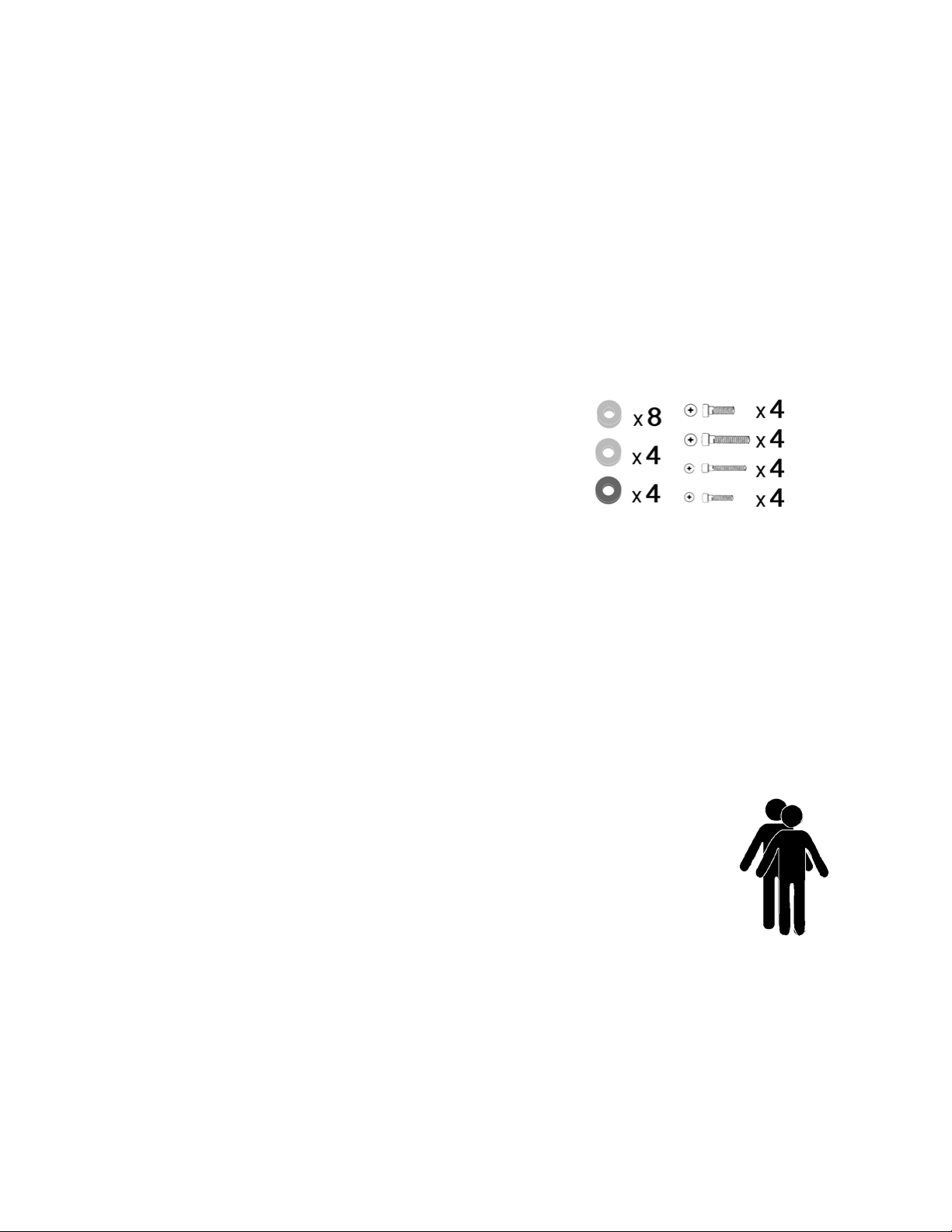
• Verify the box contents are complete and not damaged.
• Gather appropriate tools and any necessary help.
• Verify the position and size of the mounting points on
the screen to be mounted. (Screws of dierent lengths and
sizes are supplied.)
• Consult any product specic mounting information
supplied by the TV manufacturer.
• Determine the approximate weight of the screen.
(Down and Out Mount is designed for TVs of between 20 to
120 lbs. Knowing the weight will allow you to pre-adjust the
counter weight mechanism to an approximate value before
mounting.)
• Verify the substructure of the wall to be used. (It will be
necessary to locate the exact position of the studs, in a normal
wood-frame constructed wall.)
BEFORE YOU START
PLACEMENT
ese instructions, and the materials supplied, are intended for the installation of the Down
and Out Mount with standard wood-stud framed walls. e Down and Out Mount may be
attached to walls with other forms of construction, however additional hardware and profes-
sional help may be required.
In all cases, the wall to be used must be rated to support a total weight equivalent to four times
the combined weight of both the TV and the Mount.
WARNING!
Using a stud nder to locate the studs in a stand-
ard wood frame constructed wall.
The Extra-Wall-Support bracket is avail-
able at https://www.dynamicmounting.
com/product/extra-wall-support

Down and Out Mount, installation and assembly.
www.DynamicMounting.com 5
SET UP AND INSTALLATION.
a. Locate the mounting points on the back of the screen.
(It may be necessary to remove manufacturer’s plugs.)
b. Use M6 or M8 screws to attach hanger brackets to
back of screen. (Most screens will require either M6 or M8
depending on the size.)
c. Align the Hanger as close to top of screen as possible.
d. Use spacers and/or washers to ensure a rm connec-
tion. e Hangers must be tight to the back of the
screen. (A selection of washers, spacers, and screws of dier-
ent sizes are supplied.)
e. Use at least one plastic spacer between the Hanger and
T V.
f. Make a note of the distance between the bottom of the
Hanger and the bottom of the TV. is measurement
maybe needed later. (is will be length ‘A’ in gures
below.)
1. ATTACH HANGERS TO SCREEN
Align Hanger as close as pos-
sible to top of TV.
Take note of distance ‘A’
IMPORTANT!
Do not bottom out screws into the TV. Leave 1 or 2 turns
of free space by using a combination of washers and screws
of an appropriate length.
IMPORTANT!
A minimum screw depth of 1/2 in. is required for a safe
installation.
Minimum 1/2
in. screw depth
1 or 2 turns space Spacers
Washer

Down and Out Mount, installation and assembly.
www.DynamicMounting.com 6
For convenience, adjust the counter-weight value to match
the approximate weight of the screen, before attaching the
Mount to the wall.
a. From the factory, the counter-weight strength is set to
a maximum, 120 lbs.
b. For lighter screens, back o the adjustment screw.
c. Minimum counter-weight strength is 15 lbs
d. Setting the counter-weight in the middle (as shown)
will correspond to a working position for a 50 lbs
screen. It will be necessary to ne-tune this setting
aer the installation is complete.
2. ADJUST COUNTER-WEIGHT STRENGTH
NOTE When in the UP position, the Mount can be LOCKED into position by gently pushing
in on the bottom of the TV, and UNLOCKED by pulling out on the bottom of the TV. Out of
the box, the Mount will be unlocked but in the UP position.
Turn the bottom (9/16) nut to adjust the counter
weight force.
On a at wall, the Down and Out Mount gives a total
vertical movement of 32 inches. In the UP/LOCKED
position, the TV can be tilted forward for better viewing if
required.
It is recommended that in the UP position the TV is high
enough to be out of reach of children.
3. PLACE THE MOUNT
On a at wall, the Mount will give
up to 32 inches of vertical travel.
32 in.
Push in to lock posi-
tion
Note: Calculating the optimal mounting position over a
shelf depends on various possible factors including the
vertical height of the TV, and the width of the shelf. For
more detailed information see the appendix on page 12.

Down and Out Mount, installation and assembly.
www.DynamicMounting.com 7
45˚
3. PLACE THE MOUNT. continued
In most cases, the best mounting position over a shelf will be
achieved when the Mount Arm rests at a 45˙ angle in the down/
out position.
Over a shelf, cabinet, or mantel, it may be necessary to nd
the mounting position that will give the greatest top to bot-
tom movement of the TV.
a. Usually the greatest vertical movement over a shelf will
be achieved when the swivel arm is at a 45º angle in the
down position.
b. In this case, attach the base of the Mount at a height
above the shelf, approximately equal to the width of the
self itself.
NOTE: In all cases check that the TV will clear the shelf
when lowered. Make sure there is at least an appropriate
‘minimum clearance’.
(See “Minimum clearances” in the Appendixes.)
c. Attach the adhesive rubber bumpers to the underside of
the arm to protect the shelf from damage.
Bumper

Down and Out Mount, installation and assembly.
www.DynamicMounting.com 8
a. Locate the framing in the wall. (is may be done with
a stud nder.)
b. Use two adjacent studs with two bolts into each stud.
c. Mark the exact location of the studs that you intend to
use to secure the Mount. e center of gravity of the
TV and Mount should fall between the two studs.
IMPORTANT! For a safe installation, the screw bolts
must be screwed securely into the center of the studs.
It is very important to make sure you have located the
studs correctly. If in doubt, use a nail or spike to feel for
the studs through the sheetrock.
d. Hold the Mount in place on the wall at the height you
have chosen and over the studs you have marked.
e. Mark out four points for the bolts. All four points
must be centered on a stud.
f. Take away the Mount and drill one of the holes at the
correct position into a stud. Use a 1/4 in. drill for the
3/8 in. lag bolts with washers supplied. Drilling for
the bolt on the top right is usually easiest.
g. Now place the Mount back into place, and screw in the
rst bolt.
h. With a bubble-level: Level the bracket on the wall and
mark the exact position.
i. Drill the remaining three holes and secure with the
4. ATTACH THE MOUNT TO THE WALL
Drill one hole 1/4 in and screw in one bolt 3/8th
(top right for ease of access), before levelling
Mount.
With one bolt in place, level the Mount us-
ing a bubble level.
When levelled, mark and drill the remain-
ing 3 holes.
Screw in the remaining bolts with washers.

Down and Out Mount, installation and assembly.
www.DynamicMounting.com 9
5. HANG THE TV ON THE MOUNT
a. On the Hangers you will nd to two (#10, 7/8 in.) lock
screws with large washers.
b. Before liing the TV into place. Remove the two lock
screws and washers from the Hangers.
Note: You may need assistance to li the TV.
c. Li the TV and use the Hangers to hang the TV on
the Mount. (When you release the weight of the TV, the
Mount may gently lower into an OUT/DOWN position.)
d. For best operation, the TV should be centered on the
Mount.
e. Carefully lower the TV and the Mount to the OUT
position.
f. Secure the Hangers to the Mount with the 2 Lock
Screws and washers that were removed.
6. FINE-TUNE THE COUNTERBALANCE STRENGTH.
From the factory the Down and Out Mount comes adjusted
for the heaviest TV, (120 lbs.). Usually it is easiest to pre-
adjust to an approximate value before wall mounting. Aer
wall mounting, the adjustment may be ne-tuned.
a. Use a 9/16 wrench to turn the nut on the bottom of
the adjustment spline. (A ratcheting socket wrench with
extension is recommended.)
b. Turning counter-clockwise will increase the counter-
weight strength. It may take a couple of turns to use up
the slack in the mechanism before the counterbalance
block starts to move and the gas springs compress. (Or
expand, if you are reducing the counter balance force by
turning counter-clockwise).
c. Adjust the mechanism until the TV will rest in the
DOWN position and is as easy as possible to li into the
UP/LOCKED position.
Adjust the counter weight force by turning
the lower nut (9/16) on the counter weight
mechanism.
Lift the TV up and onto the mount. Carefully
allow the Mount to take the weight of the TV.
As it does it may drop forward.
Secure the Hangers to the Mount with the
screws that were removed.
Increases
force
Decreases
force

Down and Out Mount, installation and assembly.
www.DynamicMounting.com 10
8. ATTACH RUBBER BUMPERS
To adjust the tilt for the DOWN/OUT position:
a. With the arm in the DOWN/OUT position.
b. Loosen the lock-nut on the adjustment bolt.
c. Turn the adjustment bolt to the desired tilt. Make sure
both the le and right sides are set to the same posi-
tion.
d. Tighten the lock nuts on both sides.
Attach the adhesive rubber bumpers to the undersides of
the arms to protect a shelf or cabinet at the point of con-
tact.
9. ATTACH AND DRESS CABLES
You may use the zip ties as shown. Be careful not to place
the cables such that they may be pinched by the movement
of the arm.
e wall plates are supplied to improve the appearance of
the wall Mount when the TV is in the down position.
10. HANG THE PAINTABLE WALL PLATES
ere are separate adjustments for the tilt in the UP and
the DOWN/OUT position. Both the le and right side of
the arm must be adjusted separately. Make sure the set-
tings on the le and right sides match.
To adjust the tilt in the UP/LOCKED position:
a. With the arm in the OUT position. Loosen the lock nut
on the top tilt adjustment cam.
b. Turn the cam and tighten the lock nut. With the cam in
the lowest position you will have the most forward tilt.
c. Adjust both the le and right sides to the same setting.
d. If you nd that aer adjusting the top tilt the TV no
longer locks in the UP position reduce the amount of
top tilt and retry.
7. ADJUST THE TOP AND BOTTOM TILT
To adjust the tilt in the UP position. First loosen
lock-nut on the cam. Adjust cam position. Ad-
just both sides to the same setting.
To adjust tilt in the DOWN or OUT position,
loosen the lock-nut, before turning the adjusting
bolt. Adjust both sides to the same setting.
Use the zip ties to dress TV cables.
Cam
Lock-nut
Lock-nut
Adjustment

Down and Out Mount, installation and assembly.
www.DynamicMounting.com 11
Some noise from the mechanism, while
adjusting the TV position, is normal. How-
ever, it may be reduced by minimising any
play in the counterweight mechanism.
Reducing play in the adjustment mecha-
nism.
a. With the TV attached to the Mount
and in the UP position.
b. Turn the adjustment nut until all the
visible slack is taken up.
c. Test the adjustment by moving the TV
from top to bottom position.
MAINTENANCE
ADJUSTING ANY PLAY IN THE COUNTERWEIGHT MECHANISM AND REDUCING NOISE.
To ensure a long and optimal performance of the Down and Out Mount, follow
these simple steps:
• Move the Mount up and down at least twice a week, this keeps the seals in the
gas springs oiled.
• Lubricate all joints with a premium oil or grease at least every 3 months.
• Check all the bolts every 3 months to ensure none are coming loose or are
damaged.
GENERAL MAINTENANCE
Fixed nut Adjustment
To reduce play in the mechanism, hold the top
nut while turning the Adjustment nut to com-
press the spring washer.

Down and Out Mount, installation and assembly.
www.DynamicMounting.com 12
APPENDICES
OPTIMAL PLACEMENT ABOVE A SHELF
MINIMUM CLEARANCE OVER SHELF
Shelf Width/Depth
(Inches) 1 2 3 4 5 6 7 8 9 10 11 12 13 14 15 16
Minimum clearance for
TV in the up position.
(Inches)
1.25 1.25 1.5 1.75 2 2.25 2.25 2.75 3 3.25 3.75 4.2 5 5 5.75 6.75
In some cases in may be necessary to mount the TV as
low as possible over a shelf. Or the shelf may be more
than 12 inches deep.
It is important to allow enough space for the TV to
clear the shelf as it is lowered into the out position.
e correct mounting height (D)
will be equal to the “Minimum clearance” (see table
below),
plus the distance from the bottom of the Mount to the
bottom of the TV (A),
minus 3 in.
45˚
Shelf depth
Optimal mounting
height
To calculate the height over a shelf that will
give an exact 45˙angle to the arm in the
down position. Take the shelf depth and
subtract 1.5 in.
Minimum
clearance
Shelf depth
A = ‘bottom of Hanger’ to
‘bottom of TV ‘
A
D
3 in.
2 in.
D= Minimum Clearance + A- 3 in.

Down and Out Mount, installation and assembly.
www.DynamicMounting.com 13
WARRANTY.
Dynamic Mounting guarantees the Down And Out Mount to be free of defects for the product’s warranty
period of 5 years. e warranty period begins on the original date of shipping. e limited warranty is
intended only for the original purchaser. e warranty will be void if the Mount is modied in anyway
or not installed correctly. Including but not conned to overloading, abuse, or use for any purpose other
than specied in these directions. is mount is for indoor use only and the warranty will be voided if the
Mount is used outdoors. Dynamic Mounting is not liable for any damage or injury caused from the use of,
or the inability to use our Mount. To the maximum extent permitted by applicable law, Dynamic Mount-
ing disclaims any responsibility for incidental or consequential damages.
If you have any questions or problems, please contact us at:
info1@dynamicmounting.com
If you wish to receive help by phone, include a day time phone number, we
will contact you by phone as soon as we are able.
U.S. PATENT NO. 8,724,037 Dynamic Mounting LLC
Other manuals for Down and Out Mount
2
Table of contents
Other Dynamic Mounting TV Mount manuals