Dynamic Mounting Down and Out Mount User manual

- 1 –
Down And Out Mount Assembly & Installation Directions
ATTENTION!!
Mounting the Down And Out Mount correctly takes a lot of thought and a lot of planning. Please read the directions thoroughly and
plan out how the mount would be installed best for your use. Each Setup will be different and these directions cannot account for
every situation. Failure to do so may result in Damage, Injury, or Death. Dynamic Mounting is not responsible for any damage,
injury, or death resulting from improper mounting or use of the Down And Out Mount.
These instructions are only a guide and the consumer is responsible for correct and secure mounting. The person installing the mount
should be a competent person with experience mounting load bearing assemblies. For any questions or concerns, please contact
Dynamic Mounting at Info1@DynamicMounting.com.
The Down And Out Mount is rated for a max load of 120 LBS, Do NOT exceed.
The Down And Out Mount is designed for use with flat panel televisions. Do not use The Down And Out Mount with anything else.
The center of gravity of the flat panel television should not be any more than 4 inches off of the front of the Attach Arms.
WARNING!! Potential Heat Damage
Dynamic Mounting takes no responsibility for damage caused from the fireplace or other heating sources to the television, mount, or
other accessories. Damage could be done when the mount is down, out, or even up. It is up to the consumer to take the proper
precautions to avoid damage. Electrical equipment can overheat easier than expected. Dynamic Mounting recommends against having
fires in the fireplace whenever there is electrical equipment around.
Note!! Do NOT move more than half of your TV below a mantel located above a fireplace.
When mounting the Down And Out Mount over a fireplace with a mantel, do NOT install the
Down And Out Mount such that more than half of your TV can be moved below the top of the
mantel.
Specifications
Fits most Televisions 40 inches and larger. Check television weight and mounting hole pattern for compatibility with your
television.
Note for smaller televisions; the mount may be wider or taller than the television. If this is the case then the mount may be
visible in the up position. See Figure 1.
Handles televisions 20 to 120 lbs.
Allowable television mounting pattern: 6.6in (168mm) to 27.2in (692mm) wide, up to 19.8in (502mm) high. See Figure 1.
Product Dimensions: 29.0 x 23.6 x 4.4 inches. See Figure 1.
Product Weight: 24 pounds
Tilts 7 degrees to Vertical in top position
Vertical +/-1 degree in out through bottom positions

- 2 –
CAUTION: These wall mounting instructions and hardware are for mounting to wood
studs only. It is up to you to verify that the material supplied will work for your setup;
other materials may need to be purchased by you. For concrete, brick or other mounting
materials consult an expert.
Consult your television’s owner manual before mounting your television, it contains relevant
information.
Tools Needed
7/16 and 1/2 inch box or open ended wrench
9/16 inch box wrench, A ratcheting socket wrench with extension makes the job easier
1/4 inch Drill Bit
Drill
Tape Measure
Stud Finder
Level
Phillips Screwdrivers
A friend or 2, depending on how heavy your television is
Parts Included
1Down And Out Mount
2Attach Arms
2#10 x 7/8 inch long machine screw with washer for mounting the Attach Arms to the Down And Out Mount (These are
threaded into the Attach Arms, you need to remove before attaching TV to attach arms)
2 White Paintable Plastic Covers (Hang these over the Wall Plate to Cover arms, can be painted)
Various Items (All in One Bag)
43/8 inch by 3 inch long lag screw with washer
4Zip Ties
2Adhesive Rubber Bumpers
Fasteners for Mounting the Television to the Attach Arms (All in One Bag)
4M6 x 20 mm (.78in) long Phillips head machine screw
4M6 x 35 mm (1.38in) long Phillips head machine screw
4M8 x 20 mm (.78in) long Phillips head machine screw
4M8 x 35 mm (1.38in) long Phillips head machine screw
81/4 inch tall plastic spacers
41/8 inch tall plastic spacers
4Steel M6 washers

- 3 –
Figure 1
Mount Overall Size, Television Mounting Hole Pattern Range, Wall Mounting Hole Pattern Range
Note: Mount Only Comes with 2 television Mounting Arms, Not the 4 Shown
Figure 2 Side Views of Mount, Shown in the Top, Bottom, and All the Way Out Positions
Vertical in Up Position
Max Tilt (7 Degrees) in Up Position
Note: Vertical tolerance in the Out and Bottom Positions is +/-1 degree.
Top Position
Bottom Position
Out Position

- 4 –
Attaching Arms to Television
1. Use the Fasteners for Mounting the television to the Attach Arms for this. To get maximum clearance around shelves, the Attach
Arms should be mounted as high as possible on the television. If the Attach Arms are visible from the front, lower them until
they are hidden.
2. Your television will either have M6 or M8 threaded holes. If your television has M6 holes then use the M6 washers included
under the head of the M6 machine screw. When installing the arms you want as much screw engagement into the television as
possible without going too far and bottoming out the screw in the television. "Bottoming out" is when the screw cannot turn any
farther because the bottom of the screw is hitting something inside the television. If this occurs, DO NOT tighten anymore!
"Bottoming out" can cause damage to the television. Use a combination of spacers, washers, and screws to ensure you get the
most thread engagement without bottoming out. Every television is different; you may need to provide your own washers or
screws to get the ideal attachment. A minimum thread engagement of 8mm (.32in) into the television is required to ensure the
television is properly supported.
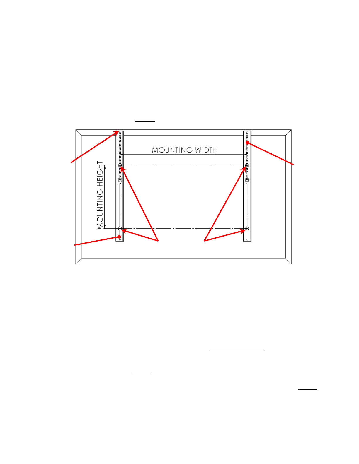
3. At minimum there should be a plastic washer between the Attach Arms and the television. The Attach Arms should not touch the
television directly in any location. Refer to Figure 3 to see how the Attach Arms should be attached.
Attach to TV
Attach Arm
Attach Arm
Arm as Close
to the Top of
the TV as
Possible
Figure 3 Attach Arms Mounted to Television
Mounting To Wall
4. The mount is designed to attach to standard 2in x 4in or larger wall studs spaced 16in apart. If the wall isn’t sturdy enough then
more support will need to be added, consult an expert.
5. The mount must be securely fastened to a structure that can support 4 times the total weight of the television and mount.
Dynamic Mounting assumes no responsibility for damage from an improperly installed mount.
6. The television should be centered on the mount as much as possible. If not the television will sag to one side. The heavier the TV
and the more off center, the more unlevel the TV will be through its range of motion. If your stud placement doesn’t allow for the
TV to be centered, the Extra Wall Supports (purchased separately) will give more side to side adjustment.
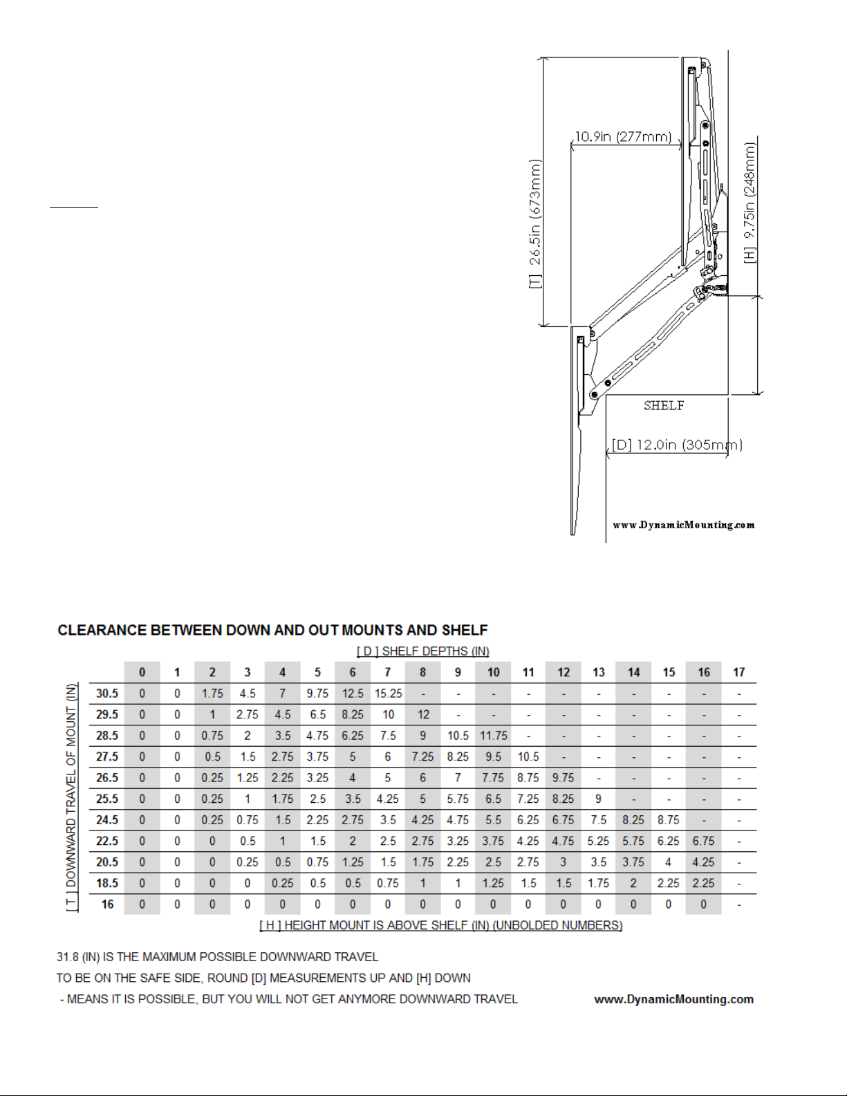
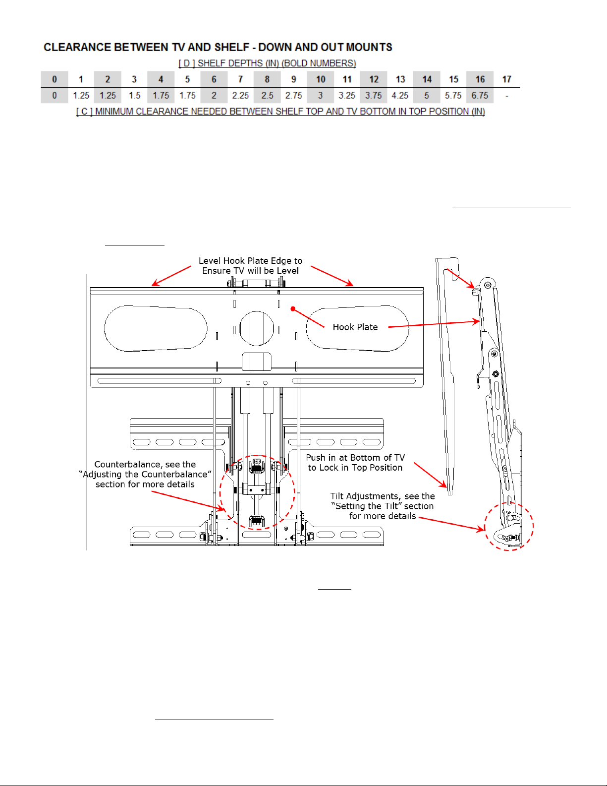
7. Extra thought and planning is needed when mounting over a shelf; see the Above Shelf Mounting section below for more details
and relevant dimensions. Find the needed distances [H] and [C] for your shelf.
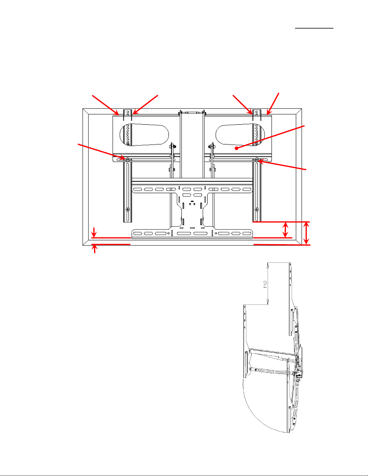
8. To find out how the mount relates to the television you should do a test fitting on the ground and/or you can measure from the
Attach Arms to the television as shown in Figure 4.
9. The Attach Arms are 3 inches higher than the bottom of the mount, so to get the distance between the mount bottom and the
television you can measure the bottom of the Arm to the bottom of the television and subtract 3 inches as seen in Figure 4.
10. Measure out where the bottom of the mount will be, make sure the [H] and [C] minimum distances are satisfied.
11. Use the mount as a template or download and print the Wall Mount Template off of the website and mark the locations of the
mounting holes.
oThe mounting holes need to be in the center of the studs, use a stud finder as needed.

- 5 –
oPut the Level on the top edge of the Hook Plate where the Attach Arms Hook onto, see Figure 4 and 6, this
edge should be level to help ensure a level TV.
o2 mounting holes are needed in the top slots of the mount and 2 in the bottom slots.
o2 mounting holes need to be on each side of the of the center of the mount and the center of gravity of the television
12. Once you know your location pre-drill the 4 mounting holes 2.5in deep using the 1/4in drill bit.
13. Use the 4 3/8in lag bolts with washers to attach the mount to the wall. Tighten with a 9/16in box or socket wrench until the
mount is firmly pressed against the wall. A friend makes this much easier. Do NOT over tighten.
Secure
Arm Here
Secure
Arm Here
Hook Attach Arms
Over Hook Plate Edge
3.0” Arm To
TV
Mount To TV, or
Arm To TV – 3.0”
Hook Plate
Level off of Hook
Plate Edge
Level off of Hook
Plate Edge
Figure 4 Mount Test Fitting
Positions Mount Will Stay At
The Down and Out Mount has a range of positions the mount
will hold the TV at. The general range is shown in Figure 5.
The mount can always stay in the top position.
From the top position down 14 inches the mount can be set to
stay but the angle may not be vertical and the TV will not have a
wide range of positions to stay at. The Mount really isn’t
designed to hold the TV in this range.
From 14 inches to all of the way down the mount can be set to
stay in a wide range of positions. Depending on the weight of
your TV the range will vary. For lighter TVs the mount may stay
in the entire bottom range. For Heavier TVs the mount may only
have a range of about 8 inches.
Figure 5 Positions Mount Will Stay At

- 6 –
Above Shelf Mounting
To get as much downward travel as possible when mounting above a shelf it
is very important that you put extra thought into the mounting process. In
general, the higher the Down and Out Swivel Mount is above the shelf the
more downward travel you will get. Also, the lower the television is
attached on the mount, the higher the Down and Out Swivel Mount can be
mounted to the wall.
Figure 6 and the table below can be used together to calculate how much
downward travel you will get with different shelf depths and heights above
the shelf. The smaller table tells you the minimum height the television
needs to be mounted above the shelf.
For example, you want to find the downward travel [T] when you have a 9
inch shelf depth [D] and you attach the bottom of the mount 7.25 inches
above the shelf [H]. First find the corresponding [D] and look down the
column and find the closest [H], which in this case is 7 and 8.25. Round
down to be on the safe side to 7 inches [H]. Now go left along the row and
find the corresponding Travel [T]. In this case you will get a downward
travel of at least 26.5 inches.
Calculating the clearance needed between the bottom of the television and
the shelf in the up position [C] to ensure the television will not hit the shelf
is much easier. Simply find the shelf depth [D], in this example 9 inches,
and go down the column and find the corresponding height, which is 2.75
inches.
Figure 6 Shelf Clearance Drawing
Shows example with 9in Shelf Depth [D], 26.5in
Downward Travel [T], and Mounted 7in above the
Shelf [H].

- 7 –
Note: All measurements shown on Dynamic Mounting are approximate. The measurements could vary depending on how the mount
is setup, manufacturing tolerances, and the weight of the television.
Attaching the television to the Down And Out Mount
After the above steps are finished you are ready to put the television on the mount.
1. Adjust the counterbalance to the approximate force to handle the weight of your television. See the Adjusting the Counterbalance
section for more details. If in doubt, error to the counterbalance supplying too much force. You can easily adjust force later.
2. Make sure that the Top Tilt Adjustment Bolt is loose and ensure the Top Tilt Cam is free to move, it should come loose out of the
box. See the Setting the Tilt section for more details.
Figure 7 Attaching the Television
3. After the tilt and counterbalance are set, you are ready to put the TV on the mount. You may need a friend to help for heavier
TV’s. Hook the TV Attach Arms over the Hook Plate as shown in Figure 7.
4. As you are hooking the Attach Arms over the Hook Plate, push in on the bottom of the TV to ensure that it locks in the top
position.
5. If the mount doesn’t lock in the top position, the weight of the TV will cause the mount to come down until the counterbalance
takes the load or the mount runs out of travel, while this is happening simply guide the TV down until it stops. Do NOT let go of
the TV until it stops on its own.
6. Before positioning the television side to side, insert the 2 #10 x 7/8 inch long machine screws with washer through the Hook Plate
and into the Attach Arms finger tight to ensure the television will not fall off. Adjust the television to where you want it. Tighten
the screws down with a screwdriver.
7. Adjust the counterbalance so that the television can be moved around as easily as possible but still be able to stay in the desired
bottom position. See the Adjusting the Counterbalance section for more details.

- 8 –
Adjusting the Counterbalance
The counterbalance comes out of the box set for maximum force and will need to be adjusted for the mount to work properly with
your television. To adjust the counterbalance, turn the bottom of the counterbalance screw with only one 9/16 inch box or ratcheting
wrench, see Figure 8. This moves the Counterbalance Block up and down. The approximate counterbalance block settings for various
television weights are shown in Figure 8. In Figure 8 the counterbalance is approximately set for a 65 Pound Television.
Before the Counterbalance block will move, the Spring Washers at the TOP need to be compressed by turning the screw. This means
there will be a few turns where it may seem like nothing is happening. Just keep on turning the bottom of the screw counterclockwise,
it should get harder to turn when you start compressing the gas springs. If the Spring Washers on the BOTTOM are compressing then
you are turning the wrong way.
The Mount comes out of the box set at the Maximum Counterbalance Force. To be able to move the mount without a TV on it, you
need to move the Counterbalance Block to the Minimum Counterbalance Force. At this setting it will still take 15 to 20 pounds of
effort to move the mount which is harder than you think. You should secure it to something to get the mount to move. Once you put a
TV on the mount, everything will work much better.
Figure 8 Counterbalance Settings (Detail from Figure 7)
Counterbalance Noise
Figure 9 Counterbalance Noise
Some noise from the counterbalance is expected. This
is a design that makes moving the TV up and down a
little easier by allowing the counterbalance to float.
To get rid of the noise you can try lubricating the
joints that are rubbing, this may or may not help. The
noise is not causing damage to the mount. To get rid
of the noise for sure, you can turn the half nut that I
highlighted in Figure 9 so that the counterbalance
can’t float as much. Feel free to compress the disc
springs with the nut if needed. By getting rid of the
float the TV will probably be a little heavier to lift up
all of the way. Sorry for the inconvenience.

- 9 –
Moving the Television Up and Down
If the counterbalance is set up correctly the TV should be able to be pushed all of the way up into the top/locked position with
reasonable effort. To unlock from this position simple pull out on the bottom of the television. To get the television all the way to the
bottom position you may need to push down on the television. If the TV pops back up from the desired bottom position, reduce the
counterbalance force. Typically, the force to lift the TV all of the way up is approximately 20-30% of the weight of TV.
Setting the Tilt
In the top position the mount tilts from vertical to about 7 degrees. To set the angle, put the mount in the out position for easier access
and so there isn’t any force on the cam. Adjust the Top Tilt Cam to the desired position and tighten with a 1/2 inch box wrench. There
is a cam on both sides of the mount, use the Top Tilt Alignment Marks to ensure they are at the same position. Move the mount up
and see if the tilt is correct, if not change the position of the cams, it will probably take a few times to get the tilt perfect. If you get a
lot of resistance when trying to push the mount to the Top position, the Cam is set for too much up tilt and you will need to lessen it.
Figure 10 Tilt Adjust (Detail from Figure 7)
To adjust the bottom position tilt you first need to loosen up the 2 Bottom Tilt Lock Nuts with a 7/16 inch box wrench. Next move the
2 Bottom Tilt Adjustment Bolts in and out with the 7/16 inch box wrench until the mount is at the desired tilt, lock down the locknuts
when satisfied with the tilt.
Rubber Bumpers
To help avoid damage to the fireplace shelf, attach the Adhesive Rubber Bumpers to the bottom of the TV mount where it would come
in contact.

- 10 –
Wire Management
Wires can be routed through the wire routing holes and/or zip tied as shown in Figure 11 with the included zip ties. Ensure enough
slack remains so the wires can move freely. Check that nothing is getting pinched or rubbing after running wires.
Figure 11 Wire Routing
Maintenance
To ensure the mount will work great for as long as possible follow these simple procedures;
1. Move the mount up and down at least twice a week, this keeps the seals in the gas springs oiled.
2. Lubricate all joints every 6 months.
3. Visually check all bolts to ensure nothing looks like it is coming loose.
Warranty
Dynamic Mounting guarantees the Down And Out Mount to be free of defects for the product’s warranty period of 3 years.
The warranty period begins on the original date of shipping. The limited warranty is intended only for the original purchaser. The
warranty will be void if the mount is modified in anyway or not installed correctly, Including overloading, abuse, or use for any
purpose other than specified in these directions. This mount is for indoor use only and the warranty will be voided if the mount is
used outdoors.
Dynamic Mounting is not liable for any damage or injury caused from the use of or the inability to use our mount. To the maximum
extent permitted by applicable law, Dynamic Mounting disclaims any responsibility for incidental or consequential damages.
Dynamic Mounting LLC
www.DynamicMounting.com
If you have any questions, please contact info1@dynamicmounting.com
If you would like to speak to someone please email us your phone number and when we can contact you.
Other manuals for Down and Out Mount
2
Table of contents
Other Dynamic Mounting TV Mount manuals