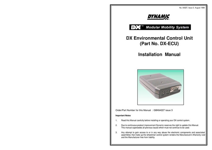
Dynamic DX 12V User manual

No. 60011, Issue 8. October 1998
TM
DX 12V Lighting Module
Installation Manual
Order/Part Number for this Manual : GBK60011 issue 8
Important Notes
1. Read this Manual carefully before installing or operating your DX control system.
2. Due to continuous product improvement Dynamic reserves the right to update this Manual.
This Manual supersedes all previous issues which must not continue to be used.
3. Any attempt to gain access to or in any way abuse the electronic components and
associated assemblies that make up the wheelchair control system renders the
Manufacturer’s Warranty void and the Manufacturer free from liability.

No. 60011, Issue 8. October 1998
Contents
1Introduction ...............................................1
2Related Documentation .....................................2
3General Description ........................................3
3.1 General Features ............................................4
3.2 Safety and Protection Features ................................4
4Specifications .............................................5
4.1 Electrical Specification .......................................5
4.2 Mechanical Specifications ....................................6
4.3 Environmental Specifications ..................................7
5Installation ................................................8
5.1 General ...................................................8
5.2 Mounting ..................................................8
5.2.1 Environmental Protection ...............................8
5.2.2 Securing the 12VLM ...................................9
5.3 12VLM Connection with the DX System ......................11
5.3.1 21 Way Connector Pin Definitions ........................11
5.3.2 Wires and Terminations ..................................11
5.3.3 DXBUS Connections ...................................12
5.3.4 12VLM Connection to the Battery ........................13
5.3.5 Battery Type ...........................................13
5.4 12VLM Connection to the Lighting ..........................14
6Operation ................................................15
6.1 12VLM Activation ........................................15
7Programming ............................................16
7.1 PCD Programmable 12VLM Parameters ......................16
7.1.1 12VLM Parameters .....................................17
7.2 HHP Programmable 12VLM Parameters .....................18

No. 60011, Issue 8. October 1998
8Diagnostics ..............................................20
8.1 DX System Fault Handling .................................20
8.2 12VLM Specific Faults ....................................21
8.2.1 General 12VLM Connection Faults .......................21
8.2.2 12VLM Programming Related Faults ......................21
8.3 Connected Device Faults ...................................22
9Electromagnetic Compatibility (EMC) .........................23
10 Maintenance .............................................24
11 Safety and Misuse Warnings ................................25
11.1 Disclaimer ...............................................26
12 Warranty ................................................27
13 Sales and Service Information ..............................28
14 Appendix A : Abbreviations .................................29
15 Appendix B : 12VLM Accessory Parts List .....................30

No. 60011, Issue 8. October 1998
1 Introduction 1
DX
Remote
DXLighting
Module
DXPower
ModuleDXBUS
DXBUS
24 V
Battery
Left
Indicator
Lights
Side Lights
Right
Indicator
Lights
Motors
1Introduction
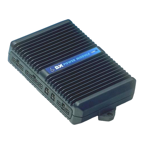
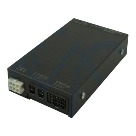
The DX Lighting Module (12VLM) is a TÜV approved DX Module that controls
the lighting system on a power wheelchair. It is used as part of a DX System
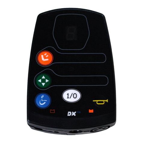
comprising a DX Power Module and a DX Remote with lighting control switches,
as a minimum system. See diagram below.
The lighting consists of side lights and turn indicators. The indicators are flashed
together to provide a hazard warning. The lights are accessed by the DX Remote.
The 12VLM has two standard DXBUS connectors for connection to the DX
System.InaTÜV system,instructions forconnecting theDXBUS andlighting must
be followed.
This manual and others listed below must be read and understood. For more
information contact Dynamic Controls Ltd or an agent as listed in section 13.
Example of minimum DX System with 12VLM

No. 60011, Issue 8. October 1998
2 Related Documentation2
2Related Documentation
A DX based wheelchair control system may comprise between two and sixteen DX
compatiblemodulesdependingontheapplication.EachDXcompatibleModulehas
its own Installation Manual which describes the installation requirements of that
particular Module.
This Manual describes the installation of the 12VLM only and must be read in
conjunction with the:
!DX Power Module (PM) Installation Manual;
!DX Hand Held Programmer (HHP) Manual;
!Dynamic Wizard Installation Sheet / Online Help;
!Installation Manuals for all other DX Modules to be used in your system.

No. 60011, Issue 8. October 1998
3 General Description 3
3General Description
The DX Lighting Module (12VLM) is designed to meet TÜV requirements for
controlling lighting on a power wheelchair. It has two turn indicator outputs and a
side light output, regulated to 13.5V as required by TÜV. Each output can power
multiple lights but must be kept within the electrical specifications limits : see
section 4.1.
The DXBUS is used to control and monitor all DX Modules. The 12VLM connects
to the DXBUS via one DXBUS connector. Power for the 12VLM is drawn from a
separate independent connection to the battery.
The lighting is controlled by buttons on the DX Remote. The turn indicators are
flashed at 75 flashes per minute and both left and right indicator outputs are
activated when the hazard lights are selected. The hazard lights can only be
deactivated by re-selecting the hazard button on the DX Remote. If a DX Combined
LightingActuator Module(CLAM) isinstalled inthe DXSystem, the12VLM takes
over its lighting functions. All lighting outputs are fully protected against short
circuits and voltage transients. The 13.5V regulated supply is protected against
shorts to battery minus, battery plus and overloads.
The12VLM hasdiagnostic capabilitiesdescribed insection 8.If the12VLM cannot
communicate with the DX Remote, the 12VLM automatically generates the hazard
warning.
The electronics are housed in a compact enclosure protected against water, dust and
tampering - see section 4.3 for protection rating.

No. 60011, Issue 8. October 1998
3 General Description4
3.1 General Features
The 12VLM has the following general features:
!Three lighting outputs for driving 12V lamps.
!Fully DXBUS compatible with two identical DXBUS sockets.
!Connection to lights via a standard 21 pin DX connector.
!Powered directly from a 24V wheelchair battery.
!Electromagnetically compatible:
-emitting low levels of RF
-protected against high levels of ESD
!Compact, rugged enclosure providing protection against water and dust up to
IP54.
!Easy slide mounting bracket.
3.2 Safety and Protection Features
The 12VLM has the following safety and protection features:
!Lighting outputs and 13.5V supply protected against external short circuits to
either battery terminal or other outputs.
!Reverse battery protected.
!Detection of a single faulty indicator lamp, and open circuits. Fuse isolation of
short circuit lamps.
!Flashes hazard lights in the event of : wheelchair drive system failure;
communications failure; DXBUS disconnection.

No. 60011, Issue 8. October 1998
4 Specifications 5
4Specifications
4.1 Electrical Specifications
Tamb = -25 to 50EC, VBAT = 24.0 V unless otherwise specified.
Symbol Parameter Conditions Min Nom Max Units
VBAT Battery Voltage 18.0 24.0 32.0 V
PQQuiescent Power All outputs off 1.5 2.0 W
PSB Standby Power 12VLM Off 24 mW
Turn Indicator Output (each output)
ITIO Continuous output Output On 2.3 2.5 A
current
VTIO Output voltage Output On, VTIO= 1.5A, 13.1 13.5 13.9 V
Tamb = 20EC
Side Light (Head/Tail Light) Output
ISLO Continuous output Output On 2.3 2.5 A
current
VSLO Output voltage Output On, VTIO= 1.5A, 13.1 13.5 14.9 V
Tamb = 20EC
13.5V Regulated Power Supply
VREG Output voltage Voltage In 18-32V 12.9 13.6 14.3 V
ITOT Total Lighting Max total lighting 8.0 A
output current load (see note below)
IMAX Max output Supply shorted to ground 7.5 9.0 11.0 A
current
Note : The total lighting output current corresponds to the side lights and hazard
flashing. The supply will current limit at 9A (nominal) to blow fuses. It is not
intended to be used at this level for any extended period of time.

No. 60011, Issue 8. October 1998
4 Specifications6
TM
P/No.
S/No.
MADE IN NEW ZEALAN D BY
WARNING : READ MANUAL
BEFORE
USING THIS PRODUCT.
30
34
6430.5
125
85
M5thread
STATUS MODULE12V IGHTINGL
4.2 Mechanical Specifications
Size: 125 * 85 * 30 mm
Weight: 0.5 kg including the mounting plate.
Mounting: Chassis and tube mounting with optional brackets.
Case material: Pressure die cast aluminium, powder coat finish.
Case Protection: Tamper proof, IP54 if mounted as per mounting
instructions : see section 5.2.

No. 60011, Issue 8. October 1998
4 Specifications 7
4.3 Environmental Specifications
Parameter Min Max Units
Operating ambient temperature range -25 50 EC
Storage temperature range -25 70 EC
Operating and storage humidity 0 90 %RH
RF Immunity < 20 V / m 26 MHZ - 1 GHz, IEC 801-3,
RF Emissions CISPR 11 class B.
ESD ISO 7176 part 21
Durability ISO7176-14. If only one DXBUS outlet
is used on the 12VLM, a DXBUS plug
outlet cover must be inserted on the
unused outlet.
Water and Dust IP54 when mounted as per section 5.2
mounting instructions.
Vibration Specification CTL Test Standard : 4 G’s for 2 hours
per paragraph 4.3.6
Electric Wheelchairs Allows a wheelchair to comply to
ISO7176.
The DX-LM-TUV has been designed to meet the requirements of prEN12184 :
1997 (pending).

No. 60011, Issue 8. October 1998
5 Installation8
5Installation
5.1 General
Installing a 12VLM requires the following steps:
1. Mounting and securing the 12VLM Refer Section 5.2
2. Connecting the 12VLM to the rest of the DX system Refer Section 5.3
3. Connecting the 12VLM to the Lighting Refer Section 5.4
3. Programming the 12VLM Refer Section 7.0
5.2 Mounting
5.2.1 Environmental Protection
The 12VLM must be mounted in a position which offers the maximum protection
from water and mechanical abuse. The 12VLM provides protection up to IP54
when mounted in the recommended orientation as shown below, but other
orientations can be used if environmental conditions are sheltered.

No. 60011, Issue 8. October 1998
5 Installation 9
PlastiteScrews(x2)
M3x10
GSC0170 *
DXAux.Mod.Mounting
Bracket(on LM)
Round Mounting
Tube (18 -24 mm Ø)
DXAux.Mod.Tube
ClampB:GME6052)*
DXAux.Mod.Tube
ClampA:GME60526 *
PlastiteScrews(x2)
Tubes18 -21 mmØ:GSC0175 *
Tubes21 -24 mmØ:GSC0180 *
SquareMounting
Bracket
(18 -24 mm²)
DXAux.Mod.Lock
(GME60525)
(supplied withLM)
5.2.2 Securing the 12VLM
The 12VLM is supplied fitted with a DX Aux Mod Mounting Bracket. This allows
the 12VLM to be chassis mounted, tube mounted, or mounted to another DX
Auxiliary Module as follows:
Round or Square Tube Mounting
Chassis Mounting

No. 60011, Issue 8. October 1998
5 Installation10
M5x12 CSK (x2)
GSC0052 *
DXAux.Mod.Mounting
Bracket(on LM)
DXAux.Mod.
Lock GME60525
(supplied withLM)
AnotherDXAuxiliaryModule
Mounting on other Auxiliary Modules

No. 60011, Issue 8. October 1998
5 Installation 11
Pin
1
2
3
4
5
8
15
16
1
8
3
15
2 4 5
16
Function
DXBUS-
Side Lights-
RightIndicators-
LeftIndicators-
13.6VLighting +
Battery-
DXBUS+
Battery+
5.3 12VLM Connection with the DX System
For TÜV compliance, the 12VLM must be connected as described in the following
sections. Power for the 12VLM is drawn directly from the battery to ensure
independence between the driving and lighting systems on the wheelchair. For
example, a fault in the DX Power Module causing the overload cutout to trip, will
not affect the 12VLMs ability to flash the hazard lights.
5.3.1 21 Way Connector Pin Definition
5.3.2 Wires and Terminations
To build a matching connector to fit to the 21 way connector, the following parts are
available :
DX 21W Plug Housing Part / Order Number GCN 0796
DX 21W Boot Part / Order Number GCN 0795
DX Positronic Contact, FC114N2 (Lge) Part / Order Number GCN 0793
DX Positronic Contact, FC116N2 (Med) Part / Order Number GCN 0797
DX Positronic Contact, FC120N2 (Sml) Part / Order Number GCN 0794
The DX Positronics Contacts are crimp terminals, and are available from Positronic
Industries Ltd or from Dynamic.
Contact GCN 0793 is for crimping to 1.5 - 2.5 mm² (14 - 16 GA) wires.
Contact GCN 0797 is for crimping to 1.0 - 1.5 mm² (16 - 18 GA) wires.
Contact GCN 0794 is for crimping to 0.25 - 0.5 mm² (20 - 24 GA) wires.
All terminations must use at least 1.0 mm² wire.

No. 60011, Issue 8. October 1998
5 Installation12
ToDX
Power
Module
TwoDXBUSConnectors
Not
Connected
5.3.3 DXBUS Connections
Note When only one DXBUS
connector is used on the 12VLM
and the remaining connector is
accessible to the wheelchair user, a
dummy plug should be fitted to the
unused connector. This will comply
with ISO7176.
Like all DX Modules, the 12VLM is connected to the DX system using the
DXBUS. Unlike most other DX Modules, in order to be TÜV compliant, the
12VLM does not have its power supplied via the DXBUS. The 12VLM uses the
DXBUS for communications only and the two power conductors are unused.
The DXBUS cables are available in the following standard lengths:
DXBUS CABLE, Straight, 0.12 M Part/Order Number GSM 630012
DXBUS CABLE, Straight, 0.3 M Part/Order Number GSM 63003
DXBUS CABLE, Straight, 0.5 M Part/Order Number GSM 63005
DXBUS CABLE, Straight, 1.0 M Part/Order Number GSM 63010
DXBUS CABLE, Straight, 1.5 M Part/Order Number GSM 63015
Other cable lengths in multiples of 0.1 m are available on request.
DXBUS cables are also available fitted with a ferrite bead to improve
Electromagnetic Compatibility (EMC).
DXBUS CABLE, Ferrite, 2.0 M Part/Order Number GSM 63020F
Note : The correct positioning of the 12VLM within the DX system is required for
TÜV compliance.

No. 60011, Issue 8. October 1998
5 Installation 13
5.3.4 12VLM Connection to the Battery
The 12VLM has its power
supplied directly from the
battery and not through the
DXBUS. This is a
necessary requirement for
TÜV compliance.
The 12VLM can also be
power from the DXBUS-
and DXBUS+ outputs on
the 21 way connector if
TÜV compliance is not
required.
Note : Heavy lines denote 3 mm² wire. All other wires from the 21 way connector
as specified.
5.3.5 Battery Type
The DX System is designed to perform optimally with either Lead-Acid or Gel Cell
24 V deep cycle batteries, rated at 20 - 120 Amp hours. The maximum average
discharge rate must not exceed half the rated capacity, in Amp hours.
Highcontinuous dischargerates dramaticallyreduces theavailable batterycapacity.
For example, at a discharge rate equal to the rated capacity, the available capacity
it 50 - 60 %. At a discharge rate of half the rated capacity, the available capacity is
70 - 80 %.
Awheelchair that draws maximum average battery current of 20 A, requires a
battery of at least 40 Amp hours. A battery of only 20 Amp-hours, would begin to
suffer a drop in performance at about half of its available capacity. The 40 Amp
hour battery has a full performance range of 4.5 greater than the 20 Amp hour
battery; a 80 Amp hour battery would only increase this range by 2.5 when
compared to a 40 Amp hour battery.

No. 60011, Issue 8. October 1998
5 Installation14
5.4 12VLM Connection to the Lighting
The three lighting outputs are: Pin 2 Side Lights -
Pin 3 Right Indicators -
Pin 4 Left Indicators -
Note : The 12VLM is designed to blow fuses leading to shorted lamps. When
wired as shown, a blown fuse will not prevent other lamps on the same circuit from
continuing to operate.
The Side Light Output is active pull-down when the light is turned on with one
side of the bulb connected to 13.5V. This output is used to power head and tail
lights. Multiple bulbs can be connected to the output in parallel, as shown in the
following diagram.
The Left and Right Indicator Outputs are also active pull-down when the light
is turned on with one side of the bulb connected to 13.5V. Again, multiple bulbs can
be connected on each output.
The 13.5V pin provides the regulated supply used for powering all lighting loads.

No. 60011, Issue 8. October 1998
6 Operation 15
6Operation
6.1 12VLM Activation
The 12VLM is operated by either a DX Remote. Each DX Remote has different
facilities and not all Remotes support a full lighting system. The operation of the
12VLM is therefore very dependent on what remote it is used with, and the
programmable options that are set up for it.
For TÜV compliance, the DX Remote must support the ‘Hazard Lockout’ feature.
That is, while hazard lights are flashing, the turn indicators can not be used. Most
DX Remotes support this feature. Contact a Dynamic Sales and Service Centre for
further information.
Please consult the User Manual for the DX Remote or other DX Module used in
your DX System.

No. 60011, Issue 8. October 1998
7 Programming16
7Programming
7.1 Wizard Programmable 12VLM Parameters
Programmable parameters relating to the 12VLM are contained in the DX Remote
program. This program can be modified using the Wizard, a Programming,
Configuration and Diagnostic tool.
To view and / or edit these parameters:
1. Enter the Wizard’s Main Menu screen as described in the Wizard Installation
Sheet.
2. Use the keyboard or mouse to select the File, Open menu option.
3. Select the ‘SuperChair, Deluxe’ program from the file dialog box.
4. Select the "Edit Module Parameters" menu option.
5. Select ‘Lighting Parameters’.
7. Scroll through the list of parameters and adjust as necessary.
8. Press «Enter» to accept the changes or 'ESC' to exit without saving. Select the
File, Save menu option. These values will now be part of the Chair Program for
the ‘SuperChair, Deluxe’.
Listed on the following page are the relevant LM parameters and their functionality.

No. 60011, Issue 8. October 1998
7 Programming 17
7.1.1 12VLM Parameters
Note : For TÜV compliance, all lighting must be enabled.
12VLM Enable State: yes / no Default: no
Must be set to 'Yes' for 12VLM operation.
This parameter is also programmable using the HHP, see section 7.2.
CLAM Lighting Enable
Must be set to ‘Yes’ for CLAM operation. Should be set to ‘No’ in a LM
system.
Sidelights Enable State: yes / no Default: yes
If set to ‘Yes’, sidelights are enabled.
If set to ‘No’, there will be no response to a DX Remote sidelight (head or tail)
button being pressed (other than a beep from some varieties of DX Remotes).
Lighting buttons can be disabled if the DX Remote used in a system has lighting
buttons that do not have the corresponding lights attached.
Indicators Enable State: yes / no Default: yes
As for the Sidelight Parameter.
Hazard Enable State: yes / no Default: yes
As for the Sidelight Parameter.
Table of contents
Other Dynamic Control Unit manuals
Popular Control Unit manuals by other brands

STIEBEL ELTRON
STIEBEL ELTRON HUV 1 Operating and installation

Flowserve
Flowserve T4E-1 Technical manual

Telit Wireless Solutions
Telit Wireless Solutions BlueMod+S42/AI Hardware user's guide

AB Quality
AB Quality 1769-IQ16F installation instructions

Firgelli
Firgelli FA-SYNC-2 user manual

BHI
BHI NEDSP1962-KBD User & installation manual

iNetVu
iNetVu STM Satlink 2900 user guide

Arsin
Arsin AR1230 user manual

National Instruments
National Instruments Module SCXI-1125 CALIBRATION PROCEDURE

Dormakaba
Dormakaba SCU-DR Mounting instruction

Topcon
Topcon GC-35 Quick reference guide

Feig Electronic
Feig Electronic OBID i-scan D ISC.MU02.02 Installation