manuals.online logo
Brands
  1. Home
  2. •
  3. Brands
  4. •
  5. Dormakaba
  6. •
  7. Control Unit
  8. •
  9. Dormakaba SCU-DR User guide

Dormakaba SCU-DR User guide

WN 059726 45532 – 2018-11
EN
SCU-DR
Mounting instructions
1 About this document
1.1 Content and purpose
This document describes the mounting of the SCU-DR
and the connection to a SafeRoute® system.
1.2 Target group
This document is intended for assembling technicians
and specialists authorized to carry out installation by
dormakaba.
1.3 Other applicable documents
The following documents belong to the unit’s
complete documentation and must be observed:
• The SafeRoute® system manual
• The respective door unit’s inspection log
• The approved components’ declaration of
conformity
1.4 Documents storage
This document must be handed over to the facility
operator after mounting and commissioning.
1.5 Symbols used
1. 2. Sequence of action steps
6Reference to a chapter
Components may be damaged by
electrostatic discharge. Ground
your own body before touching a
component!
2 Safety
2.1 Intended use
The SCU-DR controls the SafeRoute® electrical
locking system from dormakaba.
2.2 Personnel qualification
Mounting may only be carried out by persons
authorized by dormakaba.
3 Product description
The SCU-DR is a DCW® component for controlling
escape route doors. The SCU-DR must be installed on
a 35 mm DIN rail in a housing. The housing must at
least meet the requirements of IP 30.
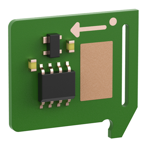
The inserted license card turns the SCU-DR into a
SafeRoute® Control Unit in a SafeRoute® escape route
security system.
3.1 Parts included
• SafeRoute® Control Unit SCU-DR
3.2 Technical information
Supply voltage: 24VDC +/- 15 %
Power consumption: 30mA
Ambient temperature: -10 °C to +55 °C
Protection class: Dependent on housing
Inputs
In 1 to In 4
Current consumption of
inputs per input:
at 5V AC/DC: 3mA
at 12V AC/DC: 8mA
at 24V AC/DC: 17mA
at 28V AC/DC: 28mA
Outputs
Out1 to Out2
For each active relay,
the current consumption
increases by approx.
12mA
Contact load capacity: 24V, 1A
Contents
1 About this document 1
2 Safety 1
3 Product description 1
4 Mounting 2
5 Disassembly, recycling and disposal 4
2SCU-DR 2018-11
WN 059726 45532
dormakaba Mounting instructions Mounting
4 Mounting
4.1 Mounting the SCU-DR
4.2
J-Y(St)Y
2x2x0.8
1.
2.
CR 1220
++
1
2
3
SLI license card
(optional)
Battery
(optional)
1.
2.
1.
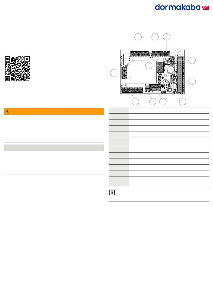
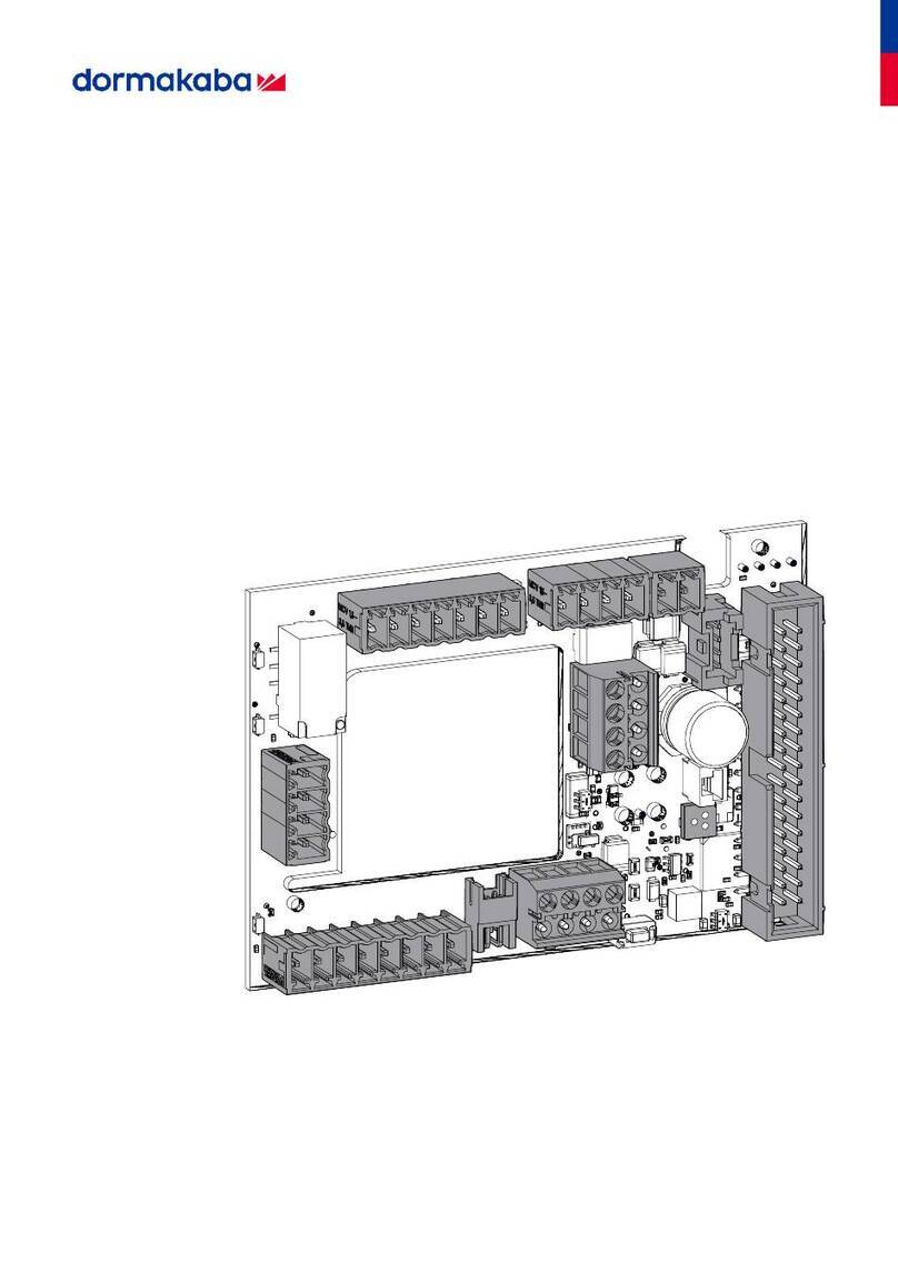
4.2 Assignment of terminals and switch/button
S601
S600
In 1In 2 In 3 In 4 GND 24V1AB3
Out 1 Out 2 Out 3 Out 4 GND 24V
DCW
BAT
USB
SLI
Service
GND
Mode1
AS
Sabo
Rx
Tx
Mode2
GND
1G
1 AS
Sabo
GND
Tx
Rx
GND
X500 X504X502X402
X506 X510X507X400
NO
C
NC
NO
C
NC
NO
C
NC
NO
C
NC
GND 24V
GND 24V
In 1In 2 In 3 In 41AB3
3SCU-DR 2018-11WN 059726 45532
dormakaba Mounting instructions Mounting
X400 +24VDC
GND
DCW® bus
X402 GND
Tx
Rx
GND
RS232 interface
Tamper contact (external cover/housing contact, opener)
Alarm system, e.g. BMA, smoke detector, etc.
+24VDC
switched voltage (test "SVP-PR DCW® / M-SVP-PR DCW®")
X502 GND
GND
+24VDC
+24VDC
X507 GND
GND
+24VDC
+24VDC
X500
Out1
Out2
Default:
Common alarm
Default:
Common alarm
Contact load capacity:
24V, 1A
Contact load capacity:
24V, 1A Parameterizable via TMS Soft®.
For multi-door systems
Out 1 to Out 4 are assigned to the
corresponding door numbers 1 to 4.
X504
Out3
Out4
Default:
Common alarm
Default:
Common alarm
Contact load capacity:
24V, 1A
Contact load capacity:
24V, 1A
X506 In1
In2
Optocoupler
5-28VAC/DC
Optocoupler
5-28VAC/DC
Default: Static control
Parameterizable via TMS Soft®.
For multi-door systems In1 to In4
are assigned to the corresponding
door numbers 1 to 4.
X510 In3
In4
Optocoupler
5-28VAC/DC
Optocoupler
5-28VAC/DC
Default: Static control
Tamper
ON
1234
1234
ON
1234
ON
Service switch for tamper alarm suppression for all connected doors
ON = Service (tamper alarm turned off)
OFF = Operation (tamper alarm activated)
AS
ON
1234
1234
ON
1234
ON
Alarm system switch
ON = alarm system activated
OFF = alarm system not connected (default)
Mode1
Mode2
ON
1234
1234
ON
1234
ON
DIP switches Number of doors DIP switch 3 DIP switch 4
1
2
3
4
0
1
0
1
0
0
1
1
Service Service button
dormakaba Deutschland GmbH
DORMA Platz 1 58256 Ennepetal Germany T: +49 2333 793-0 F: +49 2333 793-4950 www.dormakaba.com
Translation of the original document, subject to change without notice
4.3 LED displays
BTRDCW
SLI
LED on LED off
LED flashes slowly LED flashes quickly
SLI
License card inserted
License card not inserted
License card defective
DCW®
Bus connection OK
Bus connection interrupted
(Safe DCW® node)
Bus connection interrupted
(not Safe DCW® node)
BTR (functions only with inserted license card)
No node configured
Configuration mode active
Operation
License error
4.4 Complete mounting
1. Document the mounting and commissioning in the
inspection log.
2. Hand over this document to the facility operator.
5 Disassembly, recycling and
disposal
Disassembly is carried out in the reverse order of
mounting and must be carried out by qualified
personnel.
The product must be disposed of in an
environmentally friendly manner. Electro-
technical parts and batteries must not be
disposed of as domestic waste. Dispose of
electrotechnical parts and batteries in the designated
acceptance and collection points. Refer to the
statutory regulations for your country.

Other Dormakaba Control Unit manuals

Dormakaba LA GARD 700 Series User manual

Dormakaba

Dormakaba LA GARD 700 Series User manual

Dormakaba UNIQUIN User manual

Dormakaba

Dormakaba UNIQUIN User manual

Dormakaba SIO-DR User manual

Dormakaba

Dormakaba SIO-DR User manual

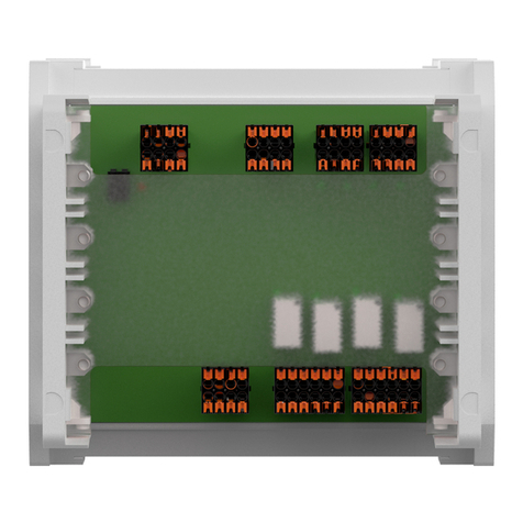
Dormakaba ED connection board CAN User manual

Dormakaba

Dormakaba ED connection board CAN User manual

Dormakaba SLI-A Interlock User manual

Dormakaba

Dormakaba SLI-A Interlock User manual

Dormakaba MFC User manual

Dormakaba

Dormakaba MFC User manual

Dormakaba SafeRoute SCU-UP User manual

Dormakaba

Dormakaba SafeRoute SCU-UP User manual

Dormakaba MotionIQ ED-CAN User manual

Dormakaba

Dormakaba MotionIQ ED-CAN User manual

Popular Control Unit manuals by other brands

HYDAC FILTER SYSTEMS FCU 2000-4 Series Operating and maintenance instructions

HYDAC FILTER SYSTEMS

HYDAC FILTER SYSTEMS FCU 2000-4 Series Operating and maintenance instructions

Quectel EC25 series Hardware design

Quectel

Quectel EC25 series Hardware design

Siemens SIMOVERT Masterdrives SSB operating instructions

Siemens

Siemens SIMOVERT Masterdrives SSB operating instructions

Spencer Self Switch user manual

Spencer

Spencer Self Switch user manual

Autocall 4010ES manual

Autocall

Autocall 4010ES manual

MG R30US4 instruction manual

MG

MG R30US4 instruction manual

Burkert 8695 quick start

Burkert

Burkert 8695 quick start

ASTEL MGR100 operating instructions

ASTEL

ASTEL MGR100 operating instructions

M-system R3-NE1 instruction manual

M-system

M-system R3-NE1 instruction manual

Danfuss ASV-PV instructions

Danfuss

Danfuss ASV-PV instructions

Pioneer CX-3168 Service manual

Pioneer

Pioneer CX-3168 Service manual

Allen-Bradley POINT I/O 1734-232ASC user manual

Allen-Bradley

Allen-Bradley POINT I/O 1734-232ASC user manual

Greentek VECTRA SERIES Installation and owner's guide

Greentek

Greentek VECTRA SERIES Installation and owner's guide

KROHNE OPTISWITCH 3100 C Handbook

KROHNE

KROHNE OPTISWITCH 3100 C Handbook

Booma-RC Intellimatch IM22 quick start guide

Booma-RC

Booma-RC Intellimatch IM22 quick start guide

KERAFLO AYLESBURY KB Series quick start guide

KERAFLO

KERAFLO AYLESBURY KB Series quick start guide

AVANCIS POWERMAX 100 Safety, installation, and operation manual

AVANCIS

AVANCIS POWERMAX 100 Safety, installation, and operation manual

Emerson Fisher POSI-SEAL A81 instruction manual

Emerson

Emerson Fisher POSI-SEAL A81 instruction manual

manuals.online logo
manuals.online logoBrands
  • About & Mission
  • Contact us
  • Privacy Policy
  • Terms and Conditions

Copyright 2025 Manuals.Online. All Rights Reserved.