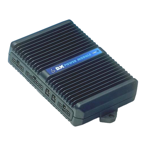
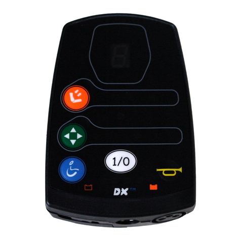
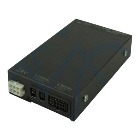
Dynamic DX2-GYRO Installation and operating instructions

DX2-PMA90LG
INSTALLATION MANUAL ADDENDUM
THE
ULTIMATE
POWERCHAIR
CONTROL
SOLUTION
DX2-GYRO
DX2-PMA90LG
GYRO


About this Manual Addendum
This manual can help you understand and install the DYNAMIC DX2-PMA90LG Power Module.
It describes the general principles, but it gives no guidelines for specific applications. If there is a
specific requirement for your application, please contact Dynamic Controls or one of the sales
and service agents to assist you.
The product is part of the DX System. This manual must be read together with the DX System
Manual and all other relevant DX and DX2 component manuals.
In this manual, a few symbols will help you identify the purpose of the paragraph that follows:
Notes & Precautions:
Notes provide supporting information in order to install, configure, and use
the product. Not following the instructions given in notes or precautions can
lead to equipment failure.
Warnings:
Warnings provide important information that must be followed in order to
install, configure, and use the product safely and efficiently. Not following the
instructions given in a warning can potentially lead to equipment failure,
damage to surrounding property, injury or death.
The term ‘programming’ used in this manual refers to adjusting parameters and configuring
options to suit an application. ‘Programming’ does not change or alter any software within the
controller and is performed using a controlled programming tool available only to authorised
personnel.
The term ‘accessory’ used in this manual refers to equipment that is ancillary to the main
functioning of the DX System. It does not refer to an accessory of the powerchair.
The DX System is a component of the powerchair.
The DX System is not user serviceable. Specialised tools are necessary for the repair of any
component.
Do not install, maintain or operate this equipment without reading, understanding and
following this manual –including the Safety and Misuse Warnings –otherwise injury or damage
may result. This manual contains integration, set-up, operating environment, test and
maintenance information needed in order to ensure reliable and safe use of the product.
Due to continuous product improvement, DYNAMIC reserves the right to update this manual.
This manual supersedes all previous issues, which must no longer be used.
DYNAMIC reserves the right to change the product without notification.
Any attempt to gain access to or in any way abuse the electronic components and
associated assemblies that make up the powerchair system renders the manufacturer’s
warranty void and the manufacturer free from liability.
DYNAMIC, the DYNAMIC logo, the DX logo and the DX2 logo are trademarks of Dynamic Controls.
All other brand and product names, fonts, and company names and logos are trademarks or
registered trademarks of their respective companies.
DYNAMIC owns and will retain all trademark rights and DYNAMIC or its licensors own and will retain
all copyright, trade secret and other proprietary rights, in and to the documentation.
All materials contained within this manual, in hardcopy or electronic format, are protected by
copyright laws and other intellectual property laws.
© Copyright 2012 Dynamic Controls. All rights reserved.

GBK65248: Issue 2.03 - May 2012
4
Contents
1Introduction to the DX2-PMA90LG ........................ 5
2Specifications.......................................................... 6
2.1 Electrical Specifications ............................................................ 6
2.2 Mechanical Specifications....................................................... 7
2.3 The DX2-GYRO Module ............................................................. 8
3Installation ............................................................... 9
3.1 Connect to the DX System ....................................................... 9
3.2 Connect to the DX2-GYRO module........................................ 9
3.3 Setup procedure for the Gyro................................................ 10
3.3.1 Preparation .................................................................... 10
3.3.2 Gyro set-up procedure ................................................ 10
3.4 Gyro Tuning Plug-in .................................................................. 12
4Programming......................................................... 13
4.1 Parameter List ........................................................................... 13
4.2 Parameter descriptions ........................................................... 14
4.2.1 Gyro Configuration....................................................... 14
4.2.1.1 Gyro Profile Select .............................................................14
4.2.2 Gyro Profiles ................................................................... 15
4.2.2.1 Gyro Profile Name .............................................................15
4.2.2.2 Gyro Kp Gain (Proportional Gain)..................................15
4.2.2.3 Gyro Ki Gain (Integral Gain)............................................16
4.2.2.4 Gyro Kfr Gain (Filtered Response Gain) ........................16
4.2.2.5 Gyro Angular Speed Scalar.............................................17
4.2.2.6 Gyro Fault Speed Limit......................................................17
5Troubleshooting..................................................... 18
5.1 OONAPU conditions ................................................................ 18
5.2 Gyro Faults................................................................................. 18
6Appendices........................................................... 19
6.1 Intended Use and Regulatory Statement ............................ 19
6.2 Safety and Misuse Warnings................................................... 19

GBK65148: Issue 2.03 - May 2012
5
1Introduction to the DX2-PMA90LG
The DX2-PMA90LGis a DX2-PMA Power Module variant that can connect to a
DX2-GYRO Module.
The Gyro module can help to keep the chair straight on challenging terrain by
measuring the physical movement of the chair. If the chair does not go in the
intended direction, the Gyro power module makes small corrections until the chair
does go in the intended direction.
Warning:
Gyro Control cannot be used inside moving vehicles such as buses or trains. If
a chair with Gyro Control is used on a bus or a train, make sure that either the
DX System is powered off or that a non-Gyro stabilised Drive Profile is selected
before the vehicle starts moving.
The Gyro module is not operational as long as the joystick is in the neutral
position.
Note:
The Gyro control is designed to operate correctly during tyre slip. However, if
extreme tyre slip occurs, the Gyro may not be able to correct the direction of
the chair anymore. In this case, a Gyro fault may occur and the chair may
come to a sudden stop. To reset the Gyro fault, turn the power off and on.
Note:
The DX2-PMA90LG is a variant of the DX2-PMA Power Module family.
This document is an addendum to the DX2-PMA power Module installation
manual. Read the DX2-PMA Power Module installation manual before
reading this addendum.
All warnings and configurations presented in the DX2-PMA installation
manual are also applicable to the DX2-PMA90LG, except where specifically
stated differently in this addendum.
GYRO

GBK65248: Issue 2.03 - May 2012
6
2Specifications
2.1 Electrical Specifications
Parameter
Min
Nom
Max
Units
Battery Voltage
18
24
32
V
Battery Saver
High threshold
Low threshold
21
18
Quiescent Power (relay de-energised)
2
5
W
Standby Power
15
20
mW
Thermal limit
70
˚C
DX BUS
CANH and CANL tolerated Voltage
0
38
V
DX BUS supply current @ 40˚C
12
14.9
A
Motor Outputs
Motor Type
24V
DC
Maximum output voltage
23.5
V
Continuous motor current (@ 20˚C ambient temperature)
30
A
Peak motor current
*15 min @ 20˚C initial case temperature
**30 sec @ 20˚C initial case temperature
***0.1 - 1.5 sec (programmable boost time)
35*
90**
120***
A
PWM frequency
16
19.6
20
kHz
Stall timer (programmable)
2
15
60
s
Park brake outputs
Output voltage
Vbat -
1.1
Vbat
V
Output current
0.6
1
A
Configuration: single/dual
Lighting outputs
Supply Voltage
18
24
32
V
Output power (per output)
50
W
Output current (per output)
2
A
On Board Charger supply
Voltage
24
V
Current
15
A
Inhibit
via DCI input (see 3.2.6.3 of
DX2-PMA installation manual)
Warning:
Make sure that the total power consumption of all modules in
the DX System does not exceed the rated DX BUS current at any time.

GBK65148: Issue 2.03 - May 2012
7
2.2 Mechanical Specifications
All dimensions ± 0.5 mm.
Parameter
Min
Nom
Max
Units
Installed depth including connectors
140
5.51
mm
inch
Mounting torque (M5 bolts)
2
4.5
Nm
Weight
1040
g
Operating Temperature Range
-25
(-13)
50
(122)
°C
(°F)
Storage Temperature Range
-40
(-40)
65
(149)
°C
(°F)
Operating Humidity Range
0
90
%RH
Battery Connector Cycles
10
cycles
Motor Connector Cycles
100
cycles
Material
pressure die cast aluminium alloy
Protection rating
IPx4
Warning:
To achieve the specified IPx4 rating, do not mount the DX2 Power Module
with the connectors facing upward. In addition, add a water shielding cover
if necessary to protect the Power Module from water entry as appropriate to
the environment that the chair will be used in.
M5

GBK65248: Issue 2.03 - May 2012
8
2.3 The DX2-GYRO Module
Ensure that the DX2-Gyro module is mounted in a true vertical axis
(exactly 90 degrees to the horizontal ground level). Two mounting
holes are required: one for the M6 mounting bolt, the second for the
orientation spigot.
The orientation spigot, located towards the top of the module (see
diagrams below), ensures that the Gyro module cannot rotate out of
position once it has been secured to the wheelchair frame.
Front view
Rear view
Side view
Top view
The cable length is 600 mm. For connector information see section 3.2.
Note:
Mount the DX2-GYRO module so that the cable is located on the top side of
the unit, with the cable rising vertically upwards. The module will not function
in any other position.
Warning:
Mount the Gyro module in a position where the user cannot touch it.
Orientation
spigot
Orientation
spigot

GBK65148: Issue 2.03 - May 2012
9
GYRO
3Installation
3.1 Connect to the DX System
In contrast to all other DX2-PMA variants, the DX2-PMA90LG module only has one
DX BUS socket. The socket that the other variants use as a second DX BUS connection
is used for the DX2-GYRO module.
To connect multiple DX Modules to the Power Module, either use a DX BUS Y-cable
(GCB65231) or a straight cable to a 4-way DX BUS socket (DX-SKT-X4).
Precautions:
Connect high current modules such as an Actuator Module as close as
possible to the Power Module (see DSM section 3.2).
3.2 Connect to the DX2-GYRO module
The leftmost socket on the DX2-PMA90LG connects to the DX2-GYRO module.
To avoid confusion with the DX BUS socket, the GYRO socket is clearly marked with a
white rectangle. The DX2-GYRO module has a cable with a white connector that can
help to recognise the correct connection: the white connector goes into the socket
with the white rectangle.
Precaution:
The DX2-GYRO connector is physically identical to the DX BUS connector.
If both cables are swapped, no damage will occur to either the Gyro
module or the power module. However, the DX System will not start up if the
connectors are swapped. It is therefore important to make sure that the
connectors are inserted in the correct socket.
DX BUS

GBK65248: Issue 2.03 - May 2012
10
3.3 Setup procedure for the Gyro
3.3.1 Preparation
The Gyro module gives the most comfortable results on a chair that has already been
set up to provide optimal performance and steering stability without the Gyro control.
If the chair has not been set up for steering stability, the Gyro will still correct the
direction of the chair and keep the chair straight, but it has to make bigger
corrections which results in jerky and uncomfortable driving. Please set up the
following parameters first, before activating the Gyro control.
Load Compensation
Speed @ Maximum
Acceleration
Deceleration
See the DX System Manual on how to set up these parameters with Wizard.
Note:
Ensure your Wizard is updated to the latest available version (version 5.6.6 or
later), which contains the Gyro Tuning Plug-in, and three new system builder
templates for Gyro. You can create a new Gyro programme using the
templates, or you can convert an existing DX2-PMA90L programme into a
DX2-PMALG version. Under "Tools", click on "Change Module Version" and
select the Power Module and change this to the DX2-PMA90LG Version.
Repeat this for "Change Module Type". You need to change both Version
and Type for the conversion to work properly.
Parameters that can help to keep the chair straight on Front Wheel Drive chairs:
Non-Linear Turn decreases the sensitivity of the joystick for small sideways joystick
deflections. This makes it easier to keep the chair straight when unintended small
joystick movements occur.
A reduced Turning @ Full Speed decreases the sideways sensitivity of the joystick
when the joystick is fully deflected forward. This makes it easier to keep the chair
straight at full speed.
After setting up the above parameters, check that the chair is already reasonably
driveable without the Gyro control. If this is the case, proceed to set up the Gyro.
3.3.2 Gyro set-up procedure
The DX2 Gyro works by combining input demand from a joystick or switch source with
digital gyroscopic information about the direction that the wheelchair is tracking.
When the system detects that the wheelchair is deviating from the intended course of
direction it automatically corrects the path of travel. The system has four key
parameters that must be specifically tuned to each wheelchair design configuration:
The Angular Speed Scalar calibrates the Gyro to a particular wheelchair
configuration. This is the most critical value and must be set up before any
other Gyro values are adjusted. A calibration tool is included for this in the
latest Wizard PC tool.

GBK65148: Issue 2.03 - May 2012
11
Proportional (Kp) gain affects the rate at which the Gyro will respond to fast
changes in wheelchair direction to provide angular velocity stability.
Integral (Ki) gain processes Gyro information over a longer period of time and
this value influences the straight tracking of a wheelchair to provide
directional stability.
Filtered Response (Kfr) gain is an optional setting that dampens the sensitivity
of joystick signals relative to the Gyro response. Tuning this parameter can
provide benefits for users with tremor or inaccurate movements, as well as
enabling the integral Ki gain to be set to a higher value to provide better
straight line drive performance.
The procedure is as follows:
1. Assign a Gyro Profile to a Drive profile using Gyro Profile Select.
2. Check that:
oGyro Kp Gain is set to zero,
oGyro Ki Gain is set to zero,
oGyro Kfr Gain is set to 255.
3. Drive the chair to a flat surface where the chair can turn freely without wheel slip.
4. Set Gyro Angular Speed Scalar to the correct value using the
Gyro Tuning Plug-in (see section 3.4 next).
5. Select the drive profile that has the Gyro module enabled.
6. Slowly drive down a ramp and stop. Increase the value of Gyro Kp Gain until the
chair starts to vibrate during stopping on the ramp. The vibration means that the
parameter is set too high. Decrease the value until the vibrating stops.
7. Drive in a straight line at full speed. Increase Gyro Ki Gain until the chair starts to
make slow jerks or starts to swerve. This makes the chair feel uncomfortable and
shaky even though the direction is kept constant. Decrease Gyro Ki Gain until the
chair feels comfortable again. Usually Gyro Ki Gain has a much lower value than
Gyro Kp Gain. There are exceptions, therefore always test to make sure that the
chair drives comfortably.
8. If the chair reacts too responsively to unintended small joystick movements,
decrease Gyro Kfr Gain. Please note that decreasing this parameter can
introduce steering delays.
9. Set Gyro Fault Speed Limit to a value that keeps the chair safe when the Gyro
module loses connection or is faulty.
Warning:
The Gyro cannot be used on moving vehicles, such as buses or trains.
For this reason, there should always be at least one drive profile that does not
have the Gyro control enabled.
To achieve this, do not activate the Gyro on Drive Profile 1. Program this
profile so that the chair is always safe and stable to drive without Gyro
assistance, for example by limiting the maximum speed.

GBK65248: Issue 2.03 - May 2012
12
3.4 Gyro Tuning Plug-in
The Wizard 'Gyro Tuning Plug-in' provides a convenient tool for OEMs to determine the
best value for the Gyro Angular Speed Scalar parameter (4.2.2.5).
The Gyro Angular Speed Scalar parameter determines the way that the signals
coming from the Gyro module are interpreted, and as such affects all other Gyro
operational parameters.
Set up this parameter first, before tuning any of the other Gyro parameters.
Note:
1) Before you start the plug-in, drive the chair to a place where it can turn
freely. Once the plug-in is started, the chair will not drive forward or reverse,
it will only drive in circles.
2) The plug-in may require the COM port for Wizard to be set to a COM port
number of 9 or less. To change the COM port in Wizard, go to Tools
Options and then change the COM port number with the
Communications Port drop-down box.
To start the plug-in, click on Tools Plug-ins Gyro Tuning Tool
Click Start. [Note: You may need to increase the Max Turning Speed of the chair
to get it to spin fast enough for a good calibration reading.]
Follow the instructions: spin in one direction until you see "Tuning Successfully
Completed".
Click Start again.
Spin in the other direction until you see "Tuning Successfully Completed".
Use the average of the two values as the value for Gyro Angular Speed Scalar.
Warning:
It is critical that the wheels do not slip at all during the use of the plug-in.
If the wheels slip during the turning procedure, the measured value for Gyro
Angular Speed Scalar will be wrong. If this value is used, the Gyro module will
not operate correctly, which can make the wheelchair unsafe.

GBK65148: Issue 2.03 - May 2012
13
4Programming
Warning:
Read the programming chapter of the DX2-PMA installation manual, and the
DX System Manual programming chapter (DSM chapter 7) including all its
warnings and notes before reading this chapter.
The programming chapter of this manual only describes Gyro specific
programming.
4.1 Parameter List
This manual addendum only describes the Gyro parameters.
For all other parameters, see the DX2-PMA installation manual.
Key: Editable at this level (see section 7.1.2.1 of the DX System manual)
Viewable at this level
Parameter
Possible Values
Default
HHP
Lite
Std
Adv
Gyro Configuration (4.2.1)
Gyro Profile Select
Gyro Off
Profile G1
Profile G2
Profile G3
Profile G4
Gyro Off
-
Gyro Profiles (4.2.2)
Gyro Profile Name
any name
-
Gyro Kp Gain
0 - 255
0
-
Gyro Ki Gain
0 - 255
0
-
Gyro Kfr Gain
0 - 255
255
-
Gyro Angular Speed Scalar
10 - 255
35
-
Gyro Fault Speed Limit
0 - 100 %
10 %
-

GBK65248: Issue 2.03 - May 2012
14
4.2 Parameter descriptions
4.2.1 Gyro Configuration
4.2.1.1 Gyro Profile Select
Parameter
Possible Values
Default
HHP
Lite
Std
Adv
Gyro Profile Select
Gyro Off
Profile G1
Profile G2
Profile G3
Profile G4
Gyro Off
-
This parameter is only used in the DX2-PMA90LG Power Module in combination with a
DX2-GYRO stabilisation module. Gyro stabilisation will only occur when a DX2-GYRO
module is connected to the Power Module.
The Power Module has 4 Gyro Profiles (G1 - G4) that can be used to adapt the Gyro
behaviour to different circumstances, for example smooth or rough terrain.
The Gyro Profile Select parameter assigns a specific Gyro Profile to a Drive Profile, to
provide Gyro stabilised drive performance in that Drive Profile. Each Drive Profile can
have its own Gyro Profile.
To disable Gyro use in a Drive Profile (for example, a Drive Profile for use on buses or
trains), set Gyro Profile Select for that Drive Profile to 'Gyro Off'. In this case the
standard drive parameters are used and no Gyro stabilisation occurs.
Notes:
1. It is not possible to switch between a non-Gyro Drive Profile and a Gyro
Drive Profile while driving. If a switch is made during driving, the chair will
stop and an OONAPU condition will occur. The joystick must be released
to the centre before the chair will drive again.
2. If the Gyro module is not connected and a Gyro-stabilised Drive Profile is
selected, the Gyro Profile limits the maximum speed of the chair to the
value of the Gyro Fault Speed Limit parameter (4.2.2.6). This makes sure
that the chair remains stable in the absence of Gyro stabilisation.
Warning:
Gyro Control cannot be used inside moving vehicles such as buses or trains.
If a chair with Gyro Control is used on a bus or a train, make sure that either
the DX System is turned off or that a non-Gyro stabilised drive profile is
selected, before the vehicle starts moving. To achieve this, the user must be
able to select a Drive Profile where the Gyro Profile is set to ‘Gyro Off’.
The Gyro module is not operational as long as the joystick is in the neutral
position.

GBK65148: Issue 2.03 - May 2012
15
4.2.2 Gyro Profiles
The Power Module has 4 Gyro Profiles that can be used to adapt the Gyro behaviour
to different circumstances, for example smooth or rough terrain.
Each of the parameters below can be set for each Gyro Profile separately.
4.2.2.1 Gyro Profile Name
Parameter
Possible Values
Default
HHP
Lite
Std
Adv
Gyro Profile Name
any name
-
Gyro Profile Name offers installers/OEMs the possibility to give a name to a Gyro
Profile. For example, a name that identifies specific chair models or drive and usage
situations.
The name field is 8 characters long.
4.2.2.2 Gyro Kp Gain (Proportional Gain)
Parameter
Possible Values
Default
HHP
Lite
Std
Adv
Gyro Kp Gain
0 - 255
0
-
Gyro Kp Gain determines how much the Gyro reacts to fast changes in direction.
When this parameter is set correctly, the wheelchair will feel responsive, and turn
largely as directed by the joystick with minimal tyre slip.
When this parameter is set too low, the Gyro effect will be less and it will be difficult to
maintain a straight line course at any significant speed, additionally a user may
experience gross tyre slip and rapid rotational acceleration when attempting to exit a
turn.
When this parameter is set too high, the chair feels harsh and vibrates, especially
when accelerating/decelerating or descending a hill.
Warning:
Excessively large values of Gyro Kp Gain can be dangerous. Values of Kp in
excess of that required to meet a specified performance objective should be
avoided.

GBK65248: Issue 2.03 - May 2012
16
4.2.2.3 Gyro Ki Gain (Integral Gain)
Parameter
Possible Values
Default
HHP
Lite
Std
Adv
Gyro Ki Gain
0 - 255
0
-
Gyro Ki Gain determines how much the Gyro reacts to slow changes in direction.
When this parameter is set correctly, the wheelchair will drive in a straight line over
significant distances and it will not veer when it drives on sloping terrain.
When this parameter is set too low, the Gyro effect will be less and the benefits
described above are reduced.
When this parameter is set too high, the chair may start to swerve slightly from left to
right when driving in a straight line, and when turning, the chair may keep on turning
a bit more after the user already has stopped turning.
Warning:
Excessively large values of Gyro Ki Gain can be dangerous. Values of Ki in
excess of that required to meet a specified performance objective should be
avoided.
4.2.2.4 Gyro Kfr Gain (Filtered Response Gain)
Parameter
Possible Values
Default
HHP
Lite
Std
Adv
Gyro Kfr Gain
0 - 255
255
-
The Power Module compares the actual movement of the chair with the joystick
input (the intended direction). If the user has a tremor, the joystick input does not
always accurately represent the intended direction of the chair.
To compensate for this, the joystick input is filtered before it is compared with the
actual movement of the chair. Gyro Kfr Gain determines how much the joystick input
is filtered.
0 - Maximum filtering is applied
255 - The joystick input is not filtered at all
For normal use, no filtering is needed - set this parameter between 200 -255.
Set this parameter to lower values if the Gyro module overcompensates due to
sudden unintended joystick movements.
If this parameter is set too low, the chair response may feel delayed.

GBK65148: Issue 2.03 - May 2012
17
4.2.2.5 Gyro Angular Speed Scalar
Parameter
Possible Values
Default
HHP
Lite
Std
Adv
Gyro Angular Speed Scalar
10 - 255
35
-
Gyro Angular Speed Scalar calibrates the Gyro Control for the width of the
wheelchair, and the type of motors and gearbox.
When this parameter is set correctly, the wheelchair will turn at the same speed with
and without Gyro control enabled.
Note:
Gyro Angular Speed Scalar affects the operation of Gyro Kp Gain
(Proportional Gain) and Gyro Ki Gain (Integral Gain). For this reason, set Gyro
Angular Speed Scalar to the correct value before tuning any of these
parameters.
The Wizard has a plug-in that can determine the appropriate value for this parameter
automatically. See Gyro Tuning Plug-in (3.4) for details.
4.2.2.6 Gyro Fault Speed Limit
Parameter
Possible Values
Default
HHP
Lite
Std
Adv
Gyro Fault Speed Limit
0 - 100 %
10 %
-
If a Drive Profile is selected that is configured for Gyro operation, and the DX2-GYRO
module is not connected or gives faulty signals, the maximum speed of the chair is
limited to Gyro Fault Speed Limit.
The speed limit makes sure that the chair remains stable in the absence of Gyro
stabilisation.
Warning:
Do not set this parameter too high, otherwise the stability of the chair may be
compromised during a Gyro fault.
Battery voltage

GBK65248: Issue 2.03 - May 2012
18
5Troubleshooting
5.1 OONAPU conditions
While driving, it is not possible to
switch between a non-Gyro Drive Profile and a Gyro Drive Profile, or
switch between Drive Profiles that have Different Gyro Profiles selected in their
Gyro Profile Select field (4.2.1.1), for example G1 and G2.
If a switch is made during driving, the chair will stop and an OONAPU condition will
occur. The joystick must be released to the centre before the chair will drive again.
Out Of Neutral At Power Up is a feature that prevents sudden and unexpected
powerchair movements if the joystick is out of the centre when the controller is turned
on or an inhibit condition is removed. For information on how an OONAPU condition is
shown, see the installation manual of the Master Remote used. For more information
on OONAPU in general, see section 9.3 of the DX System Manual.
5.2 Gyro Faults
If a Drive Profile is selected that is configured for Gyro operation, and the DX2-GYRO
module is not connected or gives faulty signals,
Gyro operation is disabled, and
The maximum speed of the chair is limited to the Gyro Fault Speed Limit (4.2.2.6)
that belongs to the currently selected Gyro Profile, and
The remote shows Flash Code 2 to indicate that there is a Gyro fault.
If the chair is driving at the time that the fault occurs, the chair decelerates to the
speed that is set with the Gyro Fault Speed Limit parameter.
If a Gyro fault occurs in a Drive Profile that is not configured for Gyro operation, the
chair will continue to drive normally and no fault code will be shown. For this reason it
is preferable to switch to a non-Gyro drive profile if a Gyro fault is present, because
the non-Gyro drive profile will drive normally and will not limit the speed to Gyro Fault
Speed Limit.This will probably perform better than continuing to drive with a Gyro-
enabled Drive Profile.
Gyro faults are reset with a power cycle only.
Warning:
Chairs that are tuned to operate with a Gyro may become unstable when
the Gyro control system is not in operation. Typically the Gyro system allows
much faster speeds than in non-Gyro operation.
To make sure that the chair does not become unstable without the
assistance of the Gyro control system, set the Gyro Fault Speed Limit
parameter to a value that prevents the chair from operating at speeds that
can make the chair unstable.

GBK65148: Issue 2.03 - May 2012
19
6Appendices
The DX2-PMA90LG is a variant of the DX2-PMA family. Please see the appendices of
the DX2-PMA installation manual for all DX2-PMA information, which also applies to
the DX2-PMA90LG.
In the appendices below, only DX2-PMA90LG-specific information is shown.
6.1 Intended Use and Regulatory Statement
Intended Use
The DX2-PMA90LG variant of the DX2 Power Module family is intended to allow the
DX2-Gyro module interact with the DX2 System, to improve directional control of
wheelchairs - particularly front wheel drive chairs - under both normal driving and
adverse traction conditions.
For a description of the DX System and the corresponding device classification,
please refer to the DX2-PMA installation manual.
6.2 Safety and Misuse Warnings
The DX2 Power Module is part of the DX System and therefore all safety and misuse
warnings that appear in the DX System Manual apply to the DX2 Power Module as
well. See DSM section 10.4.
Additional warnings to be included in the User Manual
The following warnings must be passed on to the operator of the vehicle before use
of the product.
Gyro Control cannot be used inside moving vehicles such as buses or trains. If you
use a chair with Gyro Control on a bus or a train, make sure that either the chair is
turned off or that a non-Gyro stabilised drive profile is selected, before the vehicle
starts moving.

This manual suits for next models
1
Table of contents
Other Dynamic Control Unit manuals
Popular Control Unit manuals by other brands

Microchip Technology
Microchip Technology ExpLoRer user guide

Motorola
Motorola PRPMC750 Installation and use manual

ASAHI
ASAHI Constant Flow Series Installation, operation and maintenance manual

M-system
M-system R8-DC4C instruction manual

Weir
Weir Starflow P3 manual

Flowserve
Flowserve Argus EK 71 Service manual