manuals.online logo
Brands
  1. Home
  2. •
  3. Brands
  4. •
  5. Dynamic
  6. •
  7. Control Unit
  8. •
  9. Dynamic DX Power Module PMB User manual

Dynamic DX Power Module PMB User manual

No. 63824, Issue 2. July 1998
TM
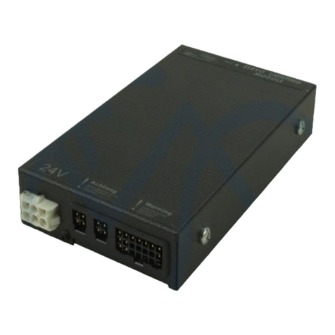
DX Power Module
(PMB, PMB1, PMB2, PMB-S)
Installation Manual
Order/Part Number for this Manual : GBK63824 issue 2
Important Notes
1. Read this Manual carefully before installing or operating your DX control system.
2. Due to continuous product improvement Dynamic reserves the right to update this Manual.
This Manual supersedes all previous issues which must not continue to be used.
3. Any attempt to gain access to or in anyway abuse the electronic components and
associated assemblies that make up the wheelchair control system renders the
Manufacturer’s Warranty void and the Manufacturer free from liability.
Contents
&RQWHQWV
 ,QWURGXFWLRQ  
PM Variants .............................................. 1
Example DX Systems ....................................... 2
A PM/PM1/PM2 System ............................... 2
A PM-S System ...................................... 3
 5HODWHG'RFXPHQWDWLRQ  
 ';3RZHU0RGXOH)HDWXUHV  
General Features .......................................... 5
Safety and Protection Features ................................ 6
Programmable Characteristics ................................ 7
 6SHFL LFDWLRQV  
Electrical ................................................ 8
PM Left and Right Motor Outputs ........................ 8
PM1LeftandRightMotorOutputs....................... 9
PM2 Left and Right Motor Outputs ....................... 9
PM-S Drive Motor Output ............................. 10
PM, PM1 and PM2 Left and Right Park Brake Outputs ...... 10
PM-S Left and Right Park Brake Outputs ................. 10
Mechanical .............................................. 11
Environmental ........................................... 12
Temperature and Humidity Specification ................. 12
Electromagnetic Compatibility Specification ............... 12
Standards .......................................... 12
Vibration Specification ............................... 12
 ,QVWDOODWLRQ  
General ................................................. 13
Mounting ............................................... 14
Mounting Rules ..................................... 14
General Mounting Considerations ....................... 15
PM Connection with the DX System .......................... 16
DXBUS Connections ................................. 16
DX Module Interconnection Topology Options ............ 17
Connections to other DX Modules ....................... 18
DXBUS Length and Voltage Drop Restrictions ............ 19
Contents
PM Connection with Motors and Park Brakes ................... 21
Motor and Park Brake Connector Pin Definitions ........... 21
Motor and Park Brake Connectors ....................... 22
Minimum Wire Sizes ................................. 22
PM-S Drive Motor Wiring ............................. 23
24V Park Brake Wiring (PM, PM1, PM2) ................ 24
12V Park Brake Wiring (PM, PM1, PM2) ................ 25
PM-S Park Brake Wiring .............................. 26
Park Brake Release Switches and Suppression Devices ...... 26
PM Connection with Batteries ............................... 27
BatteryConnector ................................... 27
Minimum Wire Sizes ................................. 28
Battery Wiring and Protection .......................... 28
 %DWWHULHVDQG&KDUJLQJ  
Battery Type ............................................. 30
Battery Charging ......................................... 30
 7HVWLQJ  
 3URJUDPPLQJ  
Introduction ............................................. 34
Default Programs ......................................... 34
Auto Download .......................................... 35
Programming Tools ....................................... 37
Dynamic Wizard .................................... 37
DX-HHP .......................................... 38
PM Wizard Programming .................................. 38
Introduction ........................................ 38
Parameter Specifications .............................. 40
Description of Parameters ............................. 41
PM HHP Programming .................................... 51
Initial Operation ..................................... 51
To Enable Technician Mode ........................... 52
Saving Changes ..................................... 53
Setting Veer Compensation ............................ 53
Setting Load Compensation ............................ 54
Contents
 'LDJQRVWLFVDQG)DXOW)LQGLQJ  
Flash Codes ............................................. 56
Limp Mode .............................................. 61
Wizard Diagnostics ....................................... 62
To View Diagnostics ................................. 62
Status Report ............................................ 62
To View Status Report ................................ 62
Chair Log ............................................... 63
To View Chair Log .................................. 63
Chair Log Messages .................................. 63
 (OHFWURPDJQHWLF&RPSDWLELOLW\(0&  
 0DLQWHQDQFH  
 6D HW\DQG0LVXVH:DUQLQJV  
Disclaimer .............................................. 69
 :DUUDQW\  
 6DOHVDQG6HUYLFH,Q RUPDWLRQ  
$SSHQGL[$$EEUHYLDWLRQV  
$SSHQGL[%3DUWV/LVW  
$QKDQJ&'HXWVFKVSUDFKLJH:DUQKLQZHLVH  
Contents
,QWURGXFWLRQ
1
 ,QWURGXFWLRQ
The DX Power Module (PM) is a DXBUS compatible module, which converts the
signals generated by a DX Remote into high current outputs. These outputs drive
the motors that control the wheelchair speed and direction. The combination of a
PM and DX Remote gives an exceptionally smooth, powerful and safe drive
system.
The PM is fully programmable to cater for a wide range of wheelchair types and
user needs. Correct installation and programming are essential to ensure optimum
performance and safety.
Note: This manual applies to DX-PMB, PMB1, PMB2 and PMB-S. The product
number is situated on the base of the unit.
This manual and others listed in section 2 must be read and understood. For more
information contact Dynamic Controls Ltd or an agent as listed in section 14.
309DULDQWV
Inadditiontothe standardPM,therearethreevariants:PM-S,PM1 andPM2. The
PM-S is used in DX Systems with only one drive motor, like many servo steered
wheelchair systems. The PM1 and PM2 differ from the PM only by their higher
current outputs. Unless otherwise stated, all featuresof the PM apply to the PM-S,
PM1 and PM2.
The PM-S has its two motor and Park Brake channels driven in parallel, for a
single motor output with twice the current of each channel of a standard PM - see
the motor and Park Brake wiring in the Installation section. Note that a standard
PM is recommended for use on servo steered wheelchairs with separate left and
right drive motors, rather than using a PM-S.
Where the PM has a 60A per channel output, the PM1 has 70A and the PM2 80A
per channel output.
 ,QWURGXFWLRQ
2
([DPSOH';6\VWHPV
$3030306\VWHP
A DX System with a standard PM, a PM1 or a PM2 may look like the following:
,QWURGXFWLRQ
3
$30 66\VWHP
A DX System using a PM-S will normally only have one drive motor, and will
contain a DX Servo Lighting Module (SLM) to drive the servo steering motor.
A PM-S system may look like the following :
 5HODWHG'RFXPHQWDWLRQ
4
 5HODWHG'RFXPHQWDWLRQ
A DX System may comprise between two and sixteen DX compatible modules
depending on the application. Each DX Module has its own Installation Manual
which describes the installation requirements of that particular module.
This Manual describes installation of the PM only and must therefore be read in
conjunction with :
The DX Remote Installation Manual for the DX Remote to be used withthe
PM in your installation;
The DX Hand Held Programmer (DX HHP) Manual;
The Dynamic Wizard Installation Manual / Online Help;
The Installation Manuals for all other DX Modules to be used in your
application.
Installation Manual Re-order Information
(Please quote this information when re-ordering this manual)
DX Power Module - GBK63824
';3RZHU0RGXOH)HDWXUHV
5
 ';3RZHU0RGXOH)HDWXUHV
*HQHUDO)HDWXUHV
The PM has the following general features:
Digital communications bus interface (DXBUS compatible), with remote
wake up and remote kill inputs via DXBUS;
Two identical DXBUS sockets with protected 12A RMS maximum battery
power supply;
Digital motor control;
Completelyprogrammableforparameterssuchasloadcompensation,motor
veer compensation, current limit level and dual or single Park Brakes;
Protected against external events such as:
- reverse battery
- battery under and over voltage
- overloaded motor or Park Brakes
- external short circuits
- stalled motor;
Extensiverangeofwheelchairsystemsafetyandprotectionfeaturessuchas:
- open circuit motor detection
- open and short circuit Park Brake detection
- controlled speed reduction to a stop if a fault is detected;
Electromagnetically compatible:
- low RF emissions
- low susceptibility to RF transmissions;
Environmentally compatible (sealed to IP54);
Built-in diagnostics with status LED and fault logging;
Compact, rugged enclosure with robust mounting points;
Approved by the German Safety Standards Authority TÜV.
 ';3RZHU0RGXOH)HDWXUHV
6
6DIHW\DQG3URWHFWLRQ)HDWXUHV
The PM has the following safety and protection features:
Detection of open circuit motors;
Detection of open or short circuit Park Brakes;
Battery under voltage protection with Battery Saver to prevent motor
chugging and to protect battery;
Thermal overload protection with progressive motor current roll back and
automatic recovery;
Over voltage shut down (protect outputs against damage if disconnected
battery; eg. while wheelchair is driving downhill, ie. motors generating);
Enhanceddownhillcontrolprovidingasmooth,controlledrollbackofspeed
should the battery voltage rise too high;
All outputs protected against over voltage transients and short circuits;
Isolate relay protects against reverse battery connections and prevents
runaway in event of H Bridge or Park Brake driver failure;
Detection of welded isolate relay contacts;
Detection of high resistance isolate relay contacts;
Dynamic braking in neutral;
Motor drive output monitoring;
Microcomputer watchdog protection;
Optional stalled motor time out;
Self test of current sensor and H Bridge at power up;
Hardware kill signal from DX Remote to prevent driving;
Watchdog, CPU, ROM and RAM testing at power up.
';3RZHU0RGXOH)HDWXUHV
7
3URJUDPPDEOH&KDUDFWHULVWLFV
The PM has the following programmable characteristics :
Maximum motor current;
Motor resistance (load compensation). Compensates for drive motor
inefficiencies. Correct compensation provides an even drive characteristic
over irregular driving conditions and terrain (eg on the flat, up hills, etc.);
Wheelchair veer compensation (for motor mismatch compensation);
Park Brake delay between the wheelchair stopping and the Park Brake
engaging;
Park Brake configuration (single or dual);
Motor stall time out duration and enable (on or off);
Rate of deceleration under fault conditions;
Left/Right Motor swap option to facilitate motor looming;
Left/RightMotorconnectorpolarityswaptoaccommodatemotorconnector
polarity options;
Optional thermal motor protection;
 6SHFL LFDWLRQV
8
 6SHFLILFDWLRQV
(OHFWULFDO
Applicable to both channels. Tamb = -25 to 50EC, VBAT = 24.0 V unless otherwise
specified.
Symbol Parameter Conditions Min Nom Max Units
VBAT Battery Voltage 18.0 24.0 32.0 V
VBSH "Battery saver" high
threshold Averaged. Battery
saver enabled 21.0 V
VBSL "Battery saver" low
threshold Averaged. Battery
saver enabled 18.0 V
PQQuiescent power Relay de-energised 2.0 5.0 W
PSBV Standby power PM "off" 15 30 mW
Tlim0 Thermal limit IMO =0 @ Tlim0 70 EC
IDXBUS DXBUS supply
current Case temp. 20EC12 A
30/HIWDQG5LJKW0RWRU2XWSXWV
Symbol Parameter Conditions Min Nom Max Units
fPWM PWM frequency 19.6 kHz
IMO Peak motor output
current Duration 15 seconds.
Initial case
temperature 20EC.
Current limit
programmed to 60A
54.0 60.0 66.0 A
IMO 15 minute continuous
motor current Tamb = 20°C 23.5 A
VMO Max. motor output
voltage Full conduction, IMO
= 10A 23.5 V
6SHFL LFDWLRQV
9
30/HIWDQG5LJKW0RWRU2XWSXWV
Symbol Parameter Conditions Min Nom Max Units
fPWM PWM frequency 19.6 kHz
IMO Peak motor output
current Duration 15 seconds.
Initial case
temperature 20EC.
Current limit
programmed to 70A
65 70 75 A
IMO 15 minute continuous
motor current Tamb = 20°C 24.5 A
VMO Max. motor output
voltage Full conduction, IMO
= 10A 23.5 V
30/HIWDQG5LJKW0RWRU2XWSXWV
Symbol Parameter Conditions Min Nom Max Units
fPWM PWM frequency 19.6 kHz
IMO Peak motor output
current Duration 15 seconds.
Initial case
temperature 20EC.
Current limit
programmed to 70A
75 80 85 A
IMO 15 minute continuous
motor current Tamb = 20°C 27.4 A
VMO Max. motor output
voltage Full conduction, IMO
= 10A 23.5 V
 6SHFL LFDWLRQV
10
30 6'ULYH0RWRU2XWSXW
Symbol Parameter Conditions Min Nom Max Units
fPWM PWM frequency 19.6 kHz
IMO Peak motor output
current * Duration 15 seconds.
Initial case
temperature 20EC.
Current limit
programmed to 120A
54 60 66 A
IMO 15 minute continuous
motor current * Tamb = 20°C 23.5 A
VMO Max. motor output
voltage Full conduction, IMO
= 20A 23.5 V
* = Output per motor connector
3030DQG30/HIWDQG5LJKW3DUN%UDNH2XWSXWV
Symbol Parameter Conditions Min Nom Max Units
IPBO Park Brake output
current VPBO #23.5V 1.0 A
VPBO Park Brake output
voltage IPBO = 0.5A 23.5 V
30 6/HIWDQG5LJKW3DUN%UDNH2XWSXWV
Symbol Parameter Conditions Min Nom Max Units
IPBO Park Brake output
current VPBO #23.5V 2.0 A
VPBO Park Brake output
voltage IPBO = 1A 23.5 V
6SHFL LFDWLRQV
11
184mm
208.5mm
45mm
125mm
M2 M1
198.5mm
0HFKDQLFDO
Size: 208.5 * 125 * 45 mm (excluding mounting brackets)
Weight: 1.1 kg
Mounting: Using 2 M5 socket cap screws through mounting lugs
198.5mm apart
Case material: Pressure die cast aluminium
Case finish: Epoxy powder coat
Case sealing: IP54, tamper proof, if mounted as per instructions
 6SHFL LFDWLRQV
12
(QYLURQPHQWDO
7HPSHUDWXUHDQG+XPLGLW\6SHFLILFDWLRQ
Parameter Min Max Units
Operating ambient temperature range -25 50 EC
Storage temperature range -25 70 EC
Operating and storage humidity 0 90 %RH
(OHFWURPDJQHWLF&RPSDWLELOLW\6SHFLILFDWLRQ
RF Emissions CISPR 11, Class B
ESD ISO7176, part 21
6WDQGDUGV
The PM controller has been designed to meet the requirements of prEN12184 :
1997 (pending).
9LEUDWLRQ6SHFLILFDWLRQ
120 minutes @ 4g random vibration without damage.
,QVWDOODWLRQ
13
 ,QVWDOODWLRQ
*HQHUDO
Installation of a DX Power Module and basic DX system normally comprises:
1. Mounting the PM.
2. PM Connection with the DX System.
3. PM Connection with Motors and Park Brakes.
4. PM Connection with Batteries.
5. Pre-testing.
6. Programming and re-testing
Compatibility with Power Wheelchairs
The model DX Series power wheelchair controller will function on those
wheelchairs equipped with the following specifications:
CMotor resistance from 0 to 0.5 ohms;
CMotor voltage from 20V to 30V;
CBatteries greater than 20Ah lead acid;
CPeak motor current 60A - 80A maximum per motor output
(model dependant);
C12V or 24V Park Brake;
(Note: 12V motors can be used if the controller is programmed to half speed).
 ,QVWDOODWLRQ
14
0RXQWLQJ
ThePMisdesignedtobemountedinanumberof orientations.To maintainsealing
to IP54, certain rules must be observed for the different mounting scenarios, as
follows :
0RXQWLQJ5XOHV
1. The vent hole area must be protected against direct splashing.
2. The mounting arrangement mustpreventwater accumulation underthevent
hole area.
,QVWDOODWLRQ
15
3. Ifmounting washers are used, they must be 30mmor greater in diameter for
stability.
4. If the PM is mounted with its connectors upward, the connector should be
shielded from water ingress and the cabling restrained such that water may
not run down the cables into the connector systems.
*HQHUDO0RXQWLQJ&RQVLGHUDWLRQV
The selected position and orientation should give the module maximum
mechanical and environmental protection. Avoid positions in which the
module or its wiring can be knocked or physically damaged or which are
exposed to splashing or other forms of abuse.
The length of high current cabling should be minimised. Aposition close to
the batteries and motors is favoured.
Anorientationandpositioninwhichthefinsareverticalandairflowthrough
the fins is unimpeded is preferred.
An orientation in which the PM Status LED is visible may be helpful.
Mounting the PM on a metal surface may assist heat conduction and give
better performance.
Whenall wiringiscompleted,it mustbe securelyfastenedto the wheelchair
frameto ensurethatinnormalconditionsthereis nostrainto theconnectors.
Once the position has been selected
fix the unit securely using two M5
socket cap screws with suitable
locking washers. Dimensions for hole
centres are as shown.
To fulfill ISO requirements, the left and right motor connections must be
short enough so that they can not be swapped by the wheelchair user.

This manual suits for next models

3

Other Dynamic Control Unit manuals

Dynamic DX-ECU User manual

Dynamic

Dynamic DX-ECU User manual

Dynamic DX2-GYRO Installation and operating instructions

Dynamic

Dynamic DX2-GYRO Installation and operating instructions

Dynamic DX 12V User manual

Dynamic

Dynamic DX 12V User manual

Dynamic DX-REMG91 User manual

Dynamic

Dynamic DX-REMG91 User manual

Dynamic DX User manual

Dynamic

Dynamic DX User manual

Popular Control Unit manuals by other brands

SMC Corporation IL211 Series instruction manual

SMC Corporation

SMC Corporation IL211 Series instruction manual

Cabletron Systems FRM user guide

Cabletron Systems

Cabletron Systems FRM user guide

WAGO 750-450 manual

WAGO

WAGO 750-450 manual

Hitachi HX-RIO3 Series user manual

Hitachi

Hitachi HX-RIO3 Series user manual

Fisher 377 instruction manual

Fisher

Fisher 377 instruction manual

mycom IMS20-210 user manual

mycom

mycom IMS20-210 user manual

Carrier Infinity SYSTXCCITC01-B owner's manual

Carrier

Carrier Infinity SYSTXCCITC01-B owner's manual

Häfele 633.03.298 quick start guide

Häfele

Häfele 633.03.298 quick start guide

Norbec IM4 operating instructions

Norbec

Norbec IM4 operating instructions

Kohler K-10668 Homeowner's guide

Kohler

Kohler K-10668 Homeowner's guide

Fermax LYNX SKYLINE Quick start manual

Fermax

Fermax LYNX SKYLINE Quick start manual

SIMCom Wireless Solutions SIM7600A-H user manual

SIMCom Wireless Solutions

SIMCom Wireless Solutions SIM7600A-H user manual

Beninca CP.MS4 operating instructions

Beninca

Beninca CP.MS4 operating instructions

Westlock 1100 Installation and setup manual

Westlock

Westlock 1100 Installation and setup manual

Allen-Bradley XM-124 user manual

Allen-Bradley

Allen-Bradley XM-124 user manual

Pilz PDP67 F 8DI ION operating manual

Pilz

Pilz PDP67 F 8DI ION operating manual

ZURN WILKANS PV-PRD quick start guide

ZURN

ZURN WILKANS PV-PRD quick start guide

Loctite 97135 Operation manual

Loctite

Loctite 97135 Operation manual

manuals.online logo
manuals.online logoBrands
  • About & Mission
  • Contact us
  • Privacy Policy
  • Terms and Conditions

Copyright 2025 Manuals.Online. All Rights Reserved.