Dynamix VC-M User manual

/VC-SDYNAMIX VC-MVDSL CO Converter
User’s Manual

VDSLCO(POINTTOPOINT) USER’SMANUALA.9
1
VDSL CO(POINT TO POINT) USER’S MANUAL
VDSL Point to Point Solution
The VDSL (Very High Data Rate DSL) networking solution delivers
cost-effective, high-performance broadband access to multiunit buildings
(hotels, apartment, and multi-tenant unit office buildings) and enterprise
campus environments such as manufacturing, educational campuses, and
medical facilities. VDSL technology dramatically extends Ethernet over
existing Category 1/2/3 wiring at speeds 10Mbps (full duplex) and distances
up to 1200 meters. The VDSL technology delivers broadband service on
the same lines as Plain Old Telephone Service (POTS), digital telephone,
and ISDN system. In addition, VDSL supports modes compatible with
asymmetric digital subscriber line (ADSL), allowing service providers to
provision VDSL to buildings where broadband services already exist.
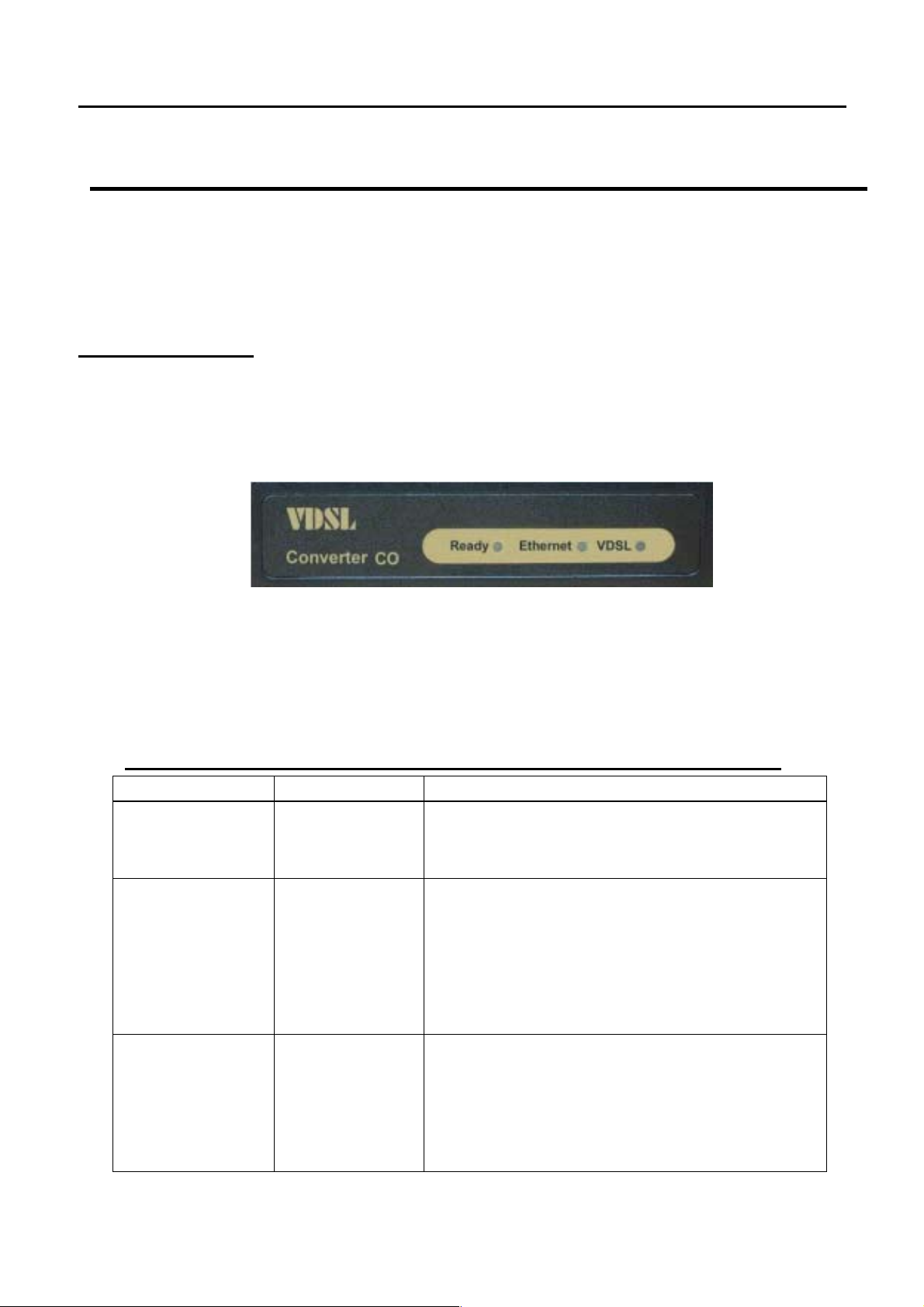
The VDSL solution includes VDSL Concentrator (VDSL switches)、VDSL
CO(Point to Point), and VDSL Converter for Customer Premise Equipment
(CPE) device.
The VDSL solution delivers everything needed to quickly deploy an
Ethernet-based network with the performance required to deliver
high-speed Internet access at much greater distances and drive services
like IP telephony and audio/video streaming. With this technology, a broad
range of customers can benefit from lower operating costs and rapid
deployment. This solution provides a RS-232C console port for monitoring
VDSL status and to configure speed.
This device is a CO side solution, and bridge between external Internet
backbone through a router for IP sharing and the building 110D telephone
rack or telephone box. It utilizes the available telephone wire to enable
high-speed Internet access to building residents.
VDSL converter uses the phone line networking technology endorsed by
the VDSL, and utilizes the already existing telephone wire to deliver 4/1,
5/10/15 Mbps Internet access on each RJ-11 port.
This gives users a low-cost, end-to-end solution and eliminates the need to
train installation teams on multiple systems.

VDSLCO(POINTTOPOINT) USER’SMANUALA.9
2
Foreword
This is an Ethernet to VDSL CO side adapter that enables high speed
internet access to building residents, campuses students and hotel guests
by connecting Ehternet equipped computers, set-top box or any internet
access device to the existing telephone wires.
The VDSL converter uses the phoneline networking technology endorsed
by the VDSL, an association of industry-leading companies for
in – networking focus on the existing telephone wire.
The Converter utilizes the already existing telephone wire to deliver
10Mbps internet access with no interference on the existing telephone
service. It allows user to make calls while access the internet on the
same wire simultaneously. It even allows staying connected 24 hours on
internet connections, thus, eliminating dial up prior to internet access.
The Converter is simple to install and use. One RJ-45 Ethernet connects
to a Router, Ethernet Switch or to LAN card. The RJ11 ports available to
connect to any existing modular phone jack.
There are two RJ-11 jack on the Converter to provide a phone extensions.
No software installation makes the converter highly compatible with
different operating system ( Windows, Linux, Apple….etc).

VDSLCO(POINTTOPOINT) USER’SMANUALA.9
3
VDSL CO CONVERTER
Contents
1. Unpacking Information
Check List ---------------------------------------------------- 4
2. Installation
Hardware Installation -------------------------------------- 5
Pre-Installation Requirements --------------------------- 5
General Rules ----------------------------------------------- 6
Connecting the Converter -------------------------------- 6
Connecting the RJ-11/RJ-45 Ports --------------------- 7
3. Hardware Description
Front Indicators---------------------------------------------- -9
Rear Connectors -------------------------------------------- 10
Left Side Connector ---------------------------------------- 10
Power On ----------------------------------------------------- 10
4. Configuration Software Description ---------------- 11
5. Glossary------------------------------------------------------ 26
6. Applications------------------------------------------------- 27
Application for Home networking ----------------------- 27
7. FCC/CEWarning------------------------------------------ 40
8. Warranty----------------------------------------------------- 41
Appendix A Cable Requirement ---------------------------------- 28
Appendix B Product Features & Specifications ------------ 30
Appendix C Trouble Shooting ------------------------------------ 32
Appendix D Speed Change Quick Guide ----------------------35
Appendix E Compliance and Safety Information----------- 37

VDSLCO(POINTTOPOINT) USER’SMANUALA.9
4
1. Unpacking Information
Check List
Carefully unpack the package and check its contents against the checklist.
Package Contents
VDSL CO x 1
Four plastic feet x 4
Diskette (User Manual & utility) x 1
AC To DC Power Adapter x 1
Ethernet Straight-through cable x 1
RJ-11 cable x 1
RJ-45 To D-SUB Cable x 1
Please inform your dealer immediately for any missing items, or damaged
parts. If possible, retain the carton, including the original packing
materials.
Use them to repack the unit in case there is a need to return for repairing.

VDSLCO(POINTTOPOINT) USER’SMANUALA.9
5
2. Installing the Converter
Hardware Installation
This chapter describes how to install the converter and establishes
network connections. You may install the converter on any level
surface (e.q, a table or shelf). However, please take note of the
following minimum site requirements before you begin. Stick the 4
plastic feet at the bottom to avoid scratches.
Pre-installation Requirements
Before you start the actual hardware installation, make sure you can
provide the right operating environment, including power requirements,
sufficient physical space, and proximity to other network devices that
are to be connected. Verify the following installation requirements:
Power requirements: DC 5V/1A or above
The converter should be located in a cool dry place, with at least
10cm/4in of space at the front and back for ventilation.
Place the Converter out of direct sunlight, and away from heat
sources or areas with a high amount of electromagnetic
interference.
Check if network cables and connectors needed for installation are
available

VDSLCO(POINTTOPOINT) USER’SMANUALA.9
6
General Rules
Before making any connections to the converter, note the following rules:
Ethernet Port (RJ-45)
All network connections to the Converter Ethernet port must be
made using Category 5 UTP for 100Mbps; Category 3,4 UTP for
10Mbps
No more than 100 meters of cabling may be use between the MUX
or HUB and an end node.
VDSL Port (RJ-11)
All Home network connections to the RJ-11Port made using 24~26
Gauge phone wiring.
We do not recommend using 28 Gauge or above phone line.
Connecting the Converter
The converter has one Ethernet port which support connection to
Ethernet operation. The devices attached to these ports must support
auto-negotiation or 10Base-T OR 100Base-TX unless they will always
operate at half duplex.
Use any of the Ethernet ports to connect to devices such as NIC,
Switch, bridge or router. You can also connect to another compatible
converter to an RJ-45 port on the other device.
The RJ11 Line port are use to connect to the wall RJ-11 modular
socket which is connect to VDSL CPE converter side (Point to point
solution)
The RJ11 Phone port of the converter can connected to a telephone
and a computer sharing one telephone wire for making calls and
accessing the internet at the same time.

VDSLCO(POINTTOPOINT) USER’SMANUALA.9
7
Connecting the RJ-11/RJ-45 Ports
1. The Converter’s RJ-11 ports support the transmission of data up
to 4/1, 5/10/15Mbps across existing phone wiring, without
interfering with standard voice transmissions, easy-to-use does
not require the installation of any additional wiring. Every RJ-11
modular phone jack in the home can become a port on the LAN.
Networking devices can be installed on a single telephone wire
that can span within 1.9/1.5/1.2/1km (depend on speed) between
the two farthest points. (Figure 1.0).
2. VDSL CO Converter has embedded Splitter between every
VDSL side (Line) and POTS (Phone) side. It permit you can
delivers broadband service on the same lines as Plain Old
Telephone Service (POTS), PBX, ISDN traffic and VDSL Signal.
Figure 1.0 VDSL Point to Point application

VDSLCO(POINTTOPOINT) USER’SMANUALA.9
8
1. The RJ-11 port support 4/1,5/10/15 Mbps connections. When
inserting a RJ-11 plug, be sure the tab on the plug clicks into
position to ensure that it is properly seated.
2. Do not plug a RJ-11 phone jack connector into the Ethernet port
(RJ-45 port). This may damage the converter Instead; use only
twisted-pair cables with RJ-45 connectors that conform to Ethernet
standard.
Notes:
1. Be sure each twisted-pair cable (RJ-45) does not exceeds 100
meters (333 feet).
2. RJ-11 port use 24 ~ 26 gauge phone wiring, we do not
recommend 28 gauge or above.
3. We advise using Category 3,4,5 cable for Cable
Modem or Router connections to avoid any confusion or
inconvenience in the future when you upgrade attached
to high bandwidth devices.

VDSLCO(POINTTOPOINT) USER’SMANUALA.9
9
3.Hardware Description
This section describes the important parts of the converter.
It features the front indicators and rear connectors.
Front Indicators
The following figure shows the front panel.
Figure Chapter 2.2 Front Indicators
At a quick glance of the front panel, it is easy to tell if the CO
converter has power, if it has signal from its Ethernet RJ-45 port and
if there is phone line signal on RJ-11port
LED Description and Operation. The Converter has three LED indicators.
LEDs Status Descriptions
Ready
(Ready LED)
Steady
Green
It will light up (ON) to show that the
product is power good, and system reset
OK.
Ethernet
(Ethernet LED)
Steady Green
Flashing
(LINK/ACT)
Each RJ45 station port on the Ethernet is
assigned an LED light for monitoring port
“Good Linkage”. LED is normally OFF
after the power on operation, but will light
up steadily to show good linkage and
f
lashing to show data transmission.
VDSL
(VDSL LED) Steady Green
RJ11 station port on the VDSL is assigned
an LED light for monitoring port “Good
Linkage”. LED is normally OFF after the
power on operation, but will light up
steadily to show good linkage.

VDSLCO(POINTTOPOINT) USER’SMANUALA.9
10
Rear Panel
The following figure shows the rear connectors
Figure Chapter 2.3 Rear Connectors
Table Converter Rear Connectors
Connectors Description Type
Line For connecting to the VDSL Modem Using a
RJ-11 cable RJ-11
Phone For connecting to the telephone or Fax
、ISDN modem RJ-11
Ethernet For connecting to a Ethernet equipped device RJ-45
Left side view
The following figure shows the left side connectors. You can adjust
VDSL Speed and Monitor VDSL status from console (see chapter 4).
Figure Chapter 2.4 Left side Connector
Table Converter Rear Connectors:
Connector Description Type
Console port For connecting to PC with RS-232 serial port
over a RJ-45 To D-SUB Cable RJ-45
Power On
1. Check the adapter is properly connected.
2. Verify the power LED is steadily on.

VDSLCO(POINTTOPOINT) USER’SMANUALA.9
11
4 Configuration Software Description
4.1 Start-up Dialog
When the software is started, the user has to adjust the COM port setting
for which is connected to.
Figure 4.1 shows startup dialog.
Figure 4.1 Startup Dialog4.2 Configuration Software Pages

VDSLCO(POINTTOPOINT) USER’SMANUALA.9
12
4.2.1 General Settings Page
The general settings page allows basic settings. Both, local and remote
modem (if available and synchronized) can be addressed by this window.
Figure 4.2 shows the general settings page.
Figure 4.2 General Settings Page

VDSLCO(POINTTOPOINT) USER’SMANUALA.9
13
Following functions are supported on the General Settings page:
• Modem Type Display: Indicates which modem type (LT or NT) is the
local and remote modem.
• Reset: Performs a soft reset of the modem. After a soft reset, the
10BaseS-D is held in reset state for 256 clocks.
• Local Loop back: Returns data from the Tx port of the 10BaseS-D to the
Rx port of the 10BaseS-D. The transmitted data to the line is not
guaranteed when the local loop back is activated. This feature is not
supported on the far-end modem, since this would bring down the link
.• Line Loop back: Connects the output port of the VDSL TC-layer to the
TC-layer input. This loop back contains the Ethernet interface, the
scrambler, the Reed Solomon block, interleaver, framer and synchronizer.
• Turn transmitter on/off: This button turns the transmitter on/off in case a
VDSL link is not established. This feature serves for test purposes, e.g
monitor the spectrum with a spectrum analyzer.
• Activation disable/enable: This button enables the user to enable or
disable the VDSL link

VDSLCO(POINTTOPOINT) USER’SMANUALA.9
14
4.2.2 Link Configuration Page
The Link Configuration window shown in Figure 4.3 allows access to the
PMD (Physical Media Dependent) registers of the VDSL. Both, local and
remote modem (if available and synchronized) can be addressed by this
window.
Figure 4.3 Link Configuration Page

VDSLCO(POINTTOPOINT) USER’SMANUALA.9
15
The following functions are available within the Link Configuration page:
• Customized Settings(Not Release): If this option is selected, the user
has access to the whole bandwidth of adjustable constellations and
interpolations as well as the carrier frequencies. So he can easily find the
appropriate line rate for his special application.
• Use Recommendations: In this option the user can select a couple of
approved constellations, interpolations and carrier frequencies to change
the line rate of the modem.
We support the following modes:
4/1 M asymmetrical rate (up to 1900 meters)
5 M symmetrical rate (up to 1500 meters)
10 M symmetrical rate (up to 1200 meters)
15 M symmetrical rate (up to 1000 meters)
Change Speed procedures:
a. Connecting both VDSL CO and VDSL CPE.
b. Make sure VDSL CO has already connected to VDSL CPE,
please check both VDSL LEDs are light up.
c. Select the Upstream and Downstream speed mode (4/1M, 5 M /
10 M / 15 M)
d. Click “Write & Update” to confirm the settings
e. The VDSL port LED will be link down temporarily about 30~60
seconds.
f. Then the VDSL link LED will be re-linked up. It means that the
new speed mode has been changed successfully.
Note. Manufacturing default threshold is on 10Mbps mode.
• Line Rate Throughput:
4/1M Line Rate=
4.17/1.56 Mbps
5M Line Rate= 6.25 Mbps
10M Line Rate=12.5 Mbps
15M Line Rate=16.67 Mbps

VDSLCO(POINTTOPOINT) USER’SMANUALA.9
16
4.2.2.1 Write-Update Message Box
After pressing button “Write & Update” the message box shown in
Figure 4.4 appears.
Figure 4.4 Write and Update Message Box
Pressing “OK” causes the following actions:
• If a VDSL link is established the software changes all registers in the
remote modem(via the VOC) and then the in the local modem.
• If no VDSL link is established the changes are only applied to the local
modem Pressing “CANCEL” closes the box without changes.

VDSLCO(POINTTOPOINT) USER’SMANUALA.9
17
4.2.2.2 Read Message Box
After pressing button “Read”, System will show current Downstream and
Upstream status of Line Rate, Interpolation, Constellation and Carrier
Frequency.
4.2.3 VDSL PHY Status Page
The VDSL PHY Status page shown in Figure 4.5 represents the current
link status of the local modem. This window is refreshed each five seconds.
Figure 4.5 VDSL PHY Status

VDSLCO(POINTTOPOINT) USER’SMANUALA.9
18
The status page shows the following values:
• SNR of Received Signal: The SNR of the received signal is calculated
from the parameters found in the PMD layer. The SNR calculation depends
on the QAM constellation of the received signal.
Followings are the good SNR readings(db) for each of the standard
line rates in VDSL CO:
4/1M >=19db
5M >=25db
10M >=25db
15M >=37db
• Mean Square Error: The mean square error is an indication of the
symbol error rate. Its calculation depends on the QAM constellation and the
SNR of the received signal
• Corrected RS Error(s): This field gives the number of corrected Reed
Solomon errors per second. It is an indication of the bit error rate on the line
due to disturbers.
• Transmit Power: This field shows the actual transmitted power level. On
RT modems with PBO enabled this value may be different from the
minimum and maximum PSD level adjusted on the Link Configuration Page
• Full Constellation Link: Full constellation link is working and the modem
can transmit and receive data
• Reduced Constellation Link: The modem has synchronized in reduced
constellation(QAM4) only. In this state the VDSL Operating Channel (VOC)
is working and the VOC channel can be used to re-configure the link.
• TC Synchronized: Indicates that the transmission convergence layer (TC)
is synchronized. VDSL frame acquisition is working and the modem is in
SYNC state

VDSLCO(POINTTOPOINT) USER’SMANUALA.9
19
• Ethernet Encapsulation Sync: Indicates that the Ethernet data path
machine has synchronized. In this state payload data transmission is
working.
• Remote I/F Synchronized: Indicates that the remote data interface is
synchronized.
• Signal Detected: Indicates that a signal is detected after the
Analog-to-Digital Converter (ADC).
• Micro Interruption occurred: Indicates that a micro interruption (<10ms)
has occurred.
• AGC Converged: Indicates that the automatic gain control (AGC) has
converged.
• Timing Converged: Indicates that the timing acquisition function is
converged. This indication is only active in RT configuration.
• ADC Saturation: Indicates a saturation of the ADC due to strong noise.
• Link Fail Counter: Counts the VDSL link failures since the first
synchronization.
This manual suits for next models
1
Table of contents
Other Dynamix Media Converter manuals
Popular Media Converter manuals by other brands

CEL-MAR
CEL-MAR ADC-216-U user manual

RME Audio
RME Audio ADI-8 DS user guide

Danfoss
Danfoss iC7 Series installation guide

Musical Fidelity
Musical Fidelity V-LINK 192 instructions

exaSound
exaSound e68 owner's manual

Jefferson Professional Tools & Equipment
Jefferson Professional Tools & Equipment JEFKVS04 user guide