1. GENERAL INFORMATION
This user manual provides all necessary information for the operation and the efficient and safe use of the IS-6000 Doppler
flow meter. It contains important information on product identification, storage, installation, commissioning, operation,
maintenance and disposal of the device. Before putting the device into operation, read this user manual carefully. To prevent
possible injuries to the user and damage, use the device only for the intended use described below. Always keep this
document handy in the vicinity of the device! If you do not understand the contents of this document, contact the
manufacturer. In no case may the manufacturer be held reliable for any damage or injury caused by misunderstanding
of the information.
1.1. Copyright
All rights reserved. The contents and works in this document are subject to German copyright. Contributions from third
parties are identified as such. No part of this documentation may be reproduced in any form, stored or transferred, neither
electronically, mechanically, photo-technically, by recording on data media or otherwise, as long as no expressly written
authorization from the publisher is present.
1.2. Data Protection and Security
All data should be backed-up prior to the installation of any peripheral storage device. The manufacturer will not be
responsible for any loss of data resulting from the use or misuse of this or any other product from the manufacturer. Data
security is given by personated login with username and password. Data will be saved on the server with appropriate security
measures for protection against data loss, data abuse and unauthorized data modifications.
There are inherent security risks in transmitting data via the internet. It is not possible to safeguard completely against
unauthorized access by third parties.
The use of contact data published within the framework of the imprint obligation by third parties for the transmission of not
expressly requested advertising and information material is hereby expressly rejected.
1.3. Liability
In case of inappropriate or unintended use, no liability for the proper function of the device can be assumed. Improper
installation and operation of the device will void the warranty. The manufacturer has made every effort to assure the accuracy
of the contents of this manual and the software. However, the manufacturer can offer no guarantee that the information
provided is accurate and/or free of error. The information provided in this manual is subject to change without notice at any
time. The manufacturer reserves the right to alter designs, layouts or software without prior notification and will not be liable
in any way for possible consequences of such changes.
1.4. EU Conformity Declaration
The manufacturer hereby declares that this product complies with Directive 2014/30/EU, 2014/35/EU, 014/53/EU, 2014/65/EU.
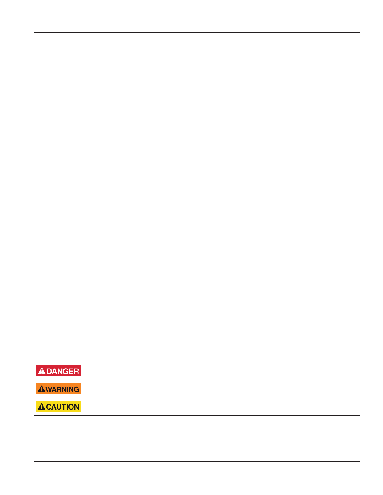
1.5. Warnings and Safety Symbols
Depending on the hazard level, warnings are displayed as follows.
Immediate danger. Indicates a potentially or imminently hazardous situation which, if not avoided, will
result in death or serious injury.
Medium risk. Indicates a potentially or imminently hazardous situation which, if not avoided, could result
in death or serious injury.
Minor risk. Indicates a potentially hazardous situation that may result in minor or moderate
injury or damage.
MPORTANTI
Important handling instruction. Indicates a situation which, if not avoided, may cause damage to the device. Information that
requires special emphasis.
OTE:NThis symbol indicates helpful notes and information for handling the device.
User Manual
Page viiMarch 2021 HYB-UM-03155-EN-03