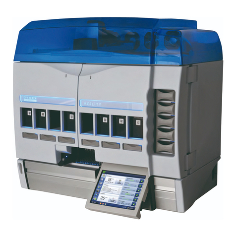
Dynex DSX User manual

DSX™ Automated ELISA System
Service Manual
IMPORTANT: Please read this manual carefully before servicing
or adjusting the system.

Revision History
Revision Date:
July 2004
April 2005
Notice: The DSX™ Automated ELISA System is covered by a warranty (a copy of which is
enclosed in this manual). The customer is required to perform routine maintenance as
described in the user’s manual on a periodic basis to keep the warranty in effect.
DYNEX Technologies reserves the right to make technical improvements to this equipment
and documentation without notice as part of a continuous program of product development.
This manual supersedes all previous editions.
The material included in this manual is provided to assist service engineers in the
maintenance and repair of the DSX™ Automated ELISA System. It is assumed that the
individual using this manual has sufficient training in the service of analytical instrumentation
and is aware of the potential hazards including (but not limited to) electrical hazards, chemical
hazards and mechanical hazards.
If this manual is provided to an end user, it is with the understanding that the material
included herein is proprietary to DYNEX Technologies, Inc. The user may not provide this
material to a third party without the written permission of DYNEX Technologies.
Questions or comments regarding the content of this manual can be directed to:
DYNEX Technologies, Inc.
14340 Sullyfield Circle
Chantilly VA 20151-1683 USA
Phone: (800) 288-2354 (USA only)
(703) 631-7800
Fax: (703) 803-1441
Part No. 91000090, Revision B
DSX™ Automated ELISA System is a trademark of DYNEX Technologies, Inc.
This manual is published by DYNEX Technologies, Inc.
2001, 2005 This document is the copyright of DYNEX Technologies, Inc. and must not be
copied or reproduced in any form without prior consent.
DYNEX Technologies reserves the right to make technical improvements to this equipment
and documentation without prior notice as part of a continuous program of product
development. This manual supersedes all previous editions.

Preface
Preface
The purpose of this manual is to enable a qualified field service engineer to carry out routine
maintenance and minor repairs on the DYNEX Technologies DSX™ Automated ELISA
System. In general, the service engineer is expected to make repairs, replace modules and
replace electromechanical subassemblies. Printed circuit boards and a few other components
are typically replaced as major subassemblies.
This manual is provided to complement the DSX™ Automated ELISA System Operator’s
Manual (Part No. 91000060). In some instances, references will be made to the Operator’s
Manual.
In most instances, the supplier of the reagent kit will install the unit. Detailed installation
information is provided in Chapter 2 of the Operator’s Manual.
Defective subassemblies may be returned to DYNEX Technologies or your DYNEX
Technologies distributor, where comprehensive repair facilities are available.
The service engineer should contact the local DYNEX Technologies service office for
additional information.
DSX™ System Service Manual i

Warnings and Safety Precautions
The DYNEX Technologies DSX™ Automated ELISA System is designed to meet all relevant
safety codes. The service engineer should note the following points:
1 If any fluid contains an organic solvent, make sure that the laboratory is well
ventilated, so that a build-up of solvent cannot occur. In addition, avoid open
flames and sparks.
2 The system should be plugged into a power line that is connected to a true
ground. Make certain that all internal grounding cables are connected.
3 The reagents, wash solution etc., may contain compounds that may be
hazardous. Always wear safety glasses and protective clothing when working with
the washing solution or when the washer is operating (when testing the system, it
is recommended that deionized water be used).
4 The microplates and the waste solution may contain materials that present a
toxicological, radioactive or biological hazard. If the system is returned to a
DYNEX Technologies service facility, make certain that a "Certification of
Decontamination" is submitted before working on the unit.
5 Line voltage is present in the Power Supply printed circuit board and lower
voltages are present in other components. If the power must be on during testing,
take care to avoid contacting exposed components.
6 The cover interlock is provided as a safety feature so that the unit will not function
when the cover is in the upright (open position). If the interlock is disabled, there
is the possibility for bodily injury from rapid movements by the X, Y, and Z
assemblies. Care should be taken when operating the unit in this state.
ii DSX™ System Service Manual

Table of Contents
Table of Contents
Chapter 1 Introduction to the DSX™ Automated ELISA System ............................................. 1-1
1.1 Overview .............................................................................................................. 1-1
1.2 Functional Description and Features................................................................... 1-2
1.3 Steps in an Analysis ............................................................................................ 1-3
1.4 Major Components of the System ....................................................................... 1-4
1.4.1 Work Area................................................................................................ 1-4
1.4.2 Ambient Drawer and Plate Holders......................................................... 1-5
1.4.3 Pipette Module ........................................................................................ 1-6
1.4.4 Incubator Modules................................................................................... 1-7
1.4.5 Wash Module........................................................................................... 1-8
1.4.6 Wash Buffer Containers .......................................................................... 1-9
1.4.7 Waste Containers.................................................................................. 1-10
1.4.8 Absorbance Module .............................................................................. 1-11
1.4.9 System Cover ........................................................................................ 1-12
1.5 Application Software .......................................................................................... 1-13
1.6 Contents of this Manual ..................................................................................... 1-14
Chapter 2 Installation....................................................................................................................2-1
2.1 Overview .............................................................................................................. 2-1
2.2 Receipt of the System.......................................................................................... 2-1
2.3 Power Requirement ............................................................................................. 2-1
2.4 Locating the System in the Laboratory ................................................................ 2-1
2.5 Loading the Application ....................................................................................... 2-2
2.6 Initializing Communication ................................................................................... 2-4
2.7 Loading the Desired Assay.................................................................................. 2-8
Chapter 3 Maintenance and Introduction to Service................................................................. 3-1
3.1 Overview .............................................................................................................. 3-1
3.2 User Maintenance................................................................................................ 3-2
3.2.1 Maintenance Schedule............................................................................ 3-2
3.3 Cleaning and Decontamination............................................................................ 3-4
3.3.1 Cleaning the System ............................................................................... 3-4
3.4 Servicing the DSX Automated ELISA System..................................................... 3-5
3.4.1 Servicing Modules ................................................................................... 3-5
3.4.2 Servicing Non-Modular Components ...................................................... 3-5
3.5 Post-Service Checkout Protocol .......................................................................... 3-6
3.5.1 Role of the Post Service Checkout Protocol ........................................... 3-6
3.5.2 Power Down the System ......................................................................... 3-6
3.5.3 Workspace Calibration ............................................................................ 3-6
3.5.4 Module Calibration ................................................................................ 3-10
3.5.5 Drawer Calibration................................................................................. 3-11
3.5.6 Manual Adjustment of the Module Calibration ...................................... 3-12
3.5.7 Cycle Test.............................................................................................. 3-15
3.5.8 Tip Alignment Test ................................................................................ 3-15
3.5.9 Manual Wash Plate Test ....................................................................... 3-16
3.6 Returning Components...................................................................................... 3-18
DSX™ System Service Manual iii

Table of Contents
Chapter 4 Troubleshooting ...........................................................................................................4-1
4.1 Overview...............................................................................................................4-1
4.2 Initialization ...........................................................................................................4-2
4.2.1 The Instrument Fails to Power up ............................................................4-2
4.2.2 The System Cannot Communicate with the Computer............................4-3
4.2.3 General Information..................................................................................4-3
4.2.4 Checking the Communication Link...........................................................4-4
4.2.5 Incorrect Password...................................................................................4-5
4.3 System Problems..................................................................................................4-6
4.3.1 Communication Problems ........................................................................4-6
4.3.2 Problems in a Specific Module.................................................................4-9
4.4 Application Problems..........................................................................................4-10
Chapter 5 Manual Operation of the System ................................................................................5-1
5.1 Overview...............................................................................................................5-1
5.2 Manual Control Operations...................................................................................5-2
5.2.1 Selecting the Desired Operation ..............................................................5-2
5.2.2 Performing the Operation.........................................................................5-3
5.2.3 Testing the Reader...................................................................................5-3
5.2.4 Testing the Drawer ...................................................................................5-4
5.2.5 Incubators.................................................................................................5-5
5.2.6 Washer .....................................................................................................5-6
5.2.7 Plate Movement .......................................................................................5-8
5.2.8 Arm...........................................................................................................5-9
5.2.9 Advanced ...............................................................................................5-11
5.2.10 Testing..................................................................................................5-12
5.3 Washing A Plate .................................................................................................5-13
Chapter 6 The Pipette Module/XYZ Drive ....................................................................................6-1
6.1 Overview...............................................................................................................6-1
6.2 The X-Drive and Y-Drive ......................................................................................6-3
6.2.1 General Design of the Drive Mechanisms ...............................................6-3
6.2.2 Command Types ......................................................................................6-7
6.2.3 Top Level Functional Design....................................................................6-8
6.2.4 Hardware Considerations.........................................................................6-9
6.3 The Z-Drive and the Pipette Module...................................................................6-11
6.3.1 General Design of the Drive Mechanisms .............................................6-11
6.3.2 Command Types ....................................................................................6-13
6.3.3 Top Level Functional Design..................................................................6-15
6.3.4 Hardware Considerations.......................................................................6-15
6.4 Serial Communication with the Controller ..........................................................6-16
Chapter 7 Replacing Components - Pipette/XYZ Axis Assemblies ..........................................7-1
7.1 Overview...............................................................................................................7-1
7.2 Troubleshooting ....................................................................................................7-2
7.3 Replacing the Pipette Assembly...........................................................................7-4
7.4 The Z-Drive Assembly ........................................................................................7-16
7.4.1 Removing the Z-Drive Assembly............................................................7-16
7.4.2 Replacing the Z-Drive Spring Assembly ................................................7-17
7.4.3 Removing and Replacing the Z-Drive Encoder......................................7-20
7.4.4 Replacing the Z-Drive Optointerrupter Assembly ..................................7-21
7.4.5 Replacing The Z-Drive Belt ....................................................................7-22
iv DSX™ System Service Manual

Table of Contents
7.4.6 Replacing the Z Motor ........................................................................... 7-27
7.4.7 Replacing the Idler Assembly................................................................ 7-28
7.4.8 Replacing the Z Axis Transition Board.................................................. 7-30
7.5 The Y-Drive Assembly ....................................................................................... 7-31
7.5.1 Removing the Y-Drive Assembly .......................................................... 7-31
7.5.2 Removing the Y-Transition Printed Circuit Board ................................. 7-32
7.5.3 Replacing the Encoder .......................................................................... 7-33
7.5.4 Removing the Y-Axis Drive Belt ............................................................ 7-35
7.5.5 Removing the Y Optointerrupter............................................................ 7-40
7.5.6 Removing the Pulley ............................................................................. 7-41
7.5.7 Removing the Y Axis Motor................................................................... 7-41
7.5.8 Replacing the Idler Pulley...................................................................... 7-42
7.6 The X Axis Drive Assembly ............................................................................... 7-43
7.6.1 Replacing the Optointerrupter ............................................................... 7-43
7.6.2 X-Axis Motor.......................................................................................... 7-43
7.6.3 Replacing the Encoder .......................................................................... 7-44
7.6.4 Removing the Pulley from the X-Drive Motor........................................ 7-46
7.6.5 Replacing the X Idler Pulley Assembly ................................................. 7-47
7.6.6 Adjusting the X-, Y-, or Z- Motor Pulley and Idler Pulley....................... 7-50
7.6.7 Replacing the X Transition Printed Circuit Board.................................. 7-51
7.6.8 Replacing the X-Drive Belt .................................................................... 7-53
7.7 Spare Parts and Jigs ......................................................................................... 7-57
7.7.1 Z-Drive Assembly (13001440)............................................................... 7-57
7.7.2 Y-Drive Assembly (13001430) .............................................................. 7-58
7.7.3 X-Drive Assembly (13001420) .............................................................. 7-59
7.7.4 Jigs ........................................................................................................ 7-59
Chapter 8 The Incubator Module ................................................................................................. 8-1
8.1 Overview .............................................................................................................. 8-1
8.2 Design of the Incubator Module........................................................................... 8-1
8.3 Electrical/Control Considerations......................................................................... 8-2
8.4 Operational Activities for the Incubator Module................................................... 8-4
Chapter 9 Servicing the Incubator Module................................................................................. 9-1
9.1 Routine Maintenance/Service Procedures .......................................................... 9-1
9.2 General Troubleshooting ..................................................................................... 9-1
9.3 Removing External Components......................................................................... 9-3
9.3.1 The Top Cover......................................................................................... 9-3
9.3.2 The Bottom Cover ................................................................................... 9-4
9.3.3 The Front Bezel....................................................................................... 9-5
9.3.4 Removal/Replacement of the Plate Carrier Door.................................... 9-6
9.4 Repairing/Replacing Internal Components.......................................................... 9-9
9.4.1 Removal/Replacement of the Main Circuit Board ................................... 9-9
9.4.2 Replacing the Top Heater Plate Assembly ........................................... 9-11
9.4.3 Removal of the Eject Sensor................................................................. 9-13
9.4.4 Removing the Position Sensor .............................................................. 9-14
9.4.5 Removal/Replacement of the Drive Belt ............................................... 9-15
9.4.6 Removing the Plate Carrier Motor......................................................... 9-17
9.4.7 Removal/Replacement of the Plate Carrier Assembly.......................... 9-19
9.4.8 Replacement of Lower Heater Assembly.............................................. 9-21
9.4.9 Removal/Replacement of Locking Lever/Pivot/Spring.......................... 9-23
9.4.10 Removal/Replacement of the Plate Carrier Bearings ......................... 9-25
DSX™ System Service Manual v

Table of Contents
9.5 Spare Parts.........................................................................................................9-26
9.6 Jigs......................................................................................................................9-26
Chapter 10 The Reader Module ....................................................................................................10-1
10.1 Overview .........................................................................................................10-1
10.2 Design of the Optical Module ..........................................................................10-1
10.2.1 General Characteristics........................................................................10-1
10.2.2 Optical Considerations .........................................................................10-2
10.2.3 Electrical/Control Considerations .........................................................10-3
Chapter 11 Servicing the Reader Module....................................................................................11-1
11.1 Routine Maintenance/Service Procedures......................................................11-1
11.1.1 Replacing the Lamp .............................................................................11-1
11.1.2 Removing and/or Installing a Filter.......................................................11-2
11.2 Troubleshooting the Reader Module...............................................................11-4
11.2.1 Error Messages upon Power up...........................................................11-4
11.2.2 General Troubleshooting......................................................................11-6
11.2.3 Measurement Errors.............................................................................11-9
11.3 Removing External Components ..................................................................11-11
11.3.1 The Top Cover ...................................................................................11-11
11.3.2 The Bottom Cover ..............................................................................11-12
11.3.3 The Front Bezel..................................................................................11-13
11.3.4 Removal/Replacement of the Plate Carrier Door...............................11-14
11.4 Repairing/Replacing Internal Components ...................................................11-17
11.4.1 Removal/Replacement of the Main Board .........................................11-17
11.4.2 Removal/Replacement of the Plate Carrier Motor .............................11-18
11.4.3 Removal/Replacement of the Drive Belt ............................................11-21
11.4.4 Removal/Replacement of the Plate Carrier Assembly.......................11-22
11.4.5 Removal/Replacement of Locking Lever/Pivot/Spring.......................11-23
11.4.6 Removal/Replacement of the Plate Carrier Bearings ........................11-24
11.4.7 Installing the Plate Carrier..................................................................11-25
11.4.8 Removal/Replacement of the Idler Bearings .....................................11-26
11.4.9 Removal/Replacement of the Fiber Optic Bundle..............................11-28
11.4.10 Removal/Replacement of the Optics Cube......................................11-29
11.4.11 Removal/Replacement of the Lens Holder ......................................11-30
11.4.12 Removal/Replacement of the Optics in the Lens Bracket ...............11-31
11.4.13 Removal/Replacement of the Lamp Holder .....................................11-32
11.4.14 Removal/Replacement of the Optics Cube Fan...............................11-33
11.4.15 Removal/Replacement of the Filter Wheel ......................................11-34
11.4.16 Removal/Replacement of the Filter Motor .......................................11-35
11.4.17 Removal/Replacement of the Filter Switch ......................................11-36
11.4.18 Removal/Replacement of the Slide Blocks ......................................11-37
11.4.19 Removal/Replacement of the Plate In and Out Sensors .................11-38
11.4.20 Removal of the Eject Sensor............................................................11-39
11.4.21 Removal/Replacement of the Upper Optic Block.............................11-40
11.4.22 Separating the Upper Block Components........................................11-41
11.4.23 Removing/Replacing the Lower Optic Block....................................11-42
11.4.24 Separating the Lower Block Components........................................11-44
11.4.25 Rebuilding the Lower Optic Block ....................................................11-45
11.5 Spare Parts ...................................................................................................11-49
11.6 AM Module Jigs and Fixtures........................................................................11-51
vi DSX™ System Service Manual

Table of Contents
Chapter 12 The Washer Module .................................................................................................. 12-1
12.1 Overview ........................................................................................................ 12-1
12.2 The Wash Delivery System and Waste Delivery System .............................. 12-1
12.3 The Drive Assemblies .................................................................................... 12-2
12.4 Basic Operations of the Plate Washer ........................................................... 12-4
12.4.1 Initialization.......................................................................................... 12-4
12.4.2 Purge ................................................................................................... 12-5
12.4.3 Dispense.............................................................................................. 12-5
12.4.4 Aspirate ............................................................................................... 12-6
12.4.5 Soak .................................................................................................... 12-6
12.4.6 Fill ........................................................................................................ 12-7
12.4.7 Bottom Wash....................................................................................... 12-7
12.4.8 Sweep.................................................................................................. 12-8
12.4.9 Move to Strips...................................................................................... 12-8
12.4.10 Terminate .......................................................................................... 12-9
12.4.11 Clean ................................................................................................. 12-9
12.5 Control of the Washer Module ..................................................................... 12-10
12.5.1 Block Diagrams ................................................................................. 12-10
12.5.2 Components of the Washer Module Electronics ............................... 12-12
12.6 Printed Circuit Boards .................................................................................. 12-14
12.6.1 Main Board ........................................................................................ 12-14
12.6.2 Daughter Board ................................................................................. 12-15
Chapter 13 Replacing Washer Module Components ................................................................ 13-1
13.1 Overview ........................................................................................................ 13-1
13.2 Troubleshooting.............................................................................................. 13-1
13.3 Replacing External Components.................................................................... 13-7
13.3.1 Dispense Bottle Assembly................................................................... 13-7
13.3.2 Waste Bottle Assembly ..................................................................... 13-11
13.3.3 Replacing The Aspirate Pump Assembly.......................................... 13-13
13.3.4 The Plate Carrier Assembly and Wash Head ................................... 13-14
13.3.5 Replacing the Vacuum Switch........................................................... 13-15
13.4 Repairing/Replacing Internal Components .................................................. 13-17
13.4.1 Accessing Internal Components........................................................ 13-17
13.4.2 Replacing the Pinch Valve ................................................................ 13-18
13.4.3 Replacing the Printed Circuit Board Assembly ................................. 13-20
13.4.4 Mounting the X/Z Subassembly ........................................................ 13-21
13.4.5 Mounting the Y Subassembly............................................................ 13-22
13.5 Replacing Components - Wash X/Z Subassembly ...................................... 13-23
13.5.1 Removing the Lower Front Panel...................................................... 13-23
13.5.2 Removing the Wash X-Drive Motor................................................... 13-24
13.5.3 Replacing the Wash X-Drive Timing Belt .......................................... 13-26
13.5.4 Replacing the X-Drive Microswitch ................................................... 13-27
13.5.5 Replacing the Z-Drive Motor ............................................................. 13-28
13.5.6 The Wash Z-Drive Belt ...................................................................... 13-30
13.5.7 The Wash Z Microswitch ................................................................... 13-31
13.6 Replacing Components - Y-Drive Assembly ................................................ 13-32
13.6.1 Replacing the Drive Belt.................................................................... 13-32
13.6.2 Removing the Moving Base Assembly.............................................. 13-34
13.6.3 Replacing the Y Sensor Assemblies ................................................. 13-35
13.6.4 Replacing the Bearings ..................................................................... 13-35
13.6.5 Replacing the Motor Assembly.......................................................... 13-36
DSX™ System Service Manual vii

Table of Contents
13.6.6 Replacing the Motor Pulley ................................................................13-36
13.7 Spare Parts ...................................................................................................13-37
13.7.1 Dispense and Aspirate Bottle Assembly ............................................13-37
13.7.2 X-Drive and Z-Drive Assembly (13001571) .......................................13-37
13.7.3 Y – Drive Assembly (13001800) ........................................................13-38
13.7.4 Electronics Components ....................................................................13-38
13.7.5 Miscellaneous Items...........................................................................13-38
13.7.6 Jigs .....................................................................................................13-39
Chapter 14 The Ambient Drawer ..................................................................................................14-1
14.1 Overview .........................................................................................................14-1
14.2 General Electronics Design.............................................................................14-1
14.3 Hardware Considerations................................................................................14-3
14.3.1 Motor Drivers........................................................................................14-3
14.3.2 Voltage Generation and Regulation.....................................................14-3
14.3.3 Microcomputer......................................................................................14-3
14.3.4 Serial Communications with Controller ................................................14-4
Chapter 15 Servicing the Ambient Drawer/Bar Code Scanner..................................................15-1
15.1 Overview .........................................................................................................15-1
15.2 General Troubleshooting.................................................................................15-2
15.3 Accessing Internal Components .....................................................................15-3
15.4 Servicing Internal Components.......................................................................15-4
15.4.1 The Drive Mechanism ..........................................................................15-4
15.4.2 Replacing the Motor .............................................................................15-8
15.4.3 Replacing Idler Subassemblies............................................................15-9
15.4.4 Replacing the Main Circuit Board.......................................................15-10
15.4.5 Replacing the Optical Sensors...........................................................15-11
15.4.6 Replacing the Temperature Sensor ...................................................15-12
15.4.7 Replacing the Actuating Levers .........................................................15-13
15.5 Sample ID Module.........................................................................................15-14
15.5.1 Overview ............................................................................................15-14
15.5.2 Manual Testing of the Scan Module...................................................15-14
15.5.3 Replacing the Module ........................................................................15-15
15.5.4 Testing the Scan Module ...................................................................15-16
15.5.5 Setting the Barcode Options ..............................................................15-17
15.5.6 Spare Parts and Jigs..........................................................................15-18
15.5.7 Ambient Drawer Assembly.................................................................15-18
15.5.8 Jigs .....................................................................................................15-18
Chapter 16 Mechanical System Components .............................................................................16-1
16.1 Overview .........................................................................................................16-1
16.2 Accessing Internal Components .....................................................................16-1
16.2.1 Removing the Top Cover .....................................................................16-1
16.2.2 Removing the Rear Cover....................................................................16-2
16.2.3 Replacing the Cover Assembly ............................................................16-3
16.2.4 Removing the Right Side Panel ...........................................................16-4
16.2.5 Removing the Left Side Panel..............................................................16-6
16.3 Replacing the Interlock Switch ........................................................................16-8
16.4 Replacing a Gas Damping Spring...................................................................16-9
16.5 Replacing the Left Hinge...............................................................................16-10
16.6 Spare Parts ...................................................................................................16-11
16.7 Jigs ................................................................................................................16-11
viii DSX™ System Service Manual

Table of Contents
Chapter 17 Electrical Support Components............................................................................... 17-1
17.1 Overview ........................................................................................................ 17-1
17.2 Replacing the Fans ........................................................................................ 17-1
17.3 The Electronics Pod Assembly (EPOD)......................................................... 17-3
17.3.1 Major Components of the EPOD......................................................... 17-4
17.3.2 Removing the EPOD ........................................................................... 17-4
17.3.3 Replacing Components in the EPOD.................................................. 17-5
17.4 Cabling ......................................................................................................... 17-18
17.5 Spare Parts and Jigs .................................................................................... 17-21
17.5.1 EPOD (13001410)............................................................................. 17-21
17.6 Jigs ............................................................................................................... 17-22
Chapter 18 Index ........................................................................................................................... 18-1
DSX™ System Service Manual ix

Overview
This page intentionally left blank.
xDSX™ System Service Manual

Overview
Chapter 1 Introduction to the DSX™ Automated
ELISA System
1.1 Overview
The DSX™ Automated ELISA System (Figure 1-1) is a computer-controlled microplate
analysis system that performs ELISA assays using protocols that are established via an
application program and a personal computer. It is intended for use in clinical, research and
industrial laboratories and is especially useful for laboratories with medium throughput,
multiple assay workloads.
Figure 1-1 DSX™ Automated ELISA System
This chapter is designed to provide a broad overview to the system and includes:
Functional Description and Features of DSX™ Automated ELISA System.•
•
•
•
•
Steps in an Analysis.
Major Components of the System, DSX™ Automated ELISA System
Introduction to Application Software.
Contents of this Manual.
DSX™ System Service Manual 1-1

Functional Description and Features
1.2 Functional Description and Features
The DSX™ Automated ELISA System is designed to automate each of the steps in an ELISA
assay, including sampling, distribution, dilution, addition of reagents, incubation, washing,
detection and data processing. All operations are performed via an assay protocol established
by the application program; typically the analyst will be provided with appropriate assay
protocols from the supplier of the reagents. An assay protocol can be established so that all
samples on a given plate should use the same protocol (i.e. all wells are to be analyzed for the
same compound) or so that different assays are performed on various wells on the plate.
The DSX™ Automated ELISA System has a number of performance and convenience features,
including:
ESP™ (Electronic Signature Pipetting) for liquid level and clot detection•
•
•
•
•
•
•
•
•
•
•
•
•
Endpoint data analysis to perform qualitative and quantitative data reduction
Less than 10 second reading time (using single wavelength)
On-board self-diagnostics
Selection of up to six filters
Single, dual and multiple wavelength reading modes
Easily removable incubator, wash, and absorbance modules for servicing
Small footprint
A variety of wash protocols can be programmed
A variety of plate types can be programmed
Liquid level sensing on waste container and wash buffer containers
Quick dispense
Aspirating/pipetting speed can be changed for viscous liquids
1-2 DSX™ System Service Manual

Steps in an Analysis
1.3 Steps in an Analysis
In a typical assay, the operations shown in Figure 1-2 are performed under computer control.
In some cases, two (or more) additional, incubation or wash cycles may be required for an
analytical procedure.
ADDITION OF
SAMPLES,
REAGENTS,
STANDARDS,
DILUENTS,
AND
CONTROLS
INCUBATION
WASHING
DETECTION
Figure 1-2 Operation Steps of the DSX™ Automated ELISA System
1 Addition of Samples, Reagents, Standards, Diluents and Controls to the
Plates
The automated pipette is used to withdraw the appropriate amount of sample,
reagent, standard, diluent or control from tubes (bottles) that are located in the
workspace and add the liquid to the appropriate wells. Pipetting is performed by
custom designed disposable pipette tips to assure pipetting precision and eliminate
the possibility of cross contamination.
All movement of the pipette tip, as well as replacement of pipette tips is performed
under computer control.
2 Incubation
Once the sample, reagents, diluents and standards have been added to each well,
the microplate is placed in an incubator module that is set to a specific temperature
(from 7 °C above ambient to 50 °C) for the appropriate period of time. If desired,
the microplate can be shaken during the incubation
3 Washing
After the incubation is complete, the microplate is moved to the wash module and
is washed. Eight wells of a microplate can be washed simultaneously, and different
wash cycles can be used on different columns on a microplate.
4 Detection and Calculation
The absorbance module measures the optical density of each sample, which is used
to calculate the concentration of the compound of interest in each sample on the
microplate. In addition, QC operations on raw data as well as curve fitting can be
performed to provide the desired results.
DSX™ System Service Manual 1-3

Major Components of the System
1-4 DSX™ System Service Manual
1.4 Major Components of the System
Note: This section is provided to present an overview of the major components of the
system. A detailed discussion of each component is presented in Chapters 5-17.
The DSX™ Automated ELISA System is an integrated system that consists of a number of
modular systems that are controlled via the application software. This section describes each
major component. The locations of the principal hardware components of the DSX™
Automated ELISA System are shown in Figure 1-3.
Wash Buffer Pipette Work System Absorbance Wash Incubator
Dispense Containers Module Area Cover Module Module Modules
ste Tip
ner
Ambient
Drawer
Liquid Waste
Container
Scanner
Module
Wa
Contai
Figure 1-3 Location of Principal Hardware Components
1.4.1 Work Area
The Work Area is a platform on which the Sample Caddy (which contains seven Sample
racks), the Dilution Plate(s), the Reagent Rack with Reagent Tip holder, the Sample Tip
Racks and the Control Rack are placed.
The pipette arm will be driven to the appropriate position to perform each task. After a given
process is completed (for example, adding a reagent to each well), the pipette arm is moved to
the Tip Waste Chute and the pipette tip is discarded.

Major Components of the System
DSX™ System Service Manual 1-5
1.4.2 Ambient Drawer and Plate Holders
The Ambient Drawer (Figure 1-4) is used to store microplates when room temperature
incubation in the dark is required. The ambient drawer extends into the work area during
pipetting. The ambient drawer includes four regions where a plate holder (Figure 1-5) can be
placed. The gripping slot is used to pick up a plate holder for transport and the positioning
spring clips are used to ensure that the microplate is properly seated in the plate holder.
Position 1Position 2Position 3Position 4
Figure 1-4 Ambient Drawer
Gripping Positioning
Slot Spring Clips
Figure 1-5 Plate Holder

Major Components of the System
1-6 DSX™ System Service Manual
1.4.3 Pipette Module
The Pipette Module (Figure 1-6) provides the following functions:
Function Purpose
Microplate Handling Transfers microplate between the ambient drawer,
incubator module, wash module and absorbance module
by gripping the holder, moving it to a new location and
releasing it.
Pipetting
(automatic
liquid level sensor)
Delivers user-selected volume of sample, standard,
reagent or control using disposable pipette tips. Each tip is
automatically discarded into the waste bin after use and
new tip is obtained from a sample or the reagent tip rack
when it is needed.
Tip Ejection
Detection
Verifies that a used tip was ejected before obtaining a new
tip.
Tip Present Detection Verifies that a tip is on the pipette.
Liquid Level Sensing Ensures that the proper level of fluid is present.
Electronic Signature
Pipetting
Automatic detection of clots, foam or bubbles when
pipetting samples.
Pipette Module
Microplate
Holder Clamp
and Tip Ejector
Pipette
Figure 1-6 Pipette Module
The pipetting system of the DSX™ Automated ELISA System includes ESP™ (Electronic
Signature Pipetting) software for automatic detection of clots, foam, or bubbles when
pipetting samples. The pipetting signature observed when pipetting each sample is compared
to nominal pipetting signatures of particular sample types (for example, serum or plasma)
obtained during system configuration. If the pipetting signature does not fall within the
normal range of pipetting profiles for that sample type, the system records an error.

Major Components of the System
DSX™ System Service Manual 1-7
1.4.4 Incubator Modules
Microplates are incubated and shaken in Incubator Modules (Figure 1-7). Up to four incubator
modules may be present in a system, so that different microplates can be incubated at
different temperatures. If desired, the microplate can be shaken during incubation. The
appropriate temperature and shake duration are specified during definition of an assay.
The particular incubator modules that are used during a work list and the temperature and
shaking of each incubator are automatically set by the system when the work list is created.
Processing of the work list will not commence until the temperature of each required
incubator module is at the correct value.
Incubator
Modules
Ambient
Drawer
Figure 1-7 Incubator Modules

Major Components of the System
1-8 DSX™ System Service Manual
1.4.5 Wash Module
The well contents of a microplate are washed in the Wash Module (Figure 1-8). The wash
module is designed to wash all 8 wells in one column of an 8 x 12 microplate simultaneously.
The washing protocol can be defined to wash partially filled plates containing complete
columns.
Different user-defined wash protocols can be contained on the system. In addition, the system
can be configured with different plate types so that the wash head positions for each plate type
can be specified. The system can accommodate flat-bottom, C-bottom, U-bottom and V-
bottom types of microplates.
1.4.5.1. Wash Head
The Wash Head contains two sets of wash pins that are fixed to the wash head. The shorter
pins (the dispense pins) dispense fluid and the longer pins (the aspirate pins) aspirate fluid.
The aspirate pins and the dispense pins are closely spaced so that fluid can be aspirated
from and dispensed into wells at the same time. During operation, the wash head assembly
is lowered to insert the wash pins into the wells or raised to remove the wash pins from the
wells. Lowering the wash head assembly allows the well contents to be aspirated or a
bottom wash to be performed. Raising the wash head assembly allows the wash head to be
moved so another column can be washed or so the wells can be filled.
Wash Dispense/Aspirate
Head Pins
Plate
Drawer
Figure 1-8 Wash Module
Table of contents
Other Dynex Laboratory Equipment manuals
Popular Laboratory Equipment manuals by other brands

Tuttnauer
Tuttnauer 5050 Operation & maintenance manual

Olympus
Olympus DP2-SAL instructions

BRASSELER USA
BRASSELER USA Forza L50K Operation manual

Bibby Sterilin
Bibby Sterilin stuart Microfuge SCF2 Instructions for use

VERDER
VERDER Carbolite Gero HTMA 6/95 Installation, operation and maintenance instructions

NoiseKen
NoiseKen LSS-6330-B63 instruction manual