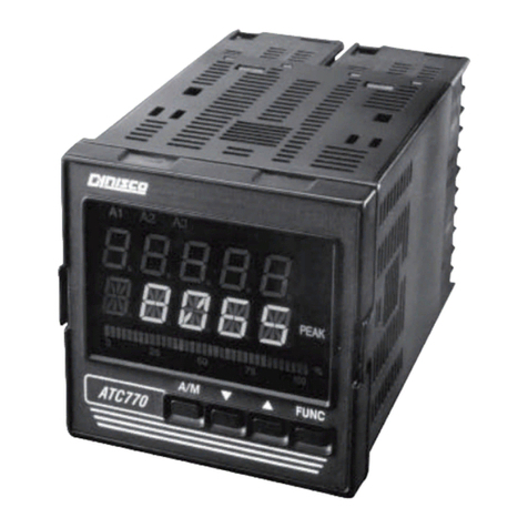
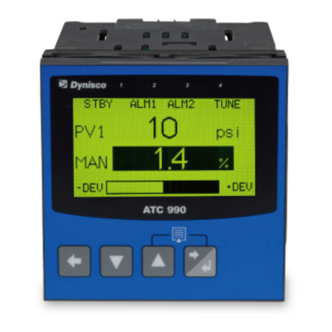
Dynisco ATC990 User manual

!
!
ATC$990$AND$UPR900$APPLICATIONS$AND$SETUP$
$
Rev:%10‐22‐2013%
Author:JDiOrio%
%
%
%
%
%
%
ATC990$Process$Controller$
and$
UPR900$Process$Indicator$
Technical$Notes,$Applications$and$Setup$
%

!
!
!"#$%&'()*+,--(.(/01,,-(2#34'56&3$'#(
)*+,--(2#5$&73'4(
!
Is!¼!Din!(96x96mm)!size,!117mm!depth!behind!the!panel.!It!has!1!or!2!inputs!for!the!indication/display!of!pressure,!
temperature!or!other!parameters.!
!
The!graphical!display!has!80!x!160!pixels,!and!a!red/green!colour!change!backlight.!
!
Flexible!output/option!combinations,!including!a!data!recorder!and!USB!port!
Input!types!include!Strain!gauge,!linear!mA/VDC,!thermocouples!or!RTDs!
(
/01,,-(1'#34'8894(
!
Features!and!options!are!as!on!the!UPR900,!but!with!the!addition!of!single!loop!PI/PID!control.!
ATC990!has!two!very!distinct!modes!of!operation:!Pressure!or!Temperature/standard!PID.!
Pressure!mode!has!options,!features,!tuning!and!calibration!tailored!to!the!specific!needs!of!the!Dynisco!core!business.!
Differential!pressure!control!possible!with!the!optional!2nd!input.!
!
The!Temperature/standard!PID!mode!offers!features!suitable!for!more!general!applications,!most!commonly!temperature:!
single!PID!(heat)!or!dual!PID!(e.g.!Heat!&!Cool),!but!also!%RH,!pH!etc.!

!
!
Strain'Gauge'Connection'&'Calibration'
)*+,--(.(/01,,-!
047#%56&94(:$4$#;(
(
For!6!wire!Dynisco!Transducers!and!test!box:(
!
2#<63(=(
094>$#78
%(
1'8'64(
?6#&3$'#(
2#<63(@(
094>$#78
%(
@(
+95(
A$;#78(B(
CD(
C(
E87&F(
A$;#78(G(
CH(
I(
:J$39(
KL&$373$'#(B(M=-N!1(BOG
PQR(
CP(
D(
S499#(
KL&$373$'#(G(
CT(
H(
E869(
178$U473$'#(+987"(M+G1/VR(
C,(
P(
W47#;9(
178$U473$'#(+987"(M+G1/VR(
I-(
(
A347$#(S76;9(2#<63(A933$#;%(
(
1. In!Input!Configuration,!select!Input!I!or!2,!then!choose!Strain!Gauge!as!the!Input!Type!(this!is!the!default!type).!
2. Choose!appropriate!Engineering!Units!such!as!KGcm,!Mpa!(Mega!Pascal),!psi!or!bar!(or#none).!
3. Select!number!of!decimal!places!to!display!(remember!the!display!has!a!maximum!of!5!digits!including!any!decimal!
places).!
4. Enter!a!value!for!Scale!Range!Upper!Limit!(this!would!equate!to!the!sensor!maximum),!and!the!Scale!Range!Lower!Limit!
(this!would!equate!to!the!sensor!minimum!–!typically!zero).!
5. There!is!a!filter!time!for!signal!noise.!
6. Select!Input!Failure!mode!as!High!or!Low!(makes!alarms!/!control!behave!as!thought!the!input!is!above!maximum!range!
or!below!minimum!range!if!the!signal!is!lost).!
7. Select!Peak!detection!to!Maximum,!Minimum!or!Disabled!(default).!This!adds!an!extra!Operator!Mode!screen!to!display!
either!the!highest!or!lowest!input!value!seen!since!it!was!last!reset.!Reset!performed!at!this!screen!by!pressing!UP!&!
DOWN!simultaneously.!It!can!also!be!reset!via!a!digital!input!if!fitted.!Four!digital!(logic)!inputs!are!now!standard!on!
UPR900,!and!optional!on!ATC990.(
!

!
!
A347$#(S76;9(A9>$G/63'>73$&(178$U473$'#(
!
If!enabled,!the!semi‐automatic!calibration!uses!a!resistor!present!within!the!pressure!transducer,!to!calibrate!the!instrument!
to!the!transducer.!The!resistor!is!used!to!force!the!mV!output!from!transducer!to!a!fixed!percentage!of!the!full!scale!value!
when!the!calibration!relay!shorts!out!the!R‐CAL!connections.!Strain!Gauge!Calibration!is!a!sub‐menu!option!in!Input!
Configuration,!but!can!also!be!accessed!at!any!time!by!pressing!DOWN!and!FORWARD!simultaneously.!Allow!time!for!the!
instrument!and!process!to!reach!operating!temperature!before!starting.!The!first!strain!gauge!input!is!calibrated!then!the!
second!if!it!is!fitted!and!configured.!
1. Select!the!Shunt!Resistor!as!K#7U895.!If#enabled#the#semi‐automatic#calibration#procedure#is#used.#If#it#is#disabled,#use#
the#Manual#calibration#instructions#below.!
2. Set!the!Calibration!Resistor!value!(default!=!80%!of!sensor!maximum).!The#instrument#must#know#what#percentage#will#
be#applied#to#calibrate#correctly#–#Check#sensor#datasheet.!
3. At!the!Low!Point!Calibration!screen,!ensure!the!transducer!is!at!working!temperature!with!zero!pressure!applied,!then!
press!UP!and!DOWN!simultaneously.!Low#end#calibration#is#performed#and#a#completed#message#shown.#The#error#
message#“Count#Failure”#is#shown#if#the#input#was#not#±10mV#of#the#nominal#0mV#expected#signal,#and#calibration#is#not#
altered.#0J$%(&'685(%$;#$X"(7(X7683"(347#%56&94Y(Z'6(&7#('#8"(>'[9('#3'(J$;J(9#5(&78$U473$'#('#&9(3J9(<4'U89>($%(
&'449&395(7#5(8'\(&78$U473$'#(J7%(U99#(&'><89395(%6&&9%%X688"]!
4. At!the!High!Point!Calibration!screen,!press!UP!and!DOWN!simultaneously.!The!calibration!relay!turns!ON!to!short!the!R‐
CAL!terminals!together!and!force!required!%mV!value!to!be!output!from!transducer!into!the!instruments!input.!High#
end#calibration#is#performed#and#a#completed#message#shown.#The#error#message#“R#Cal#Failure”#is#shown#if#the#signal#
was#less!than!+20mV!or!greater!than!+50mV,#and#calibration#is#not#altered.#0J$%(&'685(%$;#$X"(7(X7683"(347#%56&94(+G178(
49%$%3'4Y(+9<973(3J9(&78$U473$'#(<4'&95649('#&9(3J9(<4'U89>($%(&'449&395Y!
5. The!procedure!from!1!to!4!is!repeated!if!a!2nd!strain!gauge!input!is!configured.!
!
!
A347$#(S76;9(^7#678(178$U473$'#(
!
If!the!shunt!is!disabled,!a!Manual!Calibration!needs!to!be!performed!by!user.!Manual!Calibration!requires!the!user!to!input!
known!Zero!Offset!and!Full!Scale!mV!values!into!the!input!terminals!of!the!instrument!using!an!accurate!mV!calibration!
source.!
!
The!Manual!Calibration!process!for!the!low!offset!is!as!follows:!!
1. Ensure!Unit!is!powered!on!and!mV!Input!from!the!calibration!signal!source!is!wired!to!the!instrument’s!strain!gauge!
input!terminals.!
2. Enter!the!Strain!Gauge!Calibration!mode,!(e.g.!press!DOWN!and!FORWARD!simultaneously).!
3. Select!the!Shunt!Resistor!as!Disabled.!
4. The!Calibration!Resistor!percentage!value!is!fixed!to!100.0%!and!cannot!be!changed!by!the!user.!
5. At!the!Low!Point!Calibration!screen,!check!that!the!calibration!signal!is!set!to!exactly!the!transducer!mV!signal!at!zero!
pressure,!then!press!UP!and!DOWN!simultaneously.!Low#end#calibration#is#performed#and#a#completed#message#shown.#
The#error#message#“Count#Failure”#is#shown#if#the#input#was#not#±10mV#of#the#nominal#0mV#expected#signal,#and#
calibration#is#not#altered.#1J9&F("'64(%$;#78(7#5(49<973(3J9(&78$U473$'#(<4'&9%%(X4'>(3J9(%3743Y(Z'6(&7#('#8"(>'[9('#3'(
J$;J(9#5(&78$U473$'#('#&9(8'\(&78$U473$'#(J7%(U99#(&'><89395(%6&&9%%X688"]!
6. At!the!High!Point!Calibration!screen,!check!that!the!calibration!signal!is!set!to!the!full!scale!mV!signal!as!per!the!
transducer!datasheets!(e.g.!33.3mV),!then!press!UP!and!DOWN!simultaneously.!High#end#calibration#is#performed#and#a#
completed#message#shown.#The#error#message#“R#Cal#Failure”#is#shown#and#calibration#is#not#altered#if#the#signal#was#
less!than!+20mV!or!greater!than!+50mV!OR!the!High!Cal!–!Low!Cal!value!is!less!than!10mV.#1J9&F("'64(%$;#78(7#5(
49<973(3J9(&78$U473$'#(<4'&9%%(X4'>(3J9(%3743Y!

!
!
!
178$U473$'#(+9>$#594!
!
A!calibration!reminder!can!be!set!if!Data!Recorder!option!is!fitted!(which!means!instrument!has!battery‐backed!Real!Time!
Clock).!The!addition!of!a!clock!means!that!the!instrument!can!be!aware!of!the!date!and!time!(even!when!powered!down).!
This!information!can!be!used!to!remind!the!user!to!calibrate!the!inputs!at!a!specified!future!date.!The!date!is!set!in!the!Input!
Configuration!menu.!If!enabled!and!the!date!set!is!exceeded,!a!calibration!due!screen!is!shown!every!24hrs!(and!at!every!
power‐up)!until!it!is!changed!to!a!future!date!(or!disabled).!
!
V$#974(7#5(09><9473649(178$U473$'#(.(A&78$#;(
)*+,--(.(/01,,-!
V$#974(M#'#G%347$#(;76;9R(7#5(09><9473649(178$U473$'#(
(
The!instrument!offers!single!point!calibration,!with!zero!offset!adjustment!only,!or!two!point!calibration,!with!both!zero!&!
span!adjustments.!
!
A$#;89(*'$#3(178$U473$'#(
!
A!‘zero!offset’!applied!to!the!process!variable!across!the!entire!span.!Positive!values!are!added!to!the!reading,!negative!
values!are!subtracted.!Can!be!used!if!the!error!is!constant!across!the!range,!or!the!user!is!only!interested!in!a!single!critical!
value.!
To!use,!select!Single!Point!Calibration!from!the!input!calibration!menu,!and!enter!a!value!equal,!but!opposite!to!the!observed!
error!to!correct!the!reading.!
!
!
!
This!example!shows!a!positive!offset!value.!
For!example:!
If!the!process!displays!27.8!when!it!should!
read!30,!The!error!is!‐2.2!so!an!applied!
offset!of!+2.2!would!change!the!displayed!
value!to!30.!
The!same!offset!is!applied!to!all!values,!so!
at!100.0!the!new!displayed!value!would!be!
102.2.!
!
(
0\'(*'$#3(178$U473$'#(
!
This!method!is!used!where!an!error!is!not!constant!across!the!range.!
Separate!offsets!are!applied!at!two!points!in!the!range!to!eliminate!both!“zero”!and!“span”!errors.!To!use:!
1. Measure!and!record!the!error!at!a!low!point!in!the!process.!
2. Measure!and!record!the!error!at!a!high!point!in!the!process.!
3. Go!to!the!first!two!point!input!calibration!screen.!
a. Enter!the!desired!low!point!value!as!the!Calibration!Low!PV!value.!
Single!Point!‘Offset!
Calibration’!value!
!
New!Displayed!Value!
Original!Displayed!
Value!

!
!
b. Enter!an!equal,!but!opposite!value!to!the!observed!error!as!the!Calibration!Low!Offset!to!correct!the!error!at!the!low!
point.!
4. Go!to!the!second!two!point!input!calibration!screen.!
a. Enter!the!desired!high!point!as!the!Calibration!High!PV!value.!
b. Enter!an!equal,!but!opposite!value!to!the!observed!error!as!the!Calibration!High!Offset!to!correct!the!error!at!the!high!
point.!
!
!
!
This!example!shows!a!positive!Low!Offset!
and!a!negative!High!Offset.!For!example:!
If!the!process!displays!+0.5!at!the!low!end,!
an!offset!of!‐0.5!would!change!the!value!to!
0.0!
A!high!end!value!of!98.3!with!a!+1.7!offset!
would!read!100.0.!
There!is!a!linear!relationship!between!
these!two!calibration!points.!
!
((
1/)02W_`(1J''%9([7869%(7%(#974(7%(<'%%$U89(3'(3J9(U'33'>(7#5(3'<('X("'64(6%7U89(%<7#(3'(
7&J$9[9(>7L$>6>(&78$U473$'#(7&&647&"Y(0J9(9XX9&3('X(7#"(944'4(&7#(;4'\(<7%3(3J9(&J'%9#(
&78$U473$'#(<'$#3%Y(
!
^683$G<'$#3(A&78$#;!
!
If!an!input!is!connected!to!a!linear!input!signal!(mA,!mV!or!VDC),!multi‐point!scaling!can!be!enabled!for!that!input!to!allow!
linearization!of!a!non‐linear!signal.!–!see!Input!Configuration!Sub‐Menu.!
The!Scale!Input!Upper!&!Lower!Limits!define!the!values!shown!when!the!input!is!at!its!minimum!and!maximum!values.!Up!to!
15!breakpoints!can!scale!the!input!vs.!displayed!value!between!these!limits.!It!is!advisable!to!concentrate!the!break!points!in!
the!area!of!the!range!with!the!most!non‐linearity,!or!an!area!of!particular!importance!to!the!application.!
!
To!use,!set!the!scale!limits,!and!then!enter!the!1st!scaling!point!(this!is!a!%!of!the!scaled!input!span,!and!the!desired!display!
value!to!be!shown!at!that!input!value.!Next!set!the!2nd!point!and!display!value,!followed!by!the!3rd!etc.!Continue!unit!all!
breakpoints!are!used!or!you!have!reached!100%!of!the!input!span.!A!breakpoint!set!at!100%!ends!the!sequence!
!
178$U473$'#(+9>$#594!
!
A!calibration!reminder!can!be!set!if!Data!Recorder!option!is!fitted!(which!means!instrument!has!battery‐backed!Real!Time!
Clock).!The!addition!of!a!clock!means!that!the!instrument!can!be!aware!of!the!date!and!time!(even!when!powered!down).!
This!information!can!be!used!to!remind!the!user!to!calibrate!the!inputs!at!a!specified!future!date.!The!date!is!set!in!the!Input!
Configuration!menu.!If!enabled!and!the!date!set!is!exceeded,!a!calibration!due!screen!is!shown!every!24hrs!(and!at!every!
power‐up)!until!it!is!changed!to!a!future!date!(or!disabled).!
Original!Displayed!Value!
!
New!Displayed!Value!
Calibration!High!Offset!
Calibration!Low!Offset!
Calibration!Low!
Process!Value!
Calibration!Low!
Process!Value!

!
!
A933$#;()<(/01,,-(X'4()%9(
*49%%649(A936<(.(/63'>73$&(06#$#;(.(W<9473$'#(
(
1. Power!up!the!instrument!and!if!in!automatic!control!mode(1.),!change!to!manual!mode!at!0%!power/0!RPM(2)..!Set!the!
alarm!types!and!values!as!required!for!your!application!(see!alarm!configuration).!
2. Set!local!setpoint!1!as!the!active!setpoint,!and!its!value!to!the!required!operating!pressure(3).!
3. Allow!the!process!to!reach!operating!temperature,!then!carefully!adjust!the!manual!power!level!(use!UP!&!DOWN!keys!
from!the!main!screen)!to!bring!the!process!approximately!to!the!operating!pressure.!
4. Select!the!automatic!tuning!menu,!and!set!“Run!Pressure!Pre‐Tune”!to!YES.!
5. Press!the!RIGHT!key.!The!Pressure!Tune!Status!screen!shows!the!current!status!‐e.g.!“Running”,!and!The!TUNE!LED!is!
flashes!until!the!pre‐tune!is!completed.!
6. The!instrument!adds!the!defined!Pressure!Tune!Output!pulse(4.)!to!the!current!manual!power!level,!the!process!reaction!
is!observed!and!the!instrument!calculates!and!stores!the!correct!PI!tuning!terms.!Pre‐tune!is!now!complete!and!exits.!
7. Automatic!control!can!now!be!selected,!where!the!control!power!output!level!is!maintained!by!the!controller.!If!
setpoint!mode!was!selected!as!the!auto/manual!transfer!method,!some!adjustment!of!the!setpoint!may!be!required(5.).!
8. Optionally!Pressure!Self‐Tune!may!be!used!once!in!automatic!control!mode,!by!selecting!the!automatic!tuning!menu,!
and!setting!“Run!Pressure!Self‐Tune”!to!YES(6.).!The!TUNE!LED!is!lit!if!Self‐tune!is!enabled.!
!
_'39%(X'4(A936<(.(/63'>73$&(06#$#;(.(W<9473$'#(
(
1. The!initial!“power‐up!control!state”!can!be!set!to!manual!or!automatic!from!the!control!configuration!menu,!the!default!
is!manual!mode!at!0%!power(2)..!Auto!or!manual!mode!can!be!selected!from!the!auto/manual!control!menu,!or!to!
immediately!go!to!manual!mode!from!any!point,!simply!press!the!LEFT!&!RIGHT!keys!simultaneously.!
The!transition!from!auto!to!manual!control!while!running!is!Bumpless.!It!takes!the!last!PI!power!level!as!the!initial!
manual!control!power!level.!
!
2. Manual!power!can!be!expressed!in!%!or!RPM.!For!RPM,!enable!“Scaled!Power”!in!the!control!configuration!menu,!then!
scale!0%!and!100%!power!to!their!equivalent!RPM!values).!
!
!
3. Setpoint!Select!and!the!setpoint!value!screen!is!in!operation!mode.!Setpoint!upper!and!lower!limits!can!be!set!in!the!
control!configuration!menu.!
!
4. The!Pressure!Tune!Output!pulse!value!is!set!in!the!control!configuration!menu.!The!pulse!can!be!from!‐25%!to!+25%.!
Default!is!10%.!
!
!
5. The!method!of!transition!from!manual!to!automatic!control!is!set!in!the!control!configuration!menu.!Two!methods!are!
possible,!both!ensure!a!smooth!transition!to!automatic!mode:!
a. Bumpless!Mode!sets!the!initial!PI!power!level!to!match!the!previous!manual!power!vale,!then!uses!the!integral!
function!progressively!alter!the!power!to!the!correct!value.!
b. Setpoint!Mode!modified!the!current!Setpoint!value!to!the!measured!input!pressure!value!at!the!time!of!switchover.!
The!operator!can!change!the!setpoint!value!from!the!setpoint!value!screen!and!the!PI!control!algorithm!will!adjust!
the!process!to!this!value.!

!
!
6. The!self‐tune!is!a!continuous,!on!on‐line!algorithm!that!"observes"!the!measured!value!and!looks!for!oscillation!due!to!
load!variations!or!set‐point!changes.!When!a!significant!pattern!is!recognized!the!tuning!parameters!are!automatically!
adjusted.!
When!Self‐tune!is!running!the!PI!parameters!(PB,!TI)!are!read!only!in!the!operator!menus.!
!
The!type!of!automatic!tuning!available!depends!on!which!mode!the!controller!is!in!(Pressure!or!Non‐Pressure),!and!whether!
the!control!is!manual!or!automatic.!
!
!
!

!
!
/874>%(.(V73&J$#;(W63<63%(
)*+,--(
/874>%(
(
In!Alarm!Configuration,!there!are!up!to!3!alarms!selectable!as!Process!High,!Process!Low,!Rate!of!Signal!Change!
(per!minute),!Sensor/input!Break,!!
The!alarm!source!can!be!input!1!or!2!
!
Enter!the!value!(threshold)!at!which!the!alarm!should!occur,!an!adjustable!hysteresis!value!and!an!alarm!filter!time!
(this!is!the!minimum!duration!for!on!to!happen,!but!if!set!to!OFF!activation!is!immediate).!There!is!also!an!option!to!
inhibit!(mask)!an!alarm!at!power‐up.!
!
Colour!change!on!alarm!is!optional!(set!in!Display!Configuration)!
!
W63<63%(
(
Only!relays!can!be!used!as!alarm!outputs.!In!Output!Configuration,!select!a!relay!output!to!use,!then!select!Alarm!
1,!2!or!3!(direct!or!reverse!acting).!Alternatively,!select!Boolean!logical!output!of!alarms!1!W+!2,!or!alarms!1,!2!W+!3!
(these!also!can!be!direct!or!reverse!acting).!Reverse!action!with!OR!would!equate!to!Boolean!_W+.!
Each!output!can!be!selected!to!latch!or!not!independently.!
!
)%7;9(
(
If!the!alarm!threshold!is!exceeded!for!longer!than!the!filer!time!(assuming!no!power‐up!inhibit),!the!alarm!
activates,!and!relay!changes!state.!
!
NOTE:!from!normal!main!operator!screen,!pressing!the!BACK!key!shows!the!Alarm!Status!Screen,!and!another!
press!will!show!the!Clear!Latched!Outputs!screen!(if!any!are!latched).!
!
When!alarm!threshold!is!no‐longer!exceeded,!the!alarm!turns!off!and!a!non‐latching!relay!output!would!also!
change!back.!However,!if!the!relay!output!was!set!for!latching!it!would!not!change!back.!
At!the!Clear!Latched!Outputs!screen,!use!FORWARD!or!BACK!keys!to!select!the!latched!outputs,!then!press!the!UP!
or!DOWN!key!to!unlatch!it.!NOTE:!The!output!can!only!be!unlatched!if!the!associated!alarm!is!no‐longer!active.!
!
/01,,-(
(
As!UPR900!except!additional!alarm!types!are!possible:!
PV‐SP!Deviation,!Band,!Control!Loop,!Percentage!memory!used,!High!and!Low!power.!

!
!
!$;$378(MV';$&R(2#<63Y(
)*+,--(
!$;$378(2#<63(A<9&$X$&73$'#%(
(
The!four!digital!inputs!operate!from!either!a!DC!voltage!signal!or!switch!closure!(“volt!free”!contacts)!
Open!contacts!(>5000!ohm)!or!2!to!24VDC!signal!=!Logic!High!
Closed!contacts!(<50!ohm)!or!‐0.6!to!+0.8VDC!signal!=!Logic!Low.!
Five!rear!terminals!are!used.!25!to!28!are!C1!to!C4!+ve!input,!with!33!a!shared!common!–ve!
They!are!“Edge!Sensitive”!requiring!a!high!to!low!or!Low!to!High!logic!state!transition!to!change!the!function!status.!Current!
state!is!remembered!at!power!down.!
!
!
!$;$378(2#<63(1'#X$;6473$'#(
(
The!four!digital!(or!logic)!inputs!are!setup!in!a!sub‐menu!of!Input!Configuration!called!“Digin!Function!Select”.!They!are!
numbered!C1!to!C4.!
!
Each!of!these!can!be!set!perform!a!single!function!from!this!list:!
•!IP1!Peak!Reset! ! ! Resets!stored!peak!value!to!match!the!current!input!1!value.!
•IP2!Peak!Reset! ! ! Resets!stored!peak!value!to!match!the!current!input!2!value.!
•IP1/2!Peak!Reset! ! Resets!stored!peaks!to!match!the!current!input!1!&!2!values.!
•Alarm!Reset! ! ! Resets!any!latched!alarm!output!relays!(if!alarm!not!active).!
•IP1!Peak!&!Alarm!Reset! ! Resets!latched!alarms!and!input!1!stored!peak!value!
•IP2!Peak!&!Alarm!Reset! ! Resets!latched!alarms!and!input!2!stored!peak!value!
•IP1/2!Peak!&!Alarm!Reset! Resets!latched!alarms!and!input!1!stored!peak!value!
•IP1!Zero!Calibration! ! Performs!a!zero!calibration!on!input!1!
•IP2!Zero!Calibration! ! Performs!a!zero!calibration!on!input!2!
•IP1/2!Zero!Calibration! ! Performs!a!zero!calibration!on!input!1!and!2!
•IP1!Zero!Cal,!Alrm,!Pk!Reset! Performs!IP1!zero!cal,!plus!resets!peak!&!latched!outputs!
•IP2!Zero!Cal,!Alrm,!Pk!Reset! Performs!IP2!zero!cal,!plus!resets!peak!&!latched!outputs!
•IP1/2!Zero!Cal,!Alrm,!Pk!R! Performs!IP1&2!zero!cal,!plus!resets!peak!&!latched!outputs!
•Data!Recorder! ! ! Starts/pauses!the!recording!of!data!(if!recorder!fitted)!
/01,,-(
(
As!UPR900!except,!these!additional!Digital!Input!functions:!
•Setpoint!Selection! ! Selects!between!the!local!and!alternate!setpoints!
•Auto/Manual!Ctrl!Select!! Switches!the!control!between!automatic!and!manual!modes!
•PID!Control!Outputs! ! Enables!or!Disables!the!PID!controller!outputs!
•Run!Pre!Tune! ! ! Engages!the!controllers!automatic!Pre‐Tune!function!
•Run!Self!Tune! ! ! Engages!the!controllers!automatic!Self‐Tune!function!
•Increment!Control!Output! Increases!the!control!output!value!(0‐100%!in!20s)!
•Decrement!Control!Output! Reduces!the!control!output!value!(100‐0%!in!20s)!

!
!
/63'>73$&(%37#5GU"(
/01,,-(
/63'>73$&(%37#5GU"(?973649(
(
The!automatic!stand‐by!function!avoids!overshoots!following!temporary!process!interruptions!(i.e.!if!the!pressure!goes!to!
zero)!that!may!cause!the!controllers!integral!component!to!saturate.!When!the!process!restarts,!a!saturated!output!is!likely!to!
cause!an!excessive!and!potentially!dangerous!overshoot!(starting!the!motor!at!full!speed).!This!feature!is!not!active!while!in!
manual!control!mode.!
!
The!parameters!are:!
1. Pressure!Stand‐by!Threshold!
Automatic!stand‐by!pressure!threshold!value!to!switch!controller!into!the!automatic!stand‐by!sequence!(in!physical!
units!from!0!to!15!%!of!full!scale!or!OFF).!Input!excursions!of![SP±!Threshold]!start!the!automatic!stand‐by!feature.!
If!set!to!OFF,!the!automatic!stand‐by!feature!is!disabled.!
2. Pressure!Stand‐by!Recovery!Time!
The!maximum!of!time!(from!1!to!60!seconds)!the!automatic!stand‐by!sequence!is!allowed!to!continue.!If!the!excursion!
lasts!longer!than!this!time,!manual!mode!with!0%!controller!output!is!applied!(emergency!stop).!
3. Pressure!Stand‐by!Active!Limit!
An!active!power!limitation!value.!It!limits!power!to!the!“known!good!steady!state!power”!required!±!the!Pressure!Stand‐
by!Active!Limit!value.!This!improves!safety!for!a!very!sensitive!reacting!pressure!processes!by!avoiding!large!deflections.!
(
)%$#;(/63'>73$&(%37#5GU"(
(!
The!automatic!stand‐by!function!is!activated!by!setting!the!Pressure!Stand‐by!Threshold!to!a!value!other!than!OFF.!The!
unfiltered!controller!input!is!monitored!(not#the#slower#filtered#display#value),!and!when!it!leaves!the!band!above!or!below!
the!setpoint!set!by!the!“Pressure!Stand‐by!Threshold”!parameter,!the!output!is!immediately!set!to!the!steady!state!value!
stored!when!the!process!was!first!stable(1.!see!Finding!the!Steady!State!Power!below).!
!
If!the!input!recovers!within!the!“Pressure!stand‐by!recovery!time”,!the!controller!waits!for!two!and!half!time!the!integral!
value!(2.5!*!Ti)!and!then!returns!to!normal!“running”!conditions.!
!
If!the!process!input!does!not!recover,!the!output!remains!at!the!steady!state!value!until!the!Pressure!stand‐by!recovery!time!
has!elapsed,!at!which!time!the!controller!is!switched!to!manual!mode!at!0%!power.!
!
_'39`($X(3J9(*49%%649(%37#5GU"(49&'[94"(3$>9($%(%93(3'(W??a(3J9(&'#34'8894(9#394%(>7#678(>'59(73(3J9(%3'495(%3975"(%3739(
[7869a($>>95$7398"(3J9(*49%%649(A37#5GU"(0J49%J'85($%(9L&99595Y(
Changing!the!setpoint!while!the!Automatic!stand‐by!is!active!will!cancel!the!stand‐by!sequence.!It!will!not!be!able!to!activate!
until!a!new!steady!state!value!has!been!found.!
!
**The!old!model!ATC880!monitor!the!input!and!output!the!feature!only!began!if!the!threshold!was!passed!and!the!output!
was!at!saturation.!ATC990!monitors!the!input!level,!but!not!output!saturation!because!the!process!could!see!heavy!
disturbances!before!the!output!is!saturated.!
!

!
!
/63'>73$&(%37#5GU"(KL7><89(
!
For!example,!in!a!process!with!these!conditions!set:!Setpoint=6000;!Pressure!Stand‐by!Threshold!=200!Stand‐by!Recovery!
Time=30seconds;!Stand‐by!Active!Limit=20.0!and!Integral!Time(Ti)=10seconds!
1. Stand‐by!begins!immediately!at!SP+Threshold!(6200)!or!SP‐Threshold!(5800).!
2. If!normal!input!returns!(within!band!of!5801!to!6199)!in!less!that!the!recovery!time,!normal!power!resumes!after!2.5x!
the!integral!time!(25s).!
3. If!normal!input!does!not!resume!in!in!less!that!the!recovery!time,!0%!manual!mode!power!is!applied.!The!user!must!
return!the!controller!to!automatic!mode!and!allow!a!new!steady!state!power!to!be!stored!before!the!feature!can!
become!active!again.!
4. If!the!recovery!time=OFF,!manual!mode!is!instantly!applied,!with!power!set!to!the!steady!state!value.!
?$#5$#;(3J9(A3975"(A3739(*'\94.Y!
For!a!stable!(steady!state)!condition,!the!process!value!must!be!inside!the!requested!band![Setpoint!±Pressure!Stand‐by!
Threshold]!for!more!than!one!minute.!The!power!level!needed!to!achieve!the!stable!condition!is!called!the!steady!state!value.!
See#figure#1a#below.#
Once!calculated!the!stored!value!remains!unchanged!until!there!is!a!change!of!the!setpoint,!or!the!controller!is!changed!from!
automatic!to!manual!mode.!If!this!happens,!a!new!steady!state!value!must!be!found,!and!the!automatic!stand‐by!feature!
cannot!function!until!it!has!been!stored.!!
!
?$#5$#;(A3975"(A3739(*'\94!
/&3$[9(*'\94(V$>$3$#;(
(
!
?$;649(=7(
?$;649(=U!
!
)%$#;(A37#5GU"(/&3$[9(V$>$3Y(
(
In!addition!to!the!automatic!stand‐by!feature!itself,!further!protection!to!the!process!is!given!by!the!Stand‐by!Active!Limit.!Its!
purpose!is!to!limit!the!output!swing!possible!in!very!sensitive!reacting!pressure!process.!This!works!by!limiting!the!power!
applied!to!the!process!to!not!more/less!than!the!stored!steady!state!value!±!the!Stand‐by!Active!Limit!set!by!the!user.!See#
figure#1b#above.#
!
If!the!stored!steady!state!value=50%!and!stand‐by!active!limit=20%,!the!overall!limits!would!be!30%!to!70%.!
!

!
!
Setting!a!Stand‐by!Active!Limit!value!of!100%!would!effectively!disable!this!function.!
_'39`(2X(3J9(A3975"(A3739(*'\94(89[98(J7%(#'3(U99#(X'6#5(M'4($%(49%93(U9&76%9('X(7(%93<'$#3(&J7#;9('4(%\$3&J(3'(>7#678(
>'59R(3J9(<'\94(8$>$3%(749(-Q(7#5(=--Q(6#3$8(3J9(#9\([7869($%(%3'495Y(
(
Other manuals for ATC990
1
This manual suits for next models
1
Table of contents
Other Dynisco Controllers manuals