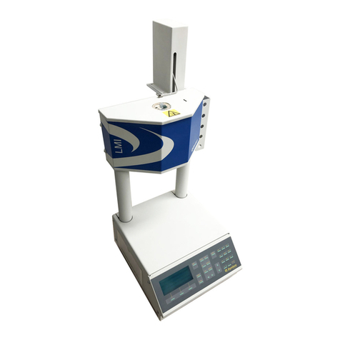
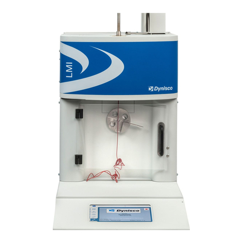
Dynisco LCR7000 Series User manual

LCR7000 & RHEOSIGHTS P/N: 974194 | Rev: A| ECO: 52468
www.dynisco.com
From lab to production,
providing a window into the process
-1-
Setting the standard for Evaluating Polymer
Melt Flow Characteristics
Operating Manual
Dynisco
LCR7000
Series
& RheoSights

LCR7000 & RHEOSIGHTS P/N: 974194 | Rev: A| ECO: 52468
www.dynisco.com
From lab to production,
providing a window into the process
-2-
Contents
Introduction ............................................................................................................................................................5
Getting Started .......................................................................................................................................................7
Safety ...................................................................................................................................................................... 14
Test Drive.............................................................................................................................................................. 20
RheoSights Operations..................................................................................................................................... 23
Set Up Test Page ................................................................................................................................................. 25
HAMA Laser Micrometer................................................................................................................................. 33
Rheometer Control Screen ............................................................................................................................. 35
Plotting and Analyzing your Data................................................................................................................ 37
Built-in Functionalities of the Graphing Tool................................................................................ 38
RheoSights Reports........................................................................................................................................... 47
Formulas Used in Data Analysis................................................................................................................... 54
Apparent Shear Rate Calculation: ...................................................................................................... 54
Apparent Shear Stress Calculation: ................................................................................................... 54
Apparent Shear Viscosity ...................................................................................................................... 55
Volumetric Flow Rate Calculation: .................................................................................................... 55
Mass Flow Rate Calculation:................................................................................................................. 56
Introduction to Rheology................................................................................................................................ 57
Simple Shear Deformation.................................................................................................................... 57
Viscosities of some Common Materials ............................................................................................... 62
......................................................................................................................................................................... 62
Pseudoplastic ............................................................................................................................................. 63
Dilatant......................................................................................................................................................... 63
Thixotropic.................................................................................................................................................. 63
Rheopectic................................................................................................................................................... 63
Where: ηis viscosity, τis the shear stress and γis the shear rate.................................................. 64
Advantages of a pressure transducer................................................................................................... 67
Disadvantages of a pressure transducer ............................................................................................ 67
Maintenance and Calibration ........................................................................................................................ 71
Galaxy ..................................................................................................................................................................... 87

LCR7000 & RHEOSIGHTS P/N: 974194 | Rev: A| ECO: 52468
www.dynisco.com
From lab to production,
providing a window into the process
-3-
Extras...................................................................................................................................................................... 89
Measurement of Melt Density.............................................................................................................. 89
The Non-Newtonian Index.................................................................................................................... 89
Troubleshooting ................................................................................................................................................. 91
Parts List................................................................................................................................................................ 94
DIES and ORFICES.................................................................................................................................... 94
Die Design and Configuration.............................................................................................................. 97
Supplied Hand Tools......................................................................................................................................... 98
LCR 7000 SPARE PARTS LIST ................................................................................................................100
Navigating the Keypad...................................................................................................................................103
The Keypad ...............................................................................................................................................103
Keypad Definitions.................................................................................................................................103
Conversion Factors..........................................................................................................................................105
Example Runs....................................................................................................................................................106
Support Vendors ..............................................................................................................................................110
RAM Rate / Shear Rate Table ......................................................................................................................112
Reference Books...............................................................................................................................................113
Glossary of Terms …………………………………………………………………………………………………..115

LCR7000 & RHEOSIGHTS P/N: 974194 | Rev: A| ECO: 52468
www.dynisco.com
From lab to production,
providing a window into the process
-4-

LCR7000 & RHEOSIGHTS P/N: 974194 | Rev: A| ECO: 52468
www.dynisco.com
From lab to production,
providing a window into the process
-5-
Introduction
This manual describes the setup procedure and basic operation of the DYNISCO POLYMER
TESTS 7000 series capillary rheometers. It provides the complete description of resources
at your command when operating your rheometer. It is not necessary to read this manual
in its entirety; however, even experienced rheologists and technicians can benefit from the
safety tips and cleaning suggestions learned over many years of operating these
rheometers at our in-house polymer testing labs.
The Getting Started Chapter explains the details of setting up the instrument, important
safety issues, and walks the user through two standard tests. Experienced users may wish
to skip over the initial runs if familiar with entering programs into the rheometer.
Italics: Rheological items which, have defining equations presented in this manual, are
shown in italics.
Bold Italics: These are parameters that are set from the front panel on the rheometer (i.e.
Melt Time, Delay Time etc.). These parameters are entered into the rheometer's control
programs via the rheometer keypad.
BOLD ALL CAPITALS: This indicates an actual key found on the rheometer keypad. Usage
is as follows: Press the ESC button to stop the rheometer movement.
Underlined Items: Underlined items head paragraphs or sections that pertain to the
particular item or model underlined. If you do not have or are not interested in the
underlined item skip the section that follows it. Underlining is also used to emphasize
safety issues.
This manual was produced using WORDfor Windows. Figures from DYNISCO POLYMER
TEST's Advanced Rheology Software (RheoSights)were imported directly from plot files
made using ALT-F3 from the RheoSightsgraphics screen. Figures can also be imported
into WordPerfectusing the Graphics Retrieve command.
1. How to use this manual
2. Typographic Conventions

LCR7000 & RHEOSIGHTS P/N: 974194 | Rev: A| ECO: 52468
www.dynisco.com
From lab to production,
providing a window into the process
-6-
Call Dynisco at +1-508-541-9400 or contact your local sales representative for the latest pricing information. Orders
can also be placed online at https://shop.dynisco.com or https://shopeu.dynisco.com.Account registration is
required
To help us handle your questions as quickly as possible, have the following items ready before you call:
•Rheometer name and model number
•Rheometer serial number (on back panel of the unit)
•Computer/system make and model
•Current version of software (Found at the bottom on the main operating page of the RheoSights software)
DYNISCO, Customer Service
38 Forge Parkway
Franklin, MA 02038-3134
United States
3. How to Contact DYNISCO

LCR7000 & RHEOSIGHTS P/N: 974194 | Rev: A| ECO: 52468
www.dynisco.com
From lab to production,
providing a window into the process
-7-
Getting Started
The instrument arrives in a crate weighing approximately 770 kg (350 lb.) measuring 165
X 63.5 X 61 cm (65” X 25” X 24”). Save the crate until you are fully satisfied with the
operation of your instrument. We recommend that you save the shipping crate for future
shipments of the rheometer back to Dynisco for upgrades, service and/or calibration, or for
your own facility or rheometer relocation.
Remove the lid to the crate, labeled TOP, by removing the wood screw fasteners. Remove
only the shipping restraints for the boxes shipped inside the crate and then remove the
boxes. Stand the crate up, with the instrument still inside, so that the instrument is right
side up. Remove all instrument-shipping restraints taking care that the instrument
does not shift and fall out of the crate. Walk the instrument out of the box, “Caution,
there may be a shipping restraint under the instruments feet”. Once fully removed, check
for any shipping damage and contact the factory if necessary.
Typical laboratory benches are too high for efficient use of the rheometer. Cleaning can be
difficult and requires awkward hand positions and forces, which could lead to carpal tunnel
syndrome or back discomfort. We strongly suggest a bench height of 29 inches (desktop
height) for an average height operator. Place the front of the rheometer flush with the edge
of the table. This will prevent the operator from having to bend forward excessively when
cleaning the barrel and allow easier access to the back of the rheometer. As a minimum,
the lab bench should easily be able to support the rheometer and operator (approximately
500 lbs.). The bench top should also be able to withstand hot dies and tools being dropped
on them. Carpet protection is necessary near the rheometer since a hot die dropped on the
carpet will quickly burn the carpet.
Adequate ventilation will also be required to remove potentially harmful fumes from
samples being tested. Consult the Material Safety Data Sheets (MSDS) on the products to
be tested, and check with your material supplier to assess the magnitude of your
ventilation needs. You may wish to consider these ventilation needs when positioning the
instrument in the laboratory.
1. Uncrating and Setup
2. Bench Requirements and Placement

LCR7000 & RHEOSIGHTS P/N: 974194 | Rev: A| ECO: 52468
www.dynisco.com
From lab to production,
providing a window into the process
-8-
Most of the rheometer comes pre-assembled to your door, however certain parts are prone
to breakage if they were placed in their normal operating position during shipping. These
items will need to be installed before safe operation of the rheometer is possible. These
items include the Load Cell (models 7000 & 7001), Interface cables for the Load Cell and
Pressure Transducers (models 7001 & 7002), Cable connection for the Edge Device, printer
(if applicable), Laser Micrometer (if applicable), and AC Power connections.
Keep the wooden crate in storage in case you ever need to move or ship the rheometer
back to Dynisco or to another location.
First find the surge protector/power box. This is an extension cord with many sockets
available for use. Plug it in and make sure the power is OFF (the ON switch should not be
lit). There are a number of power cords supplied with the rheometer. The thickest
(heaviest) of these is used for the rheometer. Connect this thickest cord to the back of the
rheometer base and into the isolated filter bank #3 in the power box. Power to the PC and
monitor should connect to the isolated filter bank #1. The printer (if used) can be
connected to any remaining outlet.
The data processing system consists of an Edge Device and the RheoSights software
package. Connecting the interface cable, from the back of the rheometer, to any USB port on
the Edge Device, makes the link between the Edge Device and the rheometer. On the back
panel of the rheometer, you will find a female DB9 connector for a serial port connection.
If you have purchased the HAMA Laboratories PA02L High Resolution Laser Micrometer
(available for models 7000, 7001, and 7002), you will find a digital I/O board, and interface
cable, and the laser micrometer itself. The digital I/O board base address switch is preset
at 2E0h. If this address is already assigned to some other device in your computer, you
must set this switch for a different address. Reference the HAMA Laboratories User’s
Guide.
3. Unpacking the Rheometer
4. Power Connection
5. Edge Device Connection
6. Laser Micrometer Connection

LCR7000 & RHEOSIGHTS P/N: 974194 | Rev: A| ECO: 52468
www.dynisco.com
From lab to production,
providing a window into the process
-9-
This model is a single bore rheometer and has Load Cell measurement capability only. You
will need to install the Dynisco Load Cell to the rheometer crossbar and connect the coiled
interface cable from the back of the rheometer base to the Load Cell. (See Load Cell
Assembly Section for more details).
This model is a single bore rheometer that has simultaneous Load Cell and/or PT
measurement capability. You will need to install the Dynisco Load Cell to the cross bar, and
install the Dynisco PT into the rheometer barrel. Connect the coiled interface cable from
the rheometer drive system at the top of the rheometer to the Load Cell, and another coiled
interface cable from the back of the rheometer base to the PT. (See Load Cell Assembly and
Pressure Transducer Installation sections bellow for more details).
This model rheometer has a dual bore and Twin Pressure Transducers for twin die
measurement capability. Bagley and entrance pressure loss measurements can be
performed in one test using this instrument. Install both of the Dynisco PT’s into the
rheometer barrel and connect the coiled interface cable from the rheometer base to the
PT’s. (See Pressure Transducer Installation Section for more details). Be sure Sensor #1 is
attached to barrel 1, and Sensor #2 is attached to barrel 2.
Models 7000 & 7001 have Load Cell measurement capability. The Load Cell is a round, blue
unit with a 6-pin BENDIX connector. You will need to mount the Load Cell to the crosshead
and connect it to the rheometer’s coiled interface cable. The actual deflection (which
measures the force) occurs on the side of the cell, which has the exposed bolt heads. The
opposite end is considered the mechanical ground. Screw the plunger load cap (hollow-cup
shaped with screw threads on one end) into the side of the load cell that has the exposed
bolt heads (active end). The rheometer plunger will fit into the load cap when a test is
underway. Connect the load cell to the cross-head of the rheometer as follows:
Screw the open end onto the bolt in the center of the crosshead located between the two-
rheometer posts and directly above the barrel hole. A two handed snug tightening is all that
is required. Connect the coiled interface cable to the Load Cell.
7. Model 7000
8. Model 7001
9. Model 7002
10. Load Cell Assembly (models 7000 & 7001)

LCR7000 & RHEOSIGHTS P/N: 974194 | Rev: A| ECO: 52468
www.dynisco.com
From lab to production,
providing a window into the process
-10-
For models with the PT measurement option, you will need to confirm the pressure
transducer port is plugged and the PT Sensor is turned OFF if a PT is not being used, or a
pressure transducer is inserted into the port(s). If a PT is not being used to test, apply a
light coat of anti-seize to the threads of the PT Port Plug and insert into the PT port. Only
hand-tighten the Port Plug until the plug warms up to the barrel temperature. Once the PT
or the plug has had time to heat, snug it tight with a wrench. Press the "SETUP" button on
the front control panel of the rheometer. Use the Smart Keys on the rheometer display to
move Left or Right through the menus until the sensor you wish to turn off (Sensor #1,
Sensor #2 or both) is shown on the control panel display. Press the "Edit" Smart Key and
scroll through the sensor selections until the display reads "Device Not Entered" and press
the "Select" smart key. The sensor that you selected is now turned off.
After following all the previous steps, be sure there is nothing to prevent the crosshead on
the rheometer from moving up or down. With the power turned OFF pull out the red
EMERGENCY STOP button on the front panel of the rheometer. Be sure the safety shield is
down and turn on the power to the main power box. Then turn on the rheometer by
pressing down the top half of the black power switch, located to the right of the emergency
stop button. Except in an emergency, never interfere with the initial movements of the
rheometer (i.e., DO NOT press RESET) until the rheometer has reached its Park Position
11. Connecting the Barrel Pressure Transducer Plug (models 7001 & 7002)
12. Powering Up the Rheometer

LCR7000 & RHEOSIGHTS P/N: 974194 | Rev: A| ECO: 52468
www.dynisco.com
From lab to production,
providing a window into the process
-11-
and stops moving. In this process the rheometer is resetting its Position based on the upper
limit switch stop. If it is stopped during this process the rheometer position will be
incorrect. Simply shut the rheometer off wait for 10 seconds then turn it back on. Let the
rheometer equilibrate at test temperature for a minimum of 20 minutes before performing
any tests. The rheometer display will read, “READY” when temperature is stable and ready
to test.
IF NOTHING HAPPENS: If nothing happens when you turn the rheometer on, check that the
EMERGENCY STOP button is pulled out (be sure to press RESET before pulling out the
emergency stop button) and all power connections have been made. If still nothing
happens proceed to the troubleshooting section.
An update of the RheoSights software will be automatically pushed to you if your Edge
Device is connected to the Internet. Please make sure you have good internet connection if
you want to receive the update. You can also manually download newer version of the
Software from our website: iot.dynisco.com/Home/Download
Firmware is the programming embedded into the computer chips (EPROMS etc.) found
inside the rheometer. The firmware governs most of the rheometer behavior and all of its
communications to outside devices such as the Edge Device or a directly connected printer.
Software (like RheoSights) runs on the Edge Device and helps you save and analyze your
data.
Turn the rheometer power off and unplug instrument.
Remove four (4) Phillips’s head screws from each side of instrument (eight (8) screws
total).
Swing forward keypad panel mount and remove top cover.
13. Software Updates
14. Rheometer Firmware and Firmware Upgrades

LCR7000 & RHEOSIGHTS P/N: 974194 | Rev: A| ECO: 52468
www.dynisco.com
From lab to production,
providing a window into the process
-12-
Locate LSB and USB chips
Remove the USB and LSB by gently prying loose with a flat-blade screwdriver. Begin prying
the firmware ICs from left side switching from left to right side to extract the firmware IC
evenly. This will prevent socket damage and bent firmware IC leads.
Replace the old LSB chip with the new chip labeled LSB. Repeat the same procedure for the
MSB chip. (see figure above)
Replace U3 (if supplied) with chip labeled U3 v2.0 in the same manner as the USB and LSB
chips.
Confirm proper firmware orientation by replacing the firmware ICs with their notches
matching the socket notches (notches point to the right). Reassemble unit by replacing
keypad panel mount and top cover.
Restore power and test the unit.

LCR7000 & RHEOSIGHTS P/N: 974194 | Rev: A| ECO: 52468
www.dynisco.com
From lab to production,
providing a window into the process
-13-
Installation of the Die Swell Laser to the LCR 7000 Series Rheometer:
1.) Swing the rheometer barrel swing arm out to ease installation of the Die Swell
Laser.
2.) Attach the Die Swell Laser bracket by placing the (2) ¼-20 UNC Socket Head Cap
Screws through the holes in the black hinge and square stainless steel spacer
and into the tapped holes on the right collar of the Rheometer
3.) Tighten both Socket Head Cap Screws securely.
4.) Pivot the Die Swell Laser into operating position. If pivot tension is too low, the
“Phillips” head screw on the back of the hinge can be tightened to provide the
desired pivot tension.
5.) Install the supplied cable to the Die Swell Laser and connect to any of the USB
ports on the Edge Device.
Configuration of Edge Device to recognize Die Swell Laser:
1.) Turn the Edge Device “ON”
2.) Open the RheoSights Software by double clicking the Shortcut named “Dynisco
Software Launcher” on the desktop of the Edge Device.
3.) Log in with the default password “Dynisco” and get into the main operation page.
4.) Click the Laser button and follow the instructions.
15. Die Swell Laser Installation

LCR7000 & RHEOSIGHTS P/N: 974194 | Rev: A| ECO: 52468
www.dynisco.com
From lab to production,
providing a window into the process
-14-
Safety
Gloves and a long sleeve shirt (or lab coat) are required to prevent burns. Dies die nut
holders and piston rods become extremely hot. They are designed to transfer heat quickly
to the sample being tested, and unfortunately this means they will transfer heat very
quickly to you as well. Even brief contact with a hot item can cause a serious burn. The
barrel swing arm and connecting lower barrel cover may also get fairly hot. However, at
barrel temperatures lower than 350 °C these may not cause burns if touched for a brief
period. Keep the swing arm free of items since they will fall off during opening or closing.
Plastic pens or other items may also melt! Consider where dies or the die nut holder may
fall. If they are dropped on Nylon carpet or similar materials, they can quickly form holes.
Protective mats may be needed.
Your DYNISCO POLYMER TEST rheometer contains high voltages inside the rheometer base.
DO NOT remove this cover unless you are instructed to do so by a DYNISCO POLYMER TEST
representative or are experienced with high voltage devices. Be sure the outlet used to
power the rheometer is properly grounded.
If a thermometer is used to calibrate the temperature on the rheometer, it will contain
about 8 grams of mercury. Every lab with mercury thermometers or equipment containing
mercury must be prepared for breakage. Note that mercury exposed to air "evaporates" at
room temperature, producing an invisible, tasteless, odorless and dangerous vapor.
Thermometers have been used for decades in laboratory equipment and when used
properly, they provide an accurate and effective means of calibration. Keep the
thermometer in a safe place where it will not be crushed or otherwise broken. When using
the thermometer be careful not to drop or bend the glass. Place a hot thermometer onto
cotton patches to cool. Never put a hot thermometer in contact with cold metal or cold
solvent, the thermal shock can crack or shatter the glass. Mercury is extremely toxic and
should be handled accordingly.
A material safety data sheet (MSDS) for mercury (Hg) can be found in the appendix.
Observe all local, state and federal hazards waste disposal laws when disposing of any
broken thermometers. You can find the names of mercury spill kit suppliers in the
appendix under support vendors. If packaged in a sealed plastic container and labeled with
1. Use Gloves – It’s Hot!
2. Electrical Hazard
3. Calibration Thermometers Use Mercury (models 7000, 7001 & 7002)

LCR7000 & RHEOSIGHTS P/N: 974194 | Rev: A| ECO: 52468
www.dynisco.com
From lab to production,
providing a window into the process
-15-
the symbol, broken thermometers and their spilled mercury can be sent back to the
manufacturer. UPS will accept these packages provided they are labeled and the material is
in a secure container. See Princo support vendor for address information.
When the rheometer is in operation the crosshead (which holds the load cell and load cap)
moves downward creating an area where anything lying on the swing arm could
potentially get crushed. When the RUN button is pressed the FULL FORCE of the
rheometer can be brought to bear. When the down button () is pressed on the
rheometer a 2 to 3 LB safety load limit on the plunger will stop the movement of the
crosshead / plunger (this is true for models with Load Cell only). Any item between the
cross head and the lower swing arm which does not affect the load reading will not be
"seen" by the rheometer and will be crushed! The down button () should be used for
routinely moving the crosshead down to do force calibrations or to check motor operation.
The operator should be sure the area between the crosshead and the rheometer swing arm
is clear prior to any rheometer movement. The large red EMERGENCY STOP button, when
pressed, will stop any rheometer movement and allow the pulley system to be rotated by
hand (if needed). The EMERGENCY STOP button is like a clutch on a car. When engaged it
disconnects the motor from the driving mechanism when released it re-engages any
current commands. To have the crosshead return to the Park Position, power the
rheometer down and then power it back up after about 1 second (confirm the emergency
stop button is pulled out). Once powered up, the crosshead will return to the Park Position.
An optional front guard with power interlocks can be provided. This shield is tied to a
mechanism, which prevents operation of the rheometer, until the shield is in place. The
shield inhibits access to the area between the crosshead and the swing arm.
Plan for the unexpected when it comes to materials giving off hazardous vapors. Many
polymers (PVC, fluoropolymers, etc.) are well known for giving off hazardous fumes at
elevated temperatures. An exhaust system that removes fumes from both the die exit and
the top of the barrel is strongly recommended. Consideration should also be given to
additives that may degrade or decompose at elevated test temperatures.
4. Pinch Points
5. Fumes from Materials

LCR7000 & RHEOSIGHTS P/N: 974194 | Rev: A| ECO: 52468
www.dynisco.com
From lab to production,
providing a window into the process
-16-
•Is the 120V power outlet properly grounded? (220 V Europe/Asia)
•Is the guide bushing in place?
•Are no objects on the swing arm (eg: beaker)?
•Is the exhaust hood or snorkel operational?
•Does the operator have safety glasses?
•Does the operator have high temp gloves?
•Is he wearing arm protection long sleeves or lab coat?
•Has the protective oil been wiped out of barrel?
•Are the safety shields installed?
The rheometer barrel leaves the factory coated with oil to protect it from rust. This oil
must be removed before accurate rheological data can be obtained. Put two cotton patches
half overlapped directly over the top of the barrel of the still cold rheometer. Use
rheometer-cleaning tool #2 (pictured in the Parts List Section of this manual) to run the
patches up and down the full length of the barrel. The die and die holder nut should always
be removed when cleaning the rheometer barrel. Repeat the process with fresh patches
until the patches come out clean.
Turn the rheometer power switch “ON”. If you hear a continuous beeping sound, turn the
rheometer off and be sure you have connected the load cell correctly, as described under
the Getting Started section. If the rheometer's front panel lights up but there is no
movement on the crosshead, shut the rheometer off, pull out the EMERGENCY STOP
button, then turn the rheometer back on. Be sure the rheometer safety shield is closed
before attempting to move the rheometer crosshead. If the rheometer cross head moves
up then down and stops it is operating properly and you may continue. If the rheometer is
not working correctly proceed to the trouble shooting section.
At 230º C purge the rheometer with Polyethylene (PE) or Polypropylene (PP). A purge is
simply a charge of material run through the rheometer without collecting data. The purge
run helps eliminate any remnants from previous tests. It also coats and fills micro cavities
in the metals, which can be a cause of variability if the first charge of material is treated like
the following charges.
6. Before Testing Safety Check
7. Purging the Rheometer

LCR7000 & RHEOSIGHTS P/N: 974194 | Rev: A| ECO: 52468
www.dynisco.com
From lab to production,
providing a window into the process
-17-
To set the rheometer up for a purge at 230°C:
Press EDIT on the front panel of the rheometer
Press the scroll left (< < --) or scroll right (-- > >) key until SET POINT appears
Press EDIT and type 230
Press ENTER
Press ESC twice to return to the main display screen
Press SAVE to keep changes to setup
The rheometer is shipped with a die nut (Tool #11, See Parts List Page) screwed into the
bottom of the barrel. The die holder nut threads come coated with a thin layer of high
temperature anti-seize to keep it from seizing in the barrel. To switch or install the die,
remove the die nut, drop the die into the die nut then screw the nut into the bottom of the
barrel. Uses the die wrench to just snug the die nut into place.
DO NOT OVER TIGHTEN. As the die heats it will tighten.
Turn the knob on the right side of the swing arm counterclockwise and pull the swing arm
open until it is in a comfortable position for you to load the sample. Don't be afraid of
opening it too far. Use the PYREXbeaker to scoop pellets from the sample you wish to
run. Get the phenolic filling funnel and place it directly over the top of the barrel. The lip
on the base of the funnel will fit onto the top of the barrel insulator. Holding the funnel in
one hand gently pour about 2/3 of the pellets from the beaker into the funnel (you may
need to tap the beaker against the funnel lightly). After putting in only 2/3 of the beaker
contents, use the packing tool to firmly press the material down into the barrel. Push down
until you feel little movement of the packing tool. It is NOT necessary to use large amounts
of force in packing. The rheometer will completely pack the sample at the start of the test.
Note: Do Not to leave the packing tool in the barrel for too long. If the packing tool heats
up material will melt around it and make packing difficult and hard to clean.
Add the remaining material and pack the sample as before. A good rule of thumb for
knowing whether you have enough material in the barrel is that the end of the packing tool
8. Putting the Die(s) in the Barrel
9. Loading the Sample

LCR7000 & RHEOSIGHTS P/N: 974194 | Rev: A| ECO: 52468
www.dynisco.com
From lab to production,
providing a window into the process
-18-
relief area (where the diameter gets big again) should be about level with the top of the
barrel. Adding too much material is a common mistake for beginners and will make it
difficult to get the plunger and guide bushing into place. Be sure NOT to leave the beaker
on the swing arm.
Place the plunger into the barrel, giving it a clockwise twist (looking down from above the
plunger). Be sure the guide bushing slides down into the top part of the barrel. This guide
bushing forces the plunger top to go directly into the load cap attached to the load cell.
Check to be sure the plunger is not moving (some materials can force the plunger upwards
when heating, especially if overfilling or degassing occurs) then close the swing arm.
Tighten the knob to fix the swing arm in position. Let the material heat up for about three
minutes or so. Time is not critical here; we merely want to give the material enough time
to melt so we don't over force the rheometer trying to push it out cold. After about 3
minutes of time, press the SHIFT than (down key) on the front panel of the rheometer to
start the purge. The display will read BARREL PURGE and purge material from the barrel.
The ram will continue to increase speed until all the material is purged. The plunger is
always driven to the bottom limit switch setting, which is located about 3 mm (1/8 ") above
where the piston and die will contact. To abort the Purge mode, press the QUIT key.
Pressing the SHIFT than (up key) will move the ram back to the Park Position.
Loosen the knob on the swing arm and pull the swing arm and barrel forward for cleaning.
Put two patches directly over the barrel about 1/2 way overlapped. Using the cleaning tool
push the patch down into the barrel. Run the patch up and down a half dozen times or so
and then repeat the process. The second set of patches should come out fairly clean. If not,
repeat the process until they come out clean. When done put the plunger back into the
barrel. This allows the plunger to reheat before the next test.
We recommend cleaning the barrel between all test runs. For materials that degrade clean
both the barrel and the die immediately at the end of the run. You can clean the die by first
running a cleaning drill bit up into the die while it is in the rheometer and still hot. This will
make it much easier to get the drill bit in, for final cleaning, when the die is removed, and
the material starts to solidify. Remove the die by extending the arm on the die nut removal
wrench to its full length. Attach the socket completely over the die nut. A quick hit on the
end of the socket arm is all it takes to remove even an over tightened die. Slide the arm
back to its center position on the wrench and spin the wrench while pressing up with one
finger below the socket. Be careful, as the die is very hot when it comes out. If you don't
10. Starting the Purge
11. Cleaning Up

LCR7000 & RHEOSIGHTS P/N: 974194 | Rev: A| ECO: 52468
www.dynisco.com
From lab to production,
providing a window into the process
-19-
use gloves you will get burned. Using a 100% cotton rag wipe the top of the die clean. Be
sure to get the material out of the conical top section, if your die has a 120’ or 180’ tapered
entrance. Run the supplied drill bit into the die. Remove material that collects in the drill
grooves and repeat until the drill passes easily through the die. On long dies it may be
necessary to clean from both ends to completely clean the entire length of the die. While
the die is out, look down the barrel bore to be sure it is clean. If it is not run a couple of
patches up and down it before putting the die back into position. When the die is out of the
barrel it cools down quickly. The longer it is out the longer will be the wait for the
temperature to stabilize. Minimizing the time the die stays out of the rheometer will help
to increase the number of tests you can run. When the temperature on the front display is
stable, you will hear a “beep” and the display will read “READY”. You can now begin your
next test. Loading material will cause a small temperature change even after temperature
set point is achieved. The melt time should provide ample time to get the temperature to
set point before the first data point is collected.
Always leave the rheometer clean. If the rheometer is going to be idle at room
temperature, for an extended period, you may wish to coat the barrel with a light
rheometer oil to prevent rusting. The oil will need to be purged from the rheometer before
accurate data can be obtained.
For reference, the difference between a die and an orifice is that an orifice is a very short
length die.

LCR7000 & RHEOSIGHTS P/N: 974194 | Rev: A| ECO: 52468
www.dynisco.com
From lab to production,
providing a window into the process
-20-
Test Drive
At this point the rheometer should be powered up and connected to the Edge Device. If
not, please review the previous chapters. We suggest that initial tests should be made
using an easy material like a polyethylene (PE, LLDPE or HDPE) or polypropylene (PP).
Polyethylene and Polypropylene materials do not need to be dried to remove moisture. In
other materials trapped moisture can cause a dramatic lowering of the viscosity of the
material (e.g., PET, Nylon, PBT, PEEK and others). The first test you should perform on the
rheometer is a standard thermal degradation run or a Time Sweep. A thermal degradation
run is used to see how the viscosity of the material changes with time at a constant
temperature. Typically, the longer the material is melted at a specific temperature, the
more the material may degrade. This type of run is very simple. We ask the rheometer to
move at only one speed: 35 mm/min. (ca. 1.4"/min.) and take measurements at positions in
the barrel that are 8.7 mm apart (15 seconds per measurement). Additionally, we ask the
rheometer to pause (stop plunger movement) for 15 seconds after each data point is taken.
If RheoSights isn't already running on your Edge Device now is a good time to start it.
Double click on the shortcut named “Dynisco Software Launcher” on the desktop of the
Edge Device. Once the program launches and logs in, check if all the data are changing
constantly on the panels or simply check the communication LED indicator on the main
page.
See the RheoSights Section of this manual for more details on operating the RheoSights
software.
Load the barrel as described under the purging section of this manual. Do not press the
SHIFT (down key) to purge the rheometer of its contents as before. Instead, click on
RUN button on the software’s Rheometer Control Page. Fill in the Sample ID and Lot
number for the materials you are testing and press the OK button.
1. Time Sweep Test
2. Starting RheoSights and Setting Up the Rheometer
3. Performing the Test
This manual suits for next models
3
Table of contents
Other Dynisco Laboratory Equipment manuals
Popular Laboratory Equipment manuals by other brands

Elmi
Elmi CM-7S Plus user manual

AB Sciex
AB Sciex API 5000 LC/MS/MS Hardware guide

Integra
Integra WELLJET 5000 operating instructions

Waters
Waters Xevo TQD IVD Overview and maintenance guide

Integra
Integra MEDIAJET operating instructions

Swan Analytical Instruments
Swan Analytical Instruments AMI Codes-II O3 Operator's manual