Dynon Avionics EFIS-D100 User manual

EFIS-D100
Installation Guide
*** It is the installer’s responsibility to ensure a correct installation. ***
Revised: Wednesday, August 24, 2005
Copyright 2005 by Dynon Avionics Inc.

EFIS-D100 Installation Manual
2005 Dynon Avionics Inc.
All rights reserved.
This Installation Guide and the information contained herein is the proprietary data of Dynon
Avionics. No part of this manual may be reproduced, copied, transmitted, disseminated or stored
in any storage medium, for any purpose without the express written permission of Dynon
Avionics, Inc. Dynon Avionics, Inc. hereby grants permission to download a single copy of this
manual and of any revision to this manual onto a hard drive or other electronic storage medium
to be viewed for personal use, provided that such electronic or printed copy of this manual or
revision must contain the complete text of this copyright notice and provided further that any
unauthorized commercial distribution of this manual or any revision hereto is strictly prohibited.
Information in this document is subject to change without notice. Dynon Avionics reserves the
right to change or improve its products and to make changes in the content without obligation to
notify any person or organization of such changes. Visit the Dynon Avionics website
(www.DynonAvionics.com) for current updates and supplemental information concerning the
use and operation of this and other Dynon Avionics products
EFIS-D100 is a trademark of Dynon Avionics Inc.
All other brand names and trademarks are the property of their respective holders.
! "
#$%&
'($%&"
)

EFIS-D100 Installation Manual
*+,-'.-**/
Table of Contents .......................................................................................................................... 3
A Note from Dynon Avionics ....................................................................................................... 4
Introduction................................................................................................................................... 5
Description..................................................................................................................................... 5
Tools And Equipment................................................................................................................... 5
Included ...................................................................................................................................... 5
Optional ...................................................................................................................................... 5
Required but not supplied........................................................................................................... 6
Electrical Installation.................................................................................................................... 7
Recommended wiring practices.................................................................................................. 7
Wiring......................................................................................................................................... 8
Power Harness Wiring.............................................................................................................. 10
Altitude Encoder Wiring........................................................................................................... 11
PC Communication Cable Wiring ............................................................................................ 12
EDC-D10A Communication Cable Wiring.............................................................................. 14
Dynon Smart Avionics Bus (DSAB) Wiring............................................................................ 15
Physical Installation.................................................................................................................... 16
Weight....................................................................................................................................... 16
Selecting an appropriate panel location for the EFIS-D100..................................................... 16
Selecting an external magnetic sensor probe location.............................................................. 17
Connecting Static & Pitot Lines ............................................................................................... 18
Mounting into the Panel............................................................................................................ 19
Calibration and configuration ................................................................................................... 20
Ensuring Proper Installation ..................................................................................................... 20
Setting Zero Pitch (In flight)..................................................................................................... 20
Entering the Inclination (Dip) Angle........................................................................................ 20
EDC-D10A Heading Calibration (on ground only).................................................................. 21
Configure Airspeed Color Thresholds...................................................................................... 22
Configure Checklists and Data Panels – PC Connection ......................................................... 23
Appendix...................................................................................................................................... 24
Appendix A: Instructions for Continued Airworthiness........................................................... 25
Appendix B: Dynon OAT Probe Installation and Usage.......................................................... 30
Appendix C: Dynon AOA Pitot Installation and Calibration Guide ........................................ 33
Appendix D: Blind Encoder Serial-to-Parallel Converter Installation ..................................... 36
Appendix E: Replacing the EFIS-D100 battery pack............................................................... 40
Appendix F: EFIS-D100 Installation Checklist........................................................................ 41

EFIS-D100 Installation Manual
-*'-0 1-23-3./
Congratulations on your purchase of the Dynon Avionics EFIS-D100. As you probably know,
EFIS (Electronic Flight Information System) technology has progressed greatly over the past
several years. Because of the many advances in the technology upon which an EFIS system is
based, we are able to bring you extremely capable avionics at a surprisingly low price.
The EFIS-D100 was designed to be both easy to install and to operate. This guide will walk you
through EFIS-D100 installation while the User’s Guide will help you through the operation of
the unit. For the most up-to-date copy of this manual, visit our website at
www.DynonAvionics.com.
These units are intended for experimental aircraft only at this time. Dynon Avionics makes no
claim as to the suitability of its products in connection with FAR 91.205

EFIS-D100 Installation Manual
3*-4.*3-
The information presented in this manual pertains to the physical, electrical, and plumbing
installation of the EFIS-D100, EDC-D10A, optional OAT, and optional AOA pitot probe.
Because you may not have purchased all the components, you need only read through the
relevant sections of this guide. Information about the operation of the EFIS-D100 can be found
in the EFIS-D100 User’s Guide
/.3*3-
The EFIS-D100 is a flight information system that utilizes solid-state sensor technology
combined with the power of four microprocessors to give an accurate and easy-to-understand
display. To ensure accuracy in its readings, it is very important that you install the unit correctly
and perform the specified calibration steps. This installation guide will help you through that
process.
*--,/5430 *
3.,4
The following parts are included with your EFIS-D100 purchase.
•1 EFIS-D100 main unit
•1 EDC-D10A remote mount compass
•1 EFIS-D100 mounting tray
•1 USB-to-Serial dongle
•1 User Manual
•1 Installation Manual
-*3-,
The following parts may or may not be included with your EFIS-D100 depending on which
options you selected when you purchased your unit.
•1 Internal emergency battery (already installed, if ordered)
•1 AOA (Angle of Attack) Pitot tube
•1 External outside air temperature (OAT) sensor
•1 Wiring harness
•1 Blind Encoder Serial-to-Parallel Converter

EFIS-D100 Installation Manual
6
543+4*-*/4,3
•Wire cutters
•#2 Phillips screwdriver
•7/64” Allen wrench
•Riveting, welding, or other tools necessary for desired tray installation
•Standard RS232 serial cable
•Laptop computer (or desktop computer close to the plane) for uploading checklists and
new software. It must be running Windows 98 or higher; with at least 64 MB of RAM
and a serial port (or utilize the supplied USB-to-serial adapter).
•Tubes and fittings for routing pitot, static and AOA pressures to the unit.
•1/2” wrench
•1/8”-NPT connectors for mating to pitot, static, and AOA lines
•If you have not purchased the optional Dynon-supplied full wiring harness:
oWire (22 AWG); see recommended wiring practices
oConnector crimp tool
oD25 Female connector with crimp pins
oD9 Female connector with crimp pins for PC interface
oD9 Female connector with crimp pins for EDC-D10A remote mount compass.

EFIS-D100 Installation Manual
"
Dynon Avionics sells a wiring
harness with all necessary
connections for operating the EFIS-
D100. If you purchased this harness,
it is recommended that you still read
this entire section to ensure a
complete and accurate installation.
,.*3.,3/*,,*3-
The following section describes the wiring
requirements for using the EFIS-D100. Please follow
these instructions explicitly as improper wiring
can result in permanent damage to your unit.
All electrical power and data lines interface with the
EFIS-D100 via the 25-pin D-Sub connector on the
back of the unit. You should ensure that all electrical
connections are tested and properly working before
completing the final physical assembly.
.-0 0 337.*3./
NOTE: For all electrical connections, use correct wiring techniques, taking care to properly
insulate any exposed wire. A short circuit between any of the wires may cause damage to the
EFIS-D100 and/or your airplane. Make all connections to your harness before plugging it into
any of the components of the system. Do not make electrical changes to the harness while it is
connected to the EFIS-D100 or EDC-D10A. For all wiring we recommend that standard aircraft
grade wiring and connectors be used during installation.
You may use 22 gauge wire for all data wires such as those to the EDC-D10A Magnetic Sensor
Module. 22 gauge wire is normally sufficient for the power supply and ground lines, but you
should consult a wire sizing chart and determine the size required for your routing length. Make
sure you protect the power lines with either a circuit breaker or fuse sized appropriate to the wire
you select.
The EFIS-D100 system-wide power requirements are 12 Watts typical and 24 Watts maximum
(when charging a completely dead internal battery). With a 12 volt system, a 3 amp circuit
breaker or fuse is sufficient. We recommend you use wire meeting Mil Standard MIL-W-
22759/16 (Tefzel insulation) which is available from various suppliers such as Aircraft Spruce.
Another option is to use Teflon insulated wire (Alpha brand is available from Mouser electronics
www.mouser.com) which is available in various colors.
The EFIS-D100 uses high quality machined pin D-Sub connectors and we recommend you use
machined pin connectors as mates. One source of the machined pins is B&C Specialty Products
(http://bandc.biz/) which also supplies the required crimp tool. Crimp connections have proven to
be the most reliable in aircraft installations. D-Sub shells to hold the pins are available from
various sources such as Mouser mentioned above.
Make sure all connections are secure and all wires are routed and strain-relieved to ensure the
wires will not chafe against any other object in the aircraft.

EFIS-D100 Installation Manual
337
The diagram on the following page details the external electrical connections for the EFIS-D100.
In practice, not all of connections may be needed. The only required electrical connections to
make the EFIS-D100 fully functional are: Master Power (pin 1), Master Ground (pin 3), the
RS232 PC Communication harness (pins 9,10,22), and the remote compass harness (pins 11, 12,
23, 24). A PC is required for loading checklists and new operational software; the EDC-D10A is
also required for magnetic heading information. Note that, as described in the Physical
Installation section, that pitot and static lines must also be connected to ensure proper operation
of the EFIS-D100.
The connector on the EFIS-D100 is a male D25 connector. Your harness needs to terminate with
a female D25 connector.

EFIS-D100 Installation Manual
Pin Function Harness (typical)
1Master Power (10-30 Volts) Power
2Keep Alive Power (10-30
Volts, always on) Power
3Master GND Power
4DSAB-A Dynon Smart Avionics Databus
5DSAB-B Dynon Smart Avionics Databus
6NC N/A
7NC N/A
8NC N/A
9Serial 1 Gnd PC Communication/EFIS Flight Data
10 Serial 1 Tx PC Communication/EFIS Flight Data
11 EDC-D10A Data B EDC-D10A External Compass
12 EDC-D10A Power (12V) EDC-D10A External Compass
13 Serial 2 Tx Blind Encoder Serial Output
14 NC Do Not Connect
15 External Backup PWR Power
16 DSAB Gnd Dynon Smart Avionics Databus
17 NC N/A
18 Audio out Audio
19 NC N/A
20 NC N/A
21 Serial 2 Gnd Blind Encoder Serial Output
22 Serial 1 Rx PC Communication/EFIS Flight Data
23 EDC-D10A Data A EDC-D10A External Compass
24 EDC-D10A GND EDC-D10A External Compass
25 Serial 2 – Rx Not used – Do Not Connect
Figure 1 Rear view of D-25 connector

EFIS-D100 Installation Manual
- 8// 337
The EFIS-D100 has three separate power inputs. Of the three, only Master Power is required to
operate the unit. The other two inputs provide redundancy. Below is a table that explains the
three inputs and their purposes. All three of these inputs share a common ground signal, wired to
pin 3 on the D25 connector.
Master Power Pin 1 Provides primary power to the instrument. The EFIS-D100 will
switch on upon application of Master Power.
External Backup
Power Pin 15 Will operate the EFIS-D100 only if Master Power is not
present. The transition from losing Master Power to running off
External Backup Power will bring up a Power off warning,
requiring the user to press a button within 30 seconds to
acknowledge this in order to keep operating. This warning will
also display when transitioning from either Master or External
Backup to Internal Battery power.
Keep Alive Power Pin 2 A very low current power input which is only used if both
Master and External Backup Power are not applied. Keep Alive
draws just enough current to keep the clock running and keep
the battery charged. It draws less than 1 milliamp of current
when not charging the internal battery. When charging a
completely dead internal battery, the Keep Alive line can draw
up to an average of 0.4 Amps for 14 hours. If you have the
internal battery and do not wish the EFIS-D100 to draw current
from your plane’s battery, you do not need to connect Keep
Alive. The internal battery will maintain charge without Keep
Alive as long as the master switch power is turned for at least 1
hour per month.

EFIS-D100 Installation Manual
If your transponder utilizes parallel
Graycode protocol, you will need to
purchase Dynon Avionics’ Blind
Encoder Serial-to-Parallel
Converter. Please refer to Appendix
D for more information on the
installation of this option.
,*3*4.- 337
The EFIS-D100 outputs its altitude measurements in
one of four standard serial outputs and is readable by
many modern transponders. The EFIS-D100 will
function properly whether or not this altitude encoder
functionality is utilized. To use the EFIS-D100’s
altitude encoder functionality, simply wire the 2
encoder connections (GND and Serial 2 Tx) from the
D25 connector to their respective connections on your
transponder.
Per ATC/FAA requirements, the serial encoder output of the EFIS-D100 reports altitude at
standard pressure (29.92 inHg). This means that adjusting the BARO value on the EFIS-D100
will not affect the altitude output to the transponder.
There are four different serial protocols used by transponders. The EFIS-D100 can output any of
these formats. To select which protocol the EFIS-D100 sends out its serial encoder output port,
you must choose the appropriate protocol via the menu system. When the menu system is
displayed, push the following sequence of buttons: MORE > SETUP > MORE > ALTENC.
When in the Altitude Encoder Setup menu, you can toggle the resolution of the output between
10 and 100 feet; this accommodates some transponders which can input and display altitude in
10 foot increments. You can also select between the four different outputs. The four different
outputs are described below.

EFIS-D100 Installation Manual
Protocol 1
Used By Garmin AT (formerly UPS Aviation
Technologies)
Baud rate 1200
Format #AL, space, +/-sign, five altitude
bytes, T+25, checksum, and a carriage
return
Example message #AL +05200T+25D7[CR]
Protocol 2
Used By Magellan
Baud rate 1200
Format $MGL, +/- sign, five altitude digits,
T+25, checksum, and a carriage return
Example message $MGL+05200T+25E3[CR]
Protocol 3
Used By Northstar, Garmin
Baud rate 2400
Format ALT, space, five altitude bytes,
carriage return
Example message ALT 05200[CR]
Protocol 4
Used By Trimble, Garmin, Icarus
Baud rate 9600
Format ALT, space, five altitude bytes,
carriage return
Example message ALT 05200[CR]
..-0 0 43.*3-.+, 337

EFIS-D100 Installation Manual
An RS232 serial connection is required to upload
checklists and newer versions of software to the
EFIS-D100. To accomplish this, you must have the
RS232 PC communication harness wired to a
convenient location. From this location, you can
allow for a longer extension serial cable to reach the
distance to a PC for configuration purposes. The
following table outlines the three connections that
must be made to allow communications between the
EFIS-D100 and a PC. The picture at right shows the
pinout of the female D9 connector which will connect
to the standard serial port on a PC. Please refer to the previous section on page 7 on
recommended wiring practices for further information.
If you do not have a serial port on your PC, utilize the included USB-to-Serial dongle to connect
the EFIS-D100 to your PC’s USB port.
Connect your EFIS to your PC and verify connectivity by uploading the latest version of EFIS-
D100 software using the Dynon Support program. For more information, see the help file
included in the Dynon Support program. Both the PC and EFIS software can be found at
http://dynonavionics.com/downloads .
Pin # on EFIS-D100
female D25
Pin # on RS232 female
D9
Pin function
9 5 Signal ground
10 2 EFIS-D100 transmit / PC receive
22 3 EFIS-D100 receive / PC transmit

EFIS-D100 Installation Manual
..-0 0 43.*3-.+, 337
Like the RS232 PC Communication cable, the cable for communication with the EDC-D10A
remote mount compass requires a cable that terminates in a standard female D9 connector. This
is the same type of connector used in the PC Communication Harness outlined on the previous
page. The following table outlines the four connections that must be made to ensure proper
communication between the EFIS-D100 and the EDC-D10A remote mount compass.
Pin # on EFIS-D100
female D25
Pin # on EDC-D10A
female D9
Pin function
11 5 Data B
12 6 Power (12 Volts)
23 9 Data A
24 1 Ground
Correct wiring installation can be easily verified once completed. If you have correctly wired
your EDC-D10A wiring harness you will see the heading properly displayed at the top of the
screen (provided you have turned on the heading display in the CLUTTR menu). If wiring is not
correct, or the EDC-D10A is not communicating properly with the EFIS-D100, you will see the
message REMOTE COMPASS NOT DETECTED in place of the heading onscreen.
EFIS-D100 Installation Manual
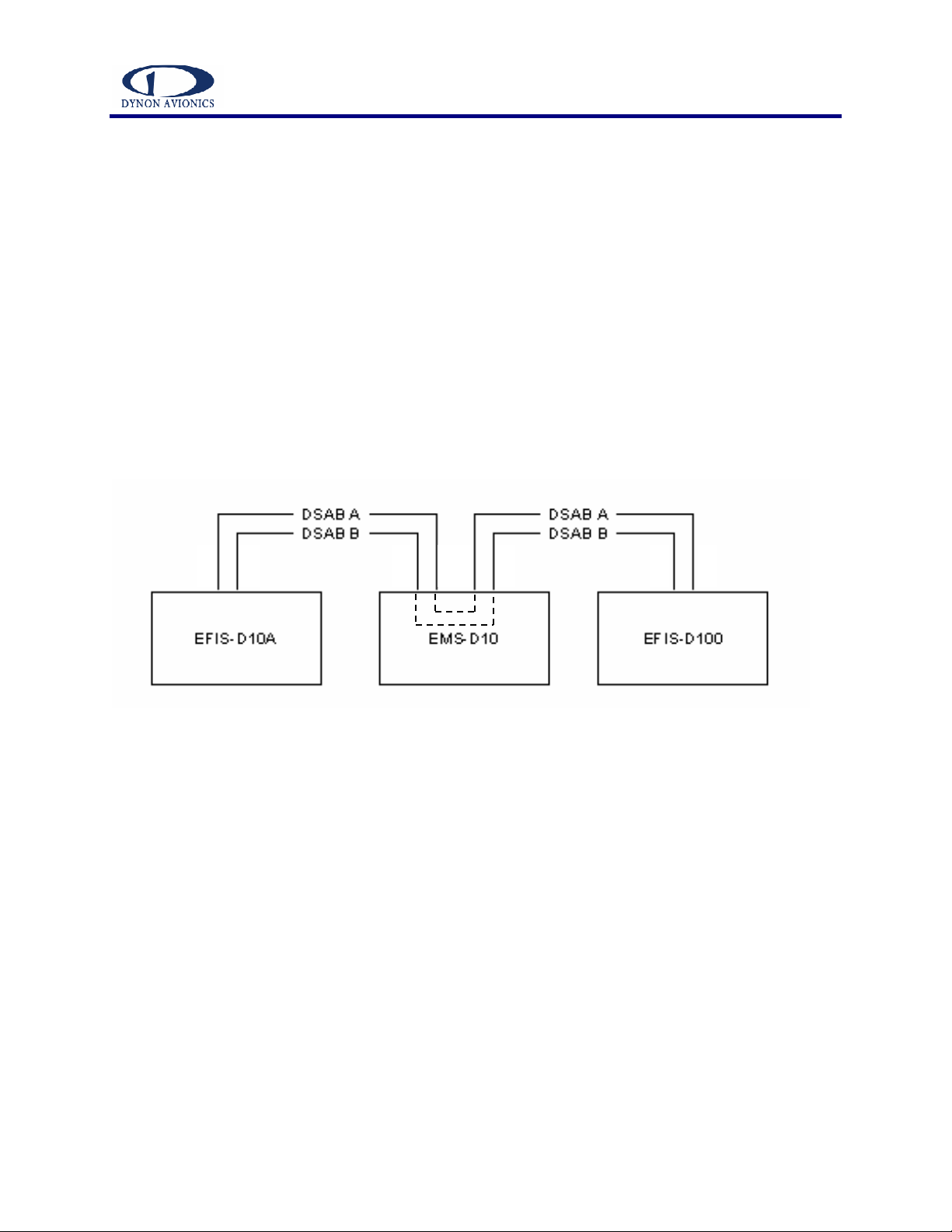
1-/0 *23-3./+4/%/+& 337
The Dynon Smart Avionics Bus allows for communication between a wide variety of products.
This communication will allow features such as data sharing and alarm notification between
units. The EFIS-D10A, EFIS-D100, and EMS-D10 products all have the hardware to support
DSAB connections; software support is forthcoming and will be available via our website.
DSAB is a multi-drop bus, meaning several devices are connected to the same 2 wires. The ideal
configuration is shown in the diagram below. You must connect the DSAB A connection on the
EFIS-D100 harness to the DSAB A connection for the next device in the chain. Do likewise for
the DSAB B connection. Some products, like the EFIS-D10A and EFIS-D100, have only one
pair of DSAB connections on the back connector; other products, like the EMS-D10 have two
pairs. The EMS-D10 internally shorts the two B connections and the two A connections; the two
pairs of external connections are for wiring convenience only. If you have 3 devices in your
system, and one of them is an EMS-D10, you should have that in the middle of your wiring
scheme. This eliminates the need to splice two wires together.
Example wiring connection
pin
34
pin 3
5
pin
37
pin
36
pin
5
pin 4
pin
5
pin
4

EFIS-D100 Installation Manual
6
81/3.,3/*,,*3-
Note that an installation checklist is provided in the Appendix as a reference as you proceed
through the installation and calibration process. However, it is suggested that you still read this
section before installation.
378*
Adding any new instrument to an airplane requires the installer to be aware of its weight and
how that affects the overall weight and balance of the plane. The following are the weights of the
EFIS-D100 and the EDC-D10A.
•Installed EFIS-D100 ......................................2 lb 13.5 oz (1287 g).
•Installed EFIS-D100 + battery.......................3 lb 3.8 oz (1465 g).
•EDC-D10A ....................................................3.6 oz (102 g).
/,.*37-3*,,-.*3-'-*8'3/
When selecting a location for mounting the EFIS-D100, all of the following considerations need
to be taken.
•Avoid placing the unit near heater vents or any source of extremely hot or cold air. Keep
in mind that the air surrounding the unit during operation must be cooler than 50 °C for
proper operation.
•Plan a panel location that allows convenient viewing of the unit with no obstruction. For
optimal viewing conditions, the angle between your eyes and a line perpendicular to the
surface of the screen should be no greater than 20 degrees.
•When flying straight and level, the panel angle from vertical may not be greater than
+/- 30 degrees.
•The unit must be aligned as close as possible with the longitudinal and lateral axes of the
airplane.
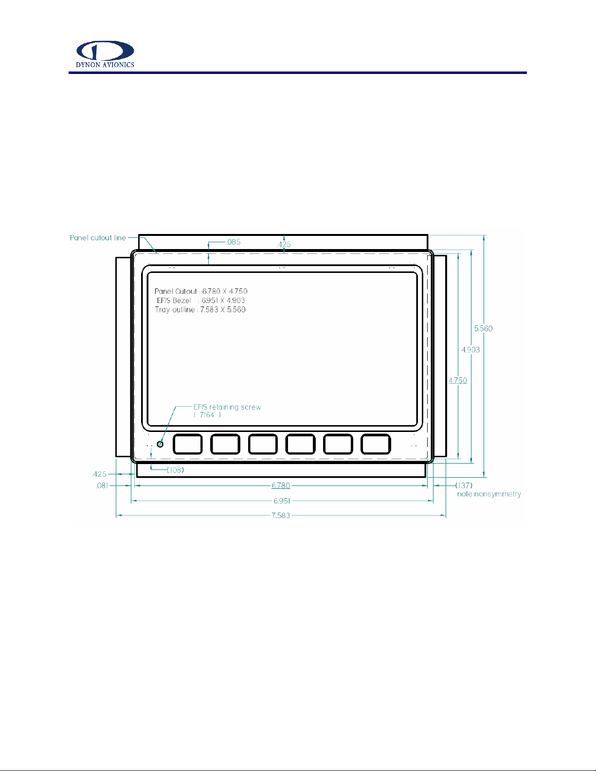
Please refer to the diagram on page 20 for the outside dimensions of the front bezel of the EFIS-
D100. Use these dimensions (in inches) to plan your panel for the space required by the unit.
EFIS-D100 Installation Manual
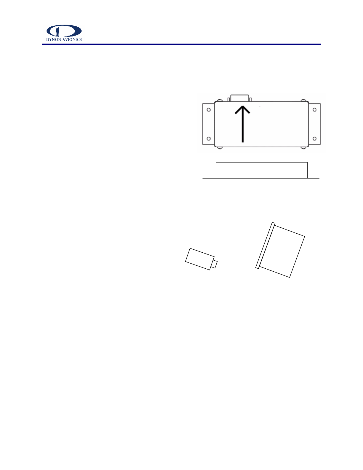
"
Connector forward and
tabs mounted down
EDC aligned within 1 degree of EFIS
mounting angle
/,.*379*,0 7*3.//--+,-.*3-
Finding a good location for this instrument is critical to an accurate EFIS-D100 heading display.
Keep in mind that calibration can compensate for small static magnetic fields superimposed upon
the earth’s field; it cannot take into account
dynamic effects like AC currents, non-constant DC
currents and non-stationary ferrous material (e.g. a
mechanical turn coordinator). Use the following
suggestions to help you find a good location for
your EDC-D10A.
•Keep the EDC-D10A away from any source
of magnetic fields (such as electrical
equipment and current-carrying wires) and
ferrous material.
oMove a handheld compass
throughout the space surrounding
your location to get a rough idea of
the suitability of your chosen
location. If the needle deviates significantly from true North in any given area,
that location would not be ideal
for the EDC-D10A.
•The EDC-D10A must be mounted such
that its orientation is as closely aligned
with the EFIS-D100 as possible. It
should be mounted with the long axis
parallel to the wings, the electrical
connector facing toward the front of the
plane, and the mounting tabs on the
bottom. The bracket used to hold the
EDC-D10A must account for all
differences in angles between the EFIS-D100 and the EDC-D10A. This includes pitch,
roll, and yaw. We recommend you use an electronic level that reads to 1/10
th
of a degree
to make sure the EDC-D10A is aligned with the EFIS-D100 in pitch, roll, and yaw to
better than 1 degree.
•All mounting hardware needs to be made from non-ferrous material such as aluminum,
plastic, or brass. Many stainless steel screws are alloys with some ferrous material in
them. If the item is attracted to a magnet, it should not be used in the installation. The
EDC-D10A needs to be mounted in a location as free from magnetic interference as
possible. This means keeping the EDC-D10A away from any ferrous nuts, bolts, and
screws, aircraft tubing, as well as from wires or devices carrying any appreciable current
such as strobe light wiring, autopilot servos, or other electronics.

EFIS-D100 Installation Manual
The EFIS-D100 attitude calculation
algorithm relies on data obtained via
the pitot and static lines. To ensure
proper unit operation, you must
connect these ports to the pitot and
static systems in your plane
.
.-.*37/**3.: 3*-*,3/
The AOA, pitot, and static ports on the back of the
EFIS-D100 are equipped with 1/8” NPT Female
fittings. To attach your pitot and static lines to the
back of the EFIS-D100, you must use standard 1/8”
NPT Male fittings at the end of each of the lines.
To install, simply T off your current static and pitot
lines to bring a line to the EFIS-D100. View the
following back view diagram the placement of your pressure lines.
Use a wrench to secure the mating pressure line fittings to the corresponding locations on the
back of the EFIS-D100. Do not over-tighten.
StaticPitot
AOA
EFIS-D100 Installation Manual
0 -4*373*-*8,
To mount the EFIS-D100, you must make a rectangular cutout in your panel. Ensure that the
dimensions of the cutout are: 6.780” wide and 4.750” tall. Place the EFIS-D100 mounting tray
behind the cutout. Secure it to your panel in whatever way you desire. Riveting it to the panel is
ideal, but drilling holes for mounting screws and nuts will work as well. Upon securing the
mounting rack to the back of your panel, slide the EFIS-D100 into it. Use a 7/64” Allen wrench
to secure the mounting screw (at the bottom left of the front bezel) into mounting rack. At your
discretion, you can also screw a #6-32 screw into the back of the mounting rack. See the diagram
above for location.

EFIS-D100 Installation Manual
.,3+*3-.-'374*3-
During manufacture, your EFIS-D100 underwent a comprehensive calibration, verification, and
burn-in routine that minimizes setup time and ensures that your EFIS meets Dynon's stringent
performance specifications. To account for your individual preferences and your aircraft's
particular setup, there are a few simple calibration and configuration steps that you must
complete before using your EFIS-D100.
This section will take you through a series of steps to make sure that you have properly installed
and configured your EFIS-D100. As in the User’s Guide, the term, “button #1” refers to the
leftmost button on the front panel of the EFIS-D100, “button #2,” the next button to the right,
and so on.
/437-3/*,,*3-
Turn your unit on by pressing button #1. Ensure that the screen is bright and readable and that all
instrument displays appear. If a desired display item is not present, refer to the User’s Guide to
use the CLUTTR feature to display the missing item.
/**37;-3*.8%3',378*&
CAUTION: It is your responsibility to fly your plane safely while performing any configuration
or calibration in flight. The best scenario would include a second person to perform any
necessary steps on the unit.
Once you are flying straight and level, press any button to bring up Main Menu 1. Press MORE
to display Main Menu 2. Press SETUP and then PITCH. Press INC or DEC until the horizon line
crosses through the center of the crosshairs. It is important that this be done while flying straight
and level to ensure proper pitch and roll display throughout all maneuvers. This pitch offset may
be used to zero the pitch display for panel tilt or whenever center of gravity or other effects
require.
*37*83.,3*3-%3&7,
In order to calibrate your EFIS-D100 heading, you must input your location’s current dip angle
into the EFIS-D100. Before doing this, you must obtain the dip angle (magnetic inclination) for
your geographic location:
1. Connect to the internet and point your browser to
http://www.dynonavionics.com/docs/inclination.html.
2. At that page you can input your ZIP code (in the US) or your latitude and longitude. If
you enter a ZIP code, you must click on “Get Location” to get the correct latitude and
longitude.
3. Once that data is entered, you must select “Compute Magnetic Field Values” at the
bottom of the page.
4. When the results are displayed, look at the angle next to the heading, “Inclination.” This
is your magnetic inclination.
Other manuals for EFIS-D100
4
Table of contents
Other Dynon Avionics GPS manuals

Dynon Avionics
Dynon Avionics FlightDEK-D180 User manual

Dynon Avionics
Dynon Avionics FlightDEK-D180 User manual

Dynon Avionics
Dynon Avionics DX15 User manual

Dynon Avionics
Dynon Avionics EFIS-D10A User manual

Dynon Avionics
Dynon Avionics EMS-D10 User manual

Dynon Avionics
Dynon Avionics EMS-D10 User manual

Dynon Avionics
Dynon Avionics SkyView SE User guide

Dynon Avionics
Dynon Avionics EFIS-D100 User manual

Dynon Avionics
Dynon Avionics SkyView User manual

Dynon Avionics
Dynon Avionics EMS-D120 User manual


