Dynon Avionics FlightDEK-D180 User manual

FlightDEK-D180
Installation Guide
This product is not approved for installation in type certificated aircraft
P/N 100600-000, Revision H
For use with firmware version 5.4
August, 2010
Copyright © 2003-2010 by Dynon Avionics, Inc.


Contact Information
Dynon Avionics, Inc.
19825 141st Place NE
Woodinville, WA 98072
Phone: (425) 402-0433 - 7:00 AM – 5:00 PM (Pacific Time) Monday - Friday
Fax: (425) 984-1751
Dynon Avionics offers online sales, extensive support, and continually-updated information on its products via its
Internet sites:
www.dynonavionics.com/support –Dynon Avionics primary web site; including:
docs.dynonavionics.com – Current and archival documentation.
downloads.dynonavionics.com – Software downloads.
support.dynonavionics.com – Support resources.
store.dynonavionics.com – Dynon’s secure online store for purchasing all Dynon products 24 hours a day.
wiki.dynonavionics.com – Dynon Avionics’ Documentation Wiki provides enhanced, extended,
continuously-updated online documentation contributed by Dynon employees and customers.
forum.dynonavionics.com – Dynon Avionics’ Internet forum where Dynon customers can interact and
receive Dynon technical support outside of telephone support hours. A key feature of the forum is that it
allows the exchange of diagrams, photos, and other types of files.
newsletter.dynonavionics.com – Dynon’s email newsletter.
blog.dynonavionics.com – Dynon’s blog where you can find new and interesting Dynon-related content.
Copyright
2003-2010 Dynon Avionics, Inc. All rights reserved. No part of this manual may be reproduced, copied, transmitted, disseminated or stored in
any storage medium, for any purpose without the express written permission of Dynon Avionics. Dynon Avionics hereby grants permission to
download a single copy of this manual and of any revision to this manual onto a hard drive or other electronic storage medium to be viewed for
personal use, provided that such electronic or printed copy of this manual or revision must contain the complete text of this copyright notice and
provided further that any unauthorized commercial distribution of this manual or any revision hereto is strictly prohibited.
Information in this document is subject to change without notice. Dynon Avionics reserves the right to change or improve its products and to
make changes in the content without obligation to notify any person or organization of such changes. Visit the Dynon Avionics website
(www.dynonavionics.com) for current updates and supplemental information concerning the use and operation of this and other Dynon Avionics
products.
Limited Warranty
Dynon Avionics warrants this product to be free from defects in materials and workmanship for three years from date of shipment. Dynon
Avionics will, at its sole option, repair or replace any components that fail in normal use. Such repairs or replacement will be made at no charge
to the customer for parts or labor. The customer is, however, responsible for any transportation cost. This warranty does not cover failures due to
abuse, misuse, accident, improper installation or unauthorized alteration or repairs.
THE WARRANTIES AND REMEDIES CONTAINED HEREIN ARE EXCLUSIVE, AND IN LIEU OF ALL OTHER WARRANTIES
EXPRESSED OR IMPLIED, INCLUDING ANY LIABILITY ARISING UNDER WARRANTY OF MERCHANTABILITY OR FITNESS
FOR A PARTICULAR PURPOSE, STATUTORY OR OTHERWISE. THIS WARRANTY GIVES YOU SPECIFIC LEGAL RIGHTS, WHICH
MAY VARY FROM STATE TO STATE.
IN NO EVENT SHALL DYNON AVIONICS BE LIABLE FOR ANY INCIDENTAL, SPECIAL, INDIRECT OR CONSEQUENTIAL
DAMAGES, WHETHER RESULTING FROM THE USE, MISUSE OR INABILITY TO USE THIS PRODUCT OR FROM DEFECTS IN
THE PRODUCT. SOME STATES DO NOT ALLOW THE EXCLUSION OF INCIDENTAL OR CONSEQUENTIAL DAMAGES, SO THE
ABOVE LIMITATIONS MAY NOT APPLY TO YOU.
Dynon Avionics retains the exclusive right to repair or replace the instrument or firmware or offer a full refund of the purchase price at its sole
discretion. SUCH REMEDY SHALL BE YOUR SOLE AND EXCLUSIVE REMEDY FOR ANY BREACH OF WARRANTY.
These instruments are not intended for use in type certificated aircraft at this time. Dynon Avionics makes no claim as to the suitability of its
products in connection with FAR 91.205.
Dynon Avionics’ products incorporate a variety of precise, calibrated electronics. Except for replacing the optional internal backup battery in
EFIS-based products per the installation guide, our products do not contain any field/user-serviceable parts. Units that have been found to have
been taken apart may not be eligible for repair under warranty. Additionally, once a Dynon Avionics unit is opened up, it will require calibration
and verification at our Woodinville, WA offices before it can be considered airworthy.


Table of Contents
Contact Information......................................................................................................................................................iii
Copyright......................................................................................................................................................................iii
Limited Warranty .........................................................................................................................................................iii
1. 1-1Introduction
OEM Installations...................................................................................................................................................... 1-1
Warning ..................................................................................................................................................................... 1-1
About this Guide........................................................................................................................................................ 1-2
Menu Descriptions..................................................................................................................................................... 1-2
2. 2-1Wiring Overview
Recommended Wiring Practices................................................................................................................................2-1
Power Requirements.................................................................................................................................................. 2-1
Grounding.................................................................................................................................................................. 2-2
+5V Excitation........................................................................................................................................................... 2-3
Thermocouple Harness Preparation........................................................................................................................... 2-3
Harness Mating.......................................................................................................................................................... 2-3
25-Pin Female EFIS Harness..................................................................................................................................... 2-4
37-Pin Female EMS Harness..................................................................................................................................... 2-7
25-Pin Male EMS Harness ........................................................................................................................................ 2-9
3. 3-1Transducer Installation
Tools and Equipment Required ................................................................................................................................. 3-1
Exhaust Gas Temperature (EGT) Probes................................................................................................................... 3-2
Cylinder Head Temperature (CHT) Probes ............................................................................................................... 3-3
Tachometer ................................................................................................................................................................ 3-4
Manifold Pressure Sensor.......................................................................................................................................... 3-5
Oil Pressure Sensor.................................................................................................................................................... 3-6
Oil Temperature Sensor............................................................................................................................................. 3-7
Fuel Pressure Sensor.................................................................................................................................................. 3-7
Fuel Flow Sensor....................................................................................................................................................... 3-9
Fuel Level Sensor .....................................................................................................................................................3-11
Ammeter Shunt.........................................................................................................................................................3-12
General Purpose Inputs.............................................................................................................................................3-13
Contacts ....................................................................................................................................................................3-18
General Purpose Thermocouple ...............................................................................................................................3-19
4. 4-1Instrument Installation
Selecting a Remote Compass Module Location ........................................................................................................ 4-1
EDC-D10A Communication Cable ........................................................................................................................... 4-2
Power Inputs.............................................................................................................................................................. 4-3
Serial Communication Cables ................................................................................................................................... 4-4
SL30 and/or GPS connection..................................................................................................................................... 4-6
Altitude Encoder Wiring ........................................................................................................................................... 4-8
External EMS Warning Light...................................................................................................................................4-10
Audio Alert Outputs .................................................................................................................................................4-10
Dynon Smart Avionics Bus (DSAB) Wiring............................................................................................................4-11
Panel Location and Mounting...................................................................................................................................4-13
Connecting Static & Pitot Lines ...............................................................................................................................4-14
5. 5-1EFIS Calibration and Configuration
Ensuring Proper Installation ...................................................................................................................................... 5-1
Setting Zero Pitch (In flight)...................................................................................................................................... 5-1
FlightDEK-D180 Installation Guide v

Table of Contents
vi FlightDEK-D180 Installation Guide
Compass Heading Calibration ................................................................................................................................... 5-1
Configure Airspeed Color Thresholds....................................................................................................................... 5-4
6. 6-1EMS Configuration
Full-Page Setup Menu Overview............................................................................................................................... 6-1
Alarm and Color Threshold Configuration................................................................................................................ 6-2
Global Parameters Setup ........................................................................................................................................... 6-3
Engine Type Configuration ....................................................................................................................................... 6-4
Fuel Level Calibration ............................................................................................................................................... 6-5
Trim Calibration ........................................................................................................................................................ 6-6
Flaps Calibration ....................................................................................................................................................... 6-7
Tachometer ................................................................................................................................................................ 6-8
Manifold Pressure...................................................................................................................................................... 6-8
Oil Pressure ............................................................................................................................................................... 6-9
Oil Temperature......................................................................................................................................................... 6-9
Exhaust Gas Temperature (EGT) .............................................................................................................................6-10
Cylinder Head Temperature (CHT)..........................................................................................................................6-11
Fuel Level.................................................................................................................................................................6-13
Fuel Pressure ............................................................................................................................................................6-13
Fuel Flow..................................................................................................................................................................6-14
Voltage .....................................................................................................................................................................6-15
Current......................................................................................................................................................................6-15
General Purpose Inputs.............................................................................................................................................6-16
Contacts ....................................................................................................................................................................6-18
General Purpose Thermocouple ...............................................................................................................................6-19
7. 7-1DSAB Configuration
Network Concepts ..................................................................................................................................................... 7-1
Example Networks .................................................................................................................................................... 7-2
Initial Setup ............................................................................................................................................................... 7-4
Brightness Configuration........................................................................................................................................... 7-5
Network Status .......................................................................................................................................................... 7-6
8. 8-1Autopilot Installation and Configuration
Additional Information and Updates ......................................................................................................................... 8-1
DSAB Firmware Compatibility................................................................................................................................. 8-2
Compass Calibration Critical For Certain AP Modes................................................................................................ 8-2
Autopilot System Electrical Installation .................................................................................................................... 8-3
Servo Mechanical Installation ................................................................................................................................... 8-6
AP74 Mechanical Installation...................................................................................................................................8-11
Firmware Upgrades Required For AP Functionality ................................................................................................8-13
AP Servo Configuration ...........................................................................................................................................8-14
AP74 Configuration..................................................................................................................................................8-30
9. 9-1Appendix
Appendix A: Ongoing Maintenance and Troubleshooting........................................................................................ 9-1
Appendix B: Dynon EFIS OAT Probe Installation and Usage.................................................................................. 9-7
Appendix C: HS34 Installation and Configuration...................................................................................................9-10
Appendix D: Dynon AOA/Pitot Installation and Calibration...................................................................................9-24
Appendix E: Encoder Serial-to-Gray Code Converter Installation...........................................................................9-32
Appendix F: Capacitance-to-Voltage Converter Installation....................................................................................9-35
Appendix G: Replacing the FlightDEK-D180 battery pack .....................................................................................9-36
Appendix H: Weights ...............................................................................................................................................9-36
Appendix I: FlightDEK-D180 Specifications...........................................................................................................9-38

1. INTRODUCTION
This manual provides information about the physical, electrical, and plumbing installation of the
FlightDEK-D180, EDC-D10A, optional AOA pitot probe, and all engine sensors purchased from
Dynon Avionics. Additionally, this guide deals with setting up the installation-dependant
firmware options. Because you may not have purchased all the components, you need only read
through the relevant sections of this guide. Information about the operation of this instrument
can be found in the FlightDEK-D180 Pilot’s User Guide.
The EFIS component of the FlightDEK-D180 uses solid-state sensor technology to give an
accurate and easy-to-understand display. To ensure accuracy in its readings, it is very important
that you install the instrument correctly and perform the specified calibration steps. This
installation guide helps you through that process.
OEM Installations
If your FlightDEK-D180 is installed by an OEM distributor, you may find that you are unable to
access some menus and settings. Some Dynon distributors customize various areas of the
FlightDEK-D180 firmware to maintain a consistent pilot experience and minimize integration
issues across a large number of installations. Currently, OEMs can customize access levels to the
following settings on Dynon systems: EMS GLOBAL setup menu, EMS SENSOR setup menu,
fuel calibration, trim calibration, flaps calibration, GPS/NAV setup menu, screen configurations,
data logging, and checklists/data panels. OEM distributors have the option of customizing some
or all of these areas. Please contact your aircraft’s manufacturer if you have any questions about
how your unit has been customized.
Warning
Dynon Avionics’ products incorporate a variety of precise, calibrated electronics. Except for
replacing the optional internal backup battery in EFIS-based products per the installation guide,
our products do not contain any field/user-serviceable parts. Units that have been found to have
been taken apart may not be eligible for repair under warranty. Additionally, once a Dynon
Avionics unit is opened up, it will require calibration and verification at our Woodinville, WA
offices before it can be considered airworthy.
FlightDEK-D180 Installation Guide 1-1

Introduction
1-2 FlightDEK-D180 Installation Guide
About this Guide
In the electronic (.PDF) version of this manual, page and section references in the Table of
Contents and elsewhere act as hyperlinks taking you to the relevant location in the manual. The
latest version of this manual is available on the Dynon Avionics website at
docs.dynonavionics.com.
The following icons are used in this guide:
Any text following this icon describes functionality available only with the HS34 HSI
Expansion Module connected to your system.
Any text following this icon describes functionality available only with the AP74
Autopilot Interface Module connected to your system.
Any text following this icon describes functionality that is possible when multiple Dynon
Avionics products are networked together via the Dynon Smart Avionics Bus (DSAB).
Any text following this icon refers to a setting or situation which merits particularly close
attention.
Menu Descriptions
Throughout this guide, the “>“ character is used to indicate entering a deeper level of the menu
system. For example, “EFIS > INFO > LEFT” indicates entering the EFIS menu, pressing
MORE, then pressing INFO, and then pressing LEFT to enter the left info item menu. Note that
the MORE button is not shown in the sequence, since pressing MORE reveals more options in
the same level of the menu system.

2. WIRING OVERVIEW
Please follow these instructions explicitly as improper wiring can result in permanent damage to
your instrument and/or the accompanying sensors.
All electrical power and EFIS-specific lines interface with the FlightDEK-D180 via the female
25-pin D-sub connector on the back of the instrument. All EMS-related sensor inputs enter the
FlightDEK-D180 via the male 37-pin and female 25-pin D-sub connectors on the back of the
instrument. Ensure that the unit powers on and that all indicators display expected values before
completing the final physical assembly.
Recommended Wiring Practices
For all electrical connections, use correct wiring techniques, taking care to properly
insulate any exposed wire. A short circuit between any of the wires may cause damage to
the FlightDEK-D180 and/or your aircraft. Make all connections to your harness before
plugging it into any of the components of the system. Do not make connections while
power is applied at any point in the system.
Dynon Avionics sells wiring harnesses for all connections to the FlightDEK-D180. The
harnesses are made up of 22 AWG wire and – with the exception of the thermocouple harnesses
– meet Mil Standard MIL-W-22759/16 (Tefzel insulation). If you have opted not to purchase
these harnesses, please refer to the provided wiring diagrams for construction information. We
recommend that all wire you use also meets Mil Standard MIL-W-22759/16; all wire supplied by
Dynon Avionics (with the exception of thermocouple wire, which uses FEP insulation) meets
this specification.
When using any pre-manufactured harness, verify that each pin has continuity with the expected
wire on the wiring diagram. This test can be easily done with a multimeter. When verifying
harnesses, use the wiring charts and diagrams in this guide as your ultimate authority on pin
function (for any harness) and wire color (for harnesses purchased from Dynon Avionics).
Route all wiring through the engine compartment such that there are no spots where it could
chafe or break. Use appropriate strain relief at all junctions between wires and connectors. We
recommend that you secure all wires at regular intervals along wiring runs to accommodate
vibration effects.
In the sections below, many connections have an
associated legend, as shown at right. All connections on
the EMS male 25-pin harness route to thermocouples and
are color-coded to correspond to the thermocouple
coloring. All connections on the EFIS female 25-pin harness are described in the 25-Pin Female
EFIS Harness section on page 2-4.
Pin Color Function
# Color function
Power Requirements
22 AWG wire is normally sufficient for the power supply and ground lines, but we recommend
that you consult a wire sizing chart and determine the size required for the wire routing in your
particular aircraft. Ensure that the power lines include a circuit breaker or an appropriately sized
FlightDEK-D180 Installation Guide 2-1

Wiring Overview
fuse for the wire you select. Power is fed to the FlightDEK-D180 via pins in the female D-25
connector as shown on the 25-Pin Female EFIS Harness diagram on page 2-4.
The FlightDEK-D180 system-wide power requirement is 14 watts typical and 19 watts
maximum. On a 12-volt system, this translates to about 1.5 amps of maximum current draw. On
a 24-volt system, this translates to about 0.8 amps maximum current draw. Normally, a 3-amp
circuit breaker or fuse is sufficient.
Grounding
Many of the engine sensors require a connection to a
shared electrical ground with the FlightDEK-D180. There
are many places on an aircraft where you could connect
these sensors. However, the ideal location to ground these
sensors is near the FlightDEK-D180 to minimize voltage
differences between the sensor and instrument grounds.
Some sensors (e.g., oil pressure and oil temperature)
connect to ground via their cases’ contact with the engine
or aircraft body. There must be a solid connection between
this “case ground” and the FlightDEK-D180 ground. The oil temperature sensor is very
susceptible to voltage differences between the engine case and the negative terminal of the
battery. Ensure that solid, thick electrical connections exist between the engine and battery
ground. Other sensors (e.g., fuel pressure) do not have a grounded case and have two leads
instead. One lead must be connected to ground, the other to the sensing input of the FlightDEK-
D180. The FlightDEK-D180 has 3 pins on the 37-pin harness which may be used for connecting
such sensors to ground. More than one sensor’s ground may be connected to any of these three
grounds using a splice.
EMS
DB37
Pin
Color Function
5 Black Ground
16 Black Ground
17 Black Ground
The case of the FlightDEK-D180 is connected to its supply ground. If your panel is connected to
aircraft ground, the connection between the instrument’s case and the panel dramatically helps
minimize voltage differences between the instrument and sensor grounds. If your panel is not
metal, or is otherwise isolated from engine ground, connect a 14 AWG or larger wire to the
instrument case. The most convenient place to do this is at the back of the mounting tray.
Additionally, connect any unused EMS ground leads to a convenient ground. Keep all ground
leads as short as possible.
Because of the current drawn by the FlightDEK-D180, even very small resistances between
battery ground and instrument ground can cause voltage differences which adversely affect
engine sensor readings. An easy way to test the quality of the instrument’s ground is to measure
voltage between the ground pin at the FlightDEK-D180 and the ground lead at your aircraft’s
battery. With the FlightDEK-D180 powered on, connect one lead of your voltmeter to a free
ground lead coming from the FlightDEK-D180. Connect the other lead of your voltmeter to the
ground terminal of your battery. The voltage between these two points should measure very
close to 0 mV (within 5 mV). If it does not, you must improve the ground connection between
the ground of your battery and that of your avionics bus.
2-2 FlightDEK-D180 Installation Guide
Wiring Overview
+5V Excitation EMS
DB37
Pin Color Function
18 White/red +5V
excitation
Some of the sensors require either a direct connection, or
connection via a resistor, to the +5V excitation circuit. We
recommend that you allow for more than one splice into
this line.
Thermocouple Harness Preparation
Refer to the 25-Pin Male EMS Harness section on page 2-9 during this procedure. Strip 1” of
brown outer insulation off each thermocouple wire pair on the supplied 25-pin thermocouple
harness. Strip ¼” of insulation from each of the thermocouple wires inside. Crimp the supplied
male Fastons onto each wire on the thermocouple harness. These will later be inserted into the
female Fastons on each thermocouple.
Do not connect the Fastons on the harness with those on the thermocouples until you have routed
the wires and mounted the thermocouples at the desired location.
The thermocouple wires can be cut to a desired length if your application requires. If you need to
extend the length of the thermocouple, you must use the correct type (J or K) thermocouple wire
to accomplish this. It is acceptable to use non-thermocouple fasteners to join two pieces of
thermocouple pair wire, provided the junction does not extend very far or have large temperature
differences across it. Please contact Dynon Avionics to order extension wire.
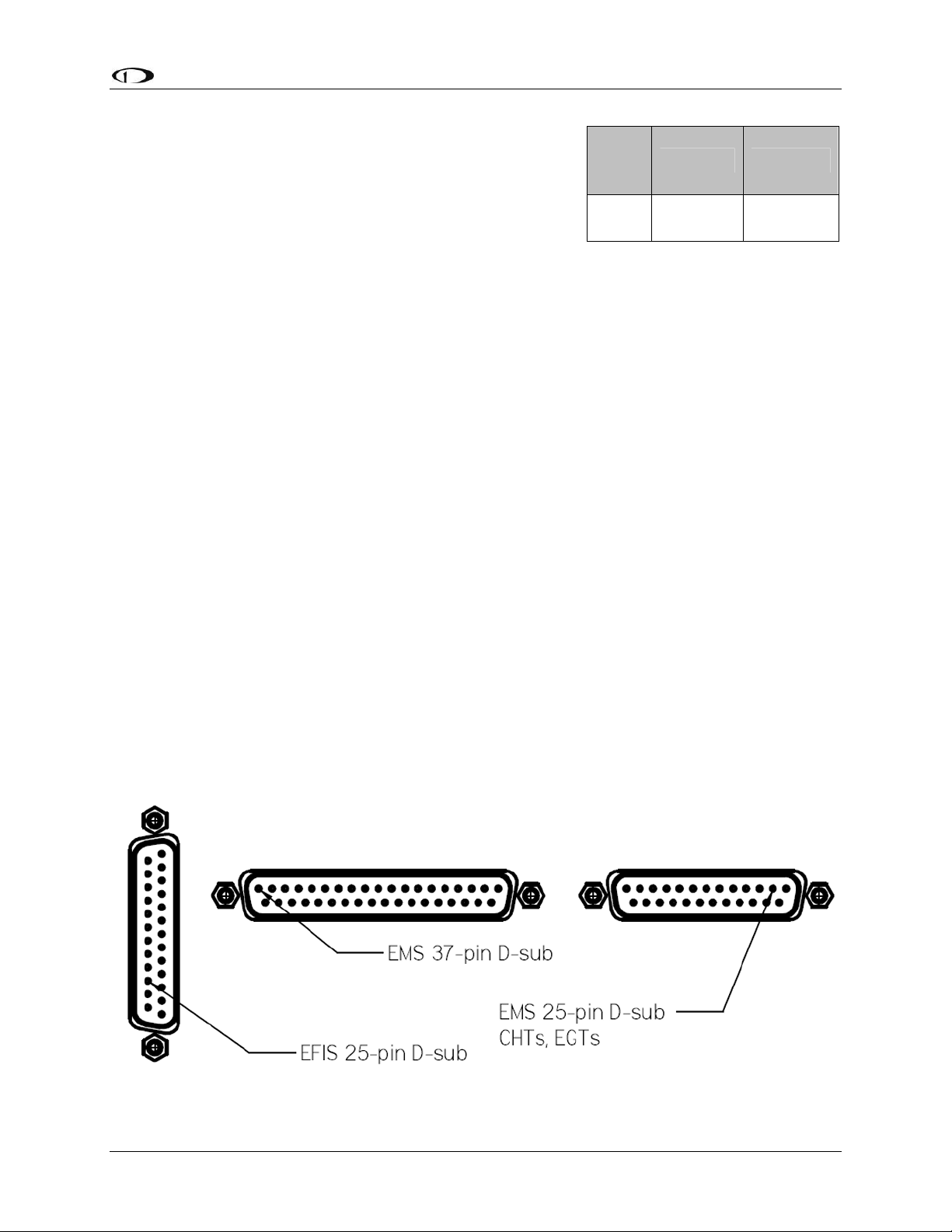
Harness Mating
The following diagram shows the 3 electrical connectors on the back of the FlightDEK-D180.
The two horizontal connectors are used for the EMS portion of the product; the vertical
connector is used for the EFIS portion. The main EMS harness (for all connections except EGT
& CHT thermocouples) should terminate in a 37-pin female D-sub connector. The EGT/CHT
thermocouple harness should terminate in a 25-pin male D-sub connector. The EFIS harness
(also used to provide power to the instrument) should terminate in a 25-pin female D-sub
connector. The following pages provide wiring diagrams and details for each of these harnesses.
FlightDEK-D180 Installation Guide 2-3

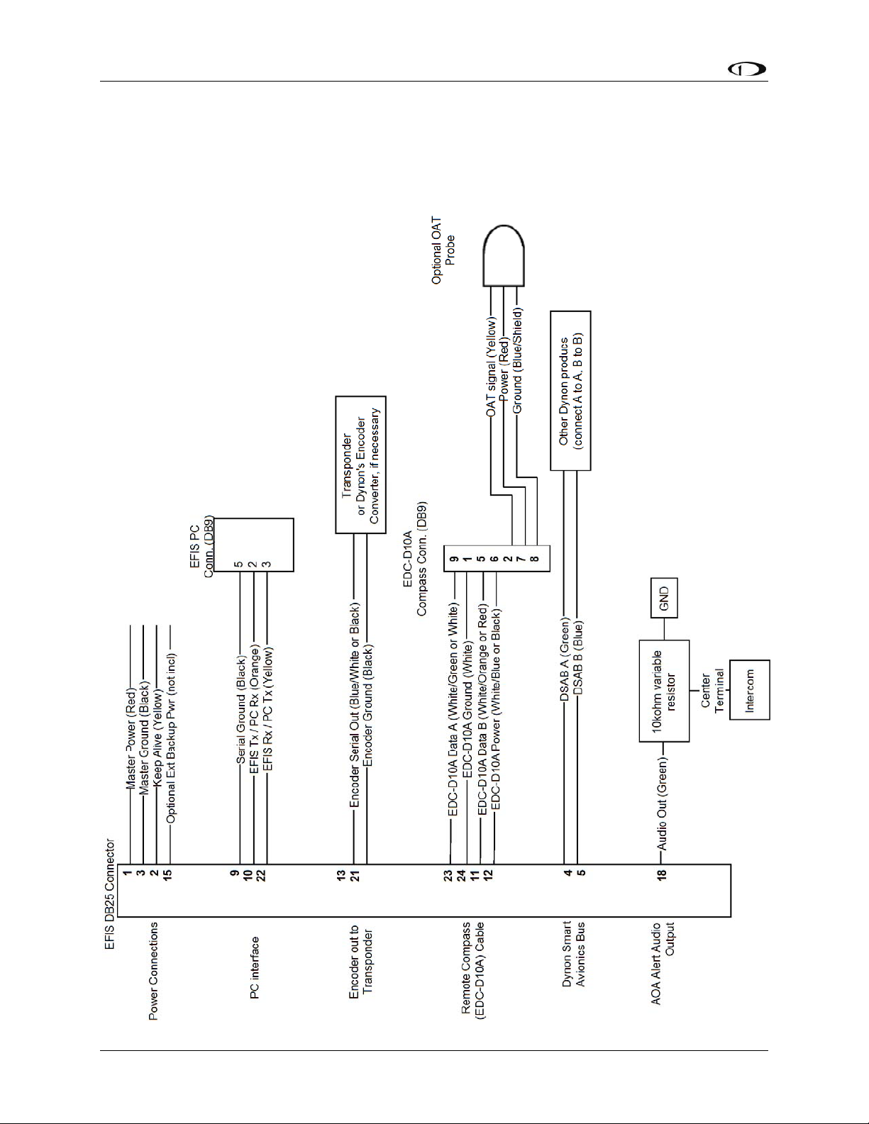
25-Pin Female EFIS Harness
Below is the wiring diagram of the EFIS 25-pin female harness. If you purchased your harness
from Dynon Avionics, it is color coded according to the chart on the following page. Unless
noted otherwise, all wires are 3 feet long on the Dynon-provided harness.
2-4 FlightDEK-D180 Installation Guide

FlightDEK-D180 Installation Guide 2-5
The pin assignments for the female 25-pin harness are repeated below. Note that the pin numbers
are labeled on the face of both the female and male connector. Each connection on the harness
supplied by Dynon is color-coded. These colors are listed in the following chart.
Female
DB25
Pin#
Dynon Harness
Wire Color Function Details
1 Red Master Power (10-30 volts) Page 4-2
2 Yellow Keep Alive Power (10-30 volts, always on) Page 4-2
3 Black Master Ground Page 4-2
4 Green DSAB-A Page 4-11
5 Blue DSAB-B Page 4-11
6 N/A No Connect
7 N/A No Connect
8 N/A No Connect
9 Black (bundled) PC Serial Ground – EFIS logging only Page 4-5
10 Orange (bundled)
FlightDEK-D180 Transmit / PC Serial
Receive (RS-232) – EFIS logging only
Page 4-4
11 White/Orange (Red
on some harnesses) EDC-D10A Data B Page 4-2
12 White/Blue (Black
on some harnesses) EDC-D10A Power (12V) Page 4-2
13 Blue/White (black
on some harnesses) Serial Encoder Transmit (RS-232) Page 9-32
14 N/A No Connect
15 N/A External Backup Power Page 4-2
16 Black Ground
17 N/A No Connect
18 Green Audio Alert Out Page 4-10
19 N/A No Connect
20 N/A No Connect
21 White (Bundled in
Encoder cable) Serial Encoder Ground Page 9-32
22 Yellow (Bundled)
FlightDEK-D180 Receive / PC Serial
Transmit (RS-232) – EFIS logging
Page 4-5
23 White/Green (Green
on some harnesses) EDC-D10A Data A Page 4-2
24 White EDC-D10A GND Page 4-2
25 N/A No Connect
Wiring Overview
WIRING SYSTEM OVERVIEW
The following block diagram depicts the basic layout of the EFIS DB25 electrical connections
and is for reference only. Read the specific instructions for each connection prior to installation.
The colors shown refer to the Dynon-supplied EFIS harness.
2-6 FlightDEK-D180 Installation Guide
Wiring Overview
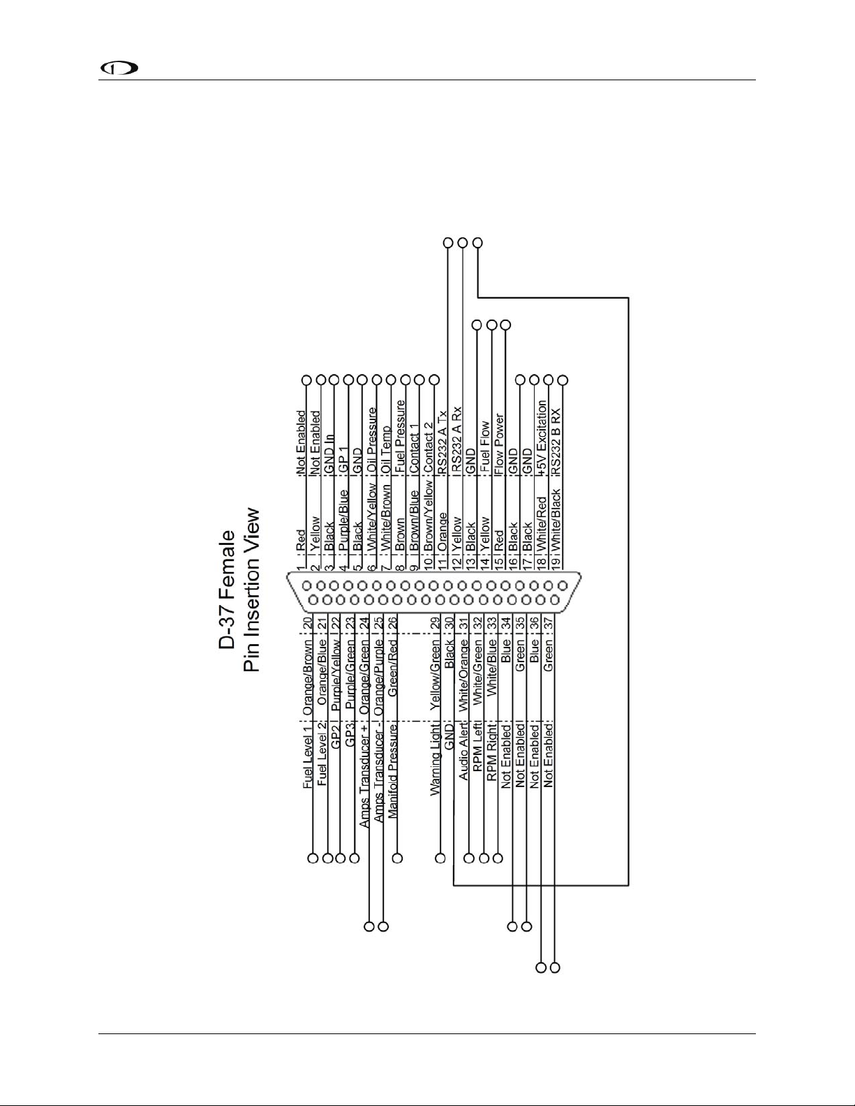
37-Pin Female EMS Harness
Below is the wiring diagram of the EMS 37-pin female harness. If you purchased your harness
from Dynon Avionics, pins 1, 2, 34, 35, 36, and 37 have wires inserted, but are not used. You
may clip the wires or remove the pins as needed. Refer to the following page for detailed pin out
descriptions.
FlightDEK-D180 Installation Guide 2-7

Wiring Overview
2-8 FlightDEK-D180 Installation Guide
The pin assignments for the female 37-pin harness are repeated below. Note that the pin numbers
are labeled on the face of both the female and male connector. Each connection on the harness
supplied by Dynon is color-coded. These colors are listed in the following chart.
DB37 harness
Pin# Dynon Harness
Wire color Function Details
1 Red Do not connect
2 Yellow Do not connect
3 Black Ground Page 2-2
4 Purple/blue GP 1 (general purpose resistive) Page 3-13
5 Black Ground Page 2-2
6 White/yellow Oil pressure Page 3-6
7 White/brown Oil temperature Page 3-7
8 Brown Fuel pressure Page 3-7
9 Brown/blue Contact 1 Page 3-18
10 Brown/yellow Contact 2 Page 3-18
11
Orange FlightDEK-D180 Transmit / PC Serial
Receive (RS-232) – EMS logging only
Page 4-5
12
Yellow FlightDEK-D180 Receive / PC Serial
Transmit (RS-232) – EMS logging only
Page 4-5
13 Black Ground (Fuel Flow) Page 3-9
14 Yellow Fuel flow input Page 3-9
15 Red Fuel flow power (12V) Page 3-9
16 Black Ground Page 2-2
17 Black Ground Page 2-2
18 White/red 5V excitation circuit Page 2-3
19 White/black Auxiliary Serial Receive (RS-232) Page 4-6
20 Orange/brown Fuel level 1 Page 3-11
21 Orange/blue Fuel level 2 Page 3-11
22 Purple/yellow GP 2 (General Purpose Resistive) Page 3-13
23 Purple/green GP 3 (General Purpose Resistive) Page 3-13
24 Orange/green Amps High Page 3-12
25 Orange/purple Amps Low Page 3-12
26 Green/red Manifold pressure Page 3-5
27 Not supplied General purpose thermocouple (J or K-type) Page 3-19
28 Not supplied General purpose thermocouple (J or K-type) Page 3-19
29 Yellow/green External warning light Page 4-10
30 Black PC Serial ground – EMS logging only Page 4-5
31 White/orange Intercom audio alert Page 4-10
32 White/green RPM left Page 3-4
33 White/blue RPM right Page 3-4
34 Blue Do not connect
35 Green Do not connect
36 Blue Do not connect
37 Green Do not connect
Wiring Overview
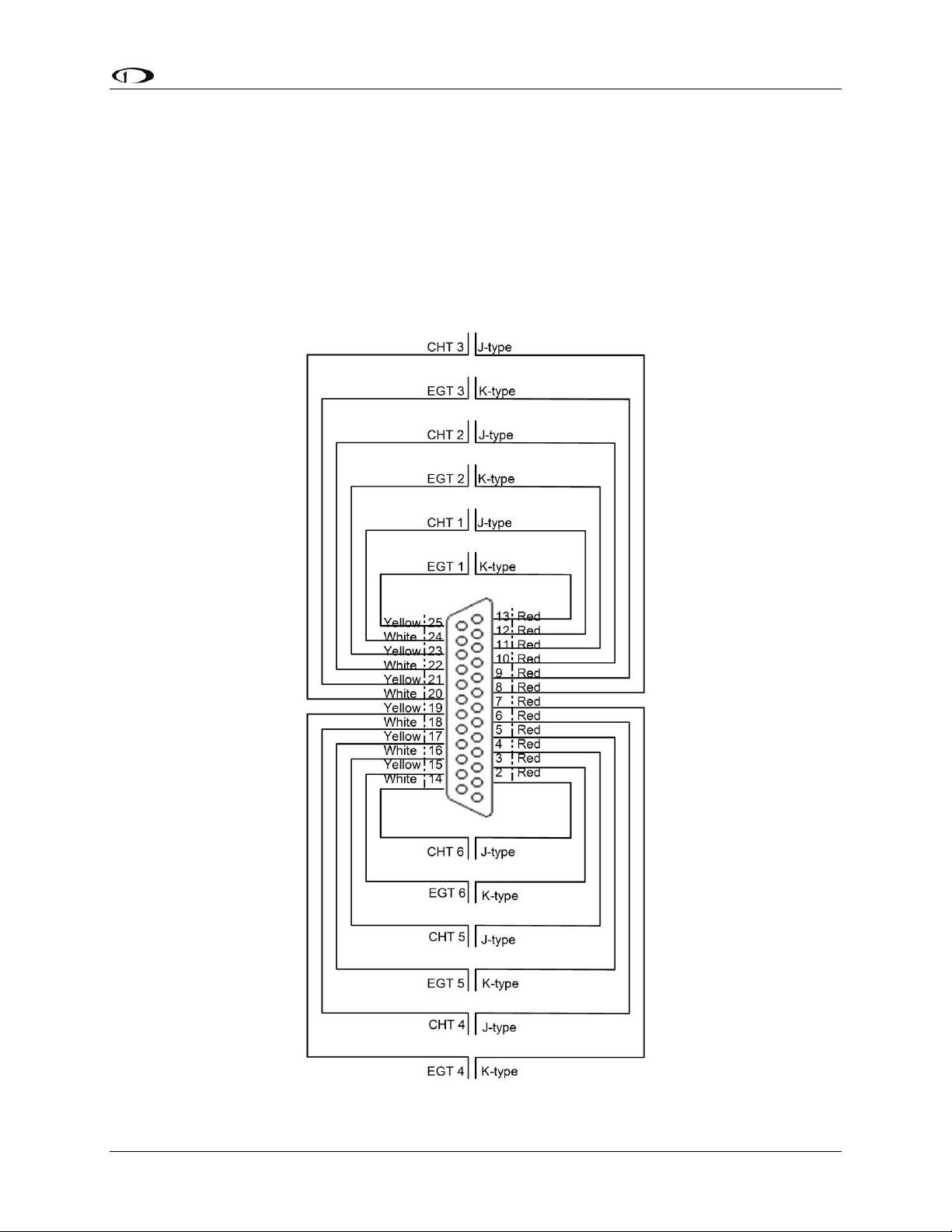
25-Pin Male EMS Harness
Below is the EMS 25-pin harness wiring diagram. The 4-cylinder harness only has EGTs 1
through 4 and CHTs 1 through 4 wired. The Rotax harness only has EGTs 1 and 2 wired, as the
EMS measures the Rotax-supplied resistive CHTs through its GP inputs. On the supplied
harness, each pair of wires is encased in brown insulation and labeled with corresponding
cylinder number. Inside the outer insulations, each wire in the pair has the color listed on the
diagram below. If you are making your own harness, utilize J & K type thermocouple wire as
indicated in the diagram.
FlightDEK-D180 Installation Guide 2-9


3. TRANSDUCER INSTALLATION
This section explains the steps required to install and connect all transducers supplied by Dynon
Avionics. Additionally, connection instructions are given for some transducers that Dynon
Avionics does not sell, like the tachometer, fuel level, flaps, trim, and contacts.
Tools and Equipment Required
The following list contains commonly used tools and equipment; however some of the tools or
equipment listed below may not apply to your installation.
Wire strippers
22 AWG wire (if harness not purchased or extending harness beyond 6 feet)
D-sub pin crimper
Faston/ring terminal crimp tool
oAvailable from www.bandcspecialty.com – (316) 283-8000 – part number RCT-1
Weather Pack crimp tool (common slip joint pliers will also work)
oAvailable from www.whiteproducts.com/tools.shtml
#2 Phillips screwdriver
Flathead screwdriver
¼” ID tubes, any necessary adapters, and clamps for routing manifold pressure to the
sensor.
Drill and 1/8” bit
FlightDEK-D180 Installation Guide 3-1

Transducer Installation
3-2 FlightDEK-D180 Installation Guide
Exhaust Gas Temperature (EGT) Probes
Correct placement of EGT probes on the exhaust manifold is critical to obtaining accurate
readings. Placement differs between engine types, and even specific models. Consult your
specific engine’s manual for proper EGT locations.
ROTAX ENGINES
For Rotax 912 engines, only two of the four cylinders are typically monitored for EGT. Unlike
the CHT probes which are mounted on diagonal cylinders, the EGT probes should be mounted
on the two rear cylinders’ exhaust manifolds. It is critical that the EGT probes be mounted to
parallel cylinders’ exhaust manifolds for proper temperature comparison.
ALL ENGINES
Once you have determined the appropriate EGT locations for your engine, drill 1/8” diameter
holes at the specified positions in the exhaust manifold. Usually, this spot is 2 to 8 inches from
the cylinder. This spot should be on a straight portion of the exhaust manifold, as this provides a
better fit for the hose clamps. For best results, mount all probes the same distance from each
cylinder.
1. Make sure the hole is placed to ensure that the probe does not interfere with the cowl or
spark plug. Also, when making holes, keep in mind that the probe could inhibit the ability
to perform routine maintenance if placed incorrectly.
2. Place probe in exhaust manifold, and secure it by tightening the clamp with a flathead
screwdriver. Make sure the clamp is tight and provides a secure fit, but do not over-tighten
such that visible stress is put on the pipe.
Now, plug each thermocouple wire into its corresponding wire on the thermocouple harness.
Ensure that you match the wire color pairs on the harness to those on the thermocouple. All
thermocouple harnesses supplied by Dynon have each function (e.g., CHT1, EGT1) labeled on
each thermocouple pair.
A loose probe could allow exhaust to leak. This can lead to carbon monoxide poisoning
in the cabin and/or a potential fire. Have a knowledgeable mechanic inspect the
installation.
The probe can come lose during flight, and could potentially come in contact with
rotating engine parts or the propeller. We suggest a safety wire to keep the probe in place.
Other manuals for FlightDEK-D180
1
Table of contents
Other Dynon Avionics GPS manuals

Dynon Avionics
Dynon Avionics SkyView SE User guide

Dynon Avionics
Dynon Avionics EMS-D120 User manual

Dynon Avionics
Dynon Avionics EFIS-D100 User manual

Dynon Avionics
Dynon Avionics SkyView User manual

Dynon Avionics
Dynon Avionics EMS-D10 User manual

Dynon Avionics
Dynon Avionics FlightDEK-D180 User manual

Dynon Avionics
Dynon Avionics EMS-D10 User manual

Dynon Avionics
Dynon Avionics DX15 User manual

Dynon Avionics
Dynon Avionics EFIS-D100 User manual

Dynon Avionics
Dynon Avionics EFIS-D10A User manual


