DynoSense DYNO 50 User manual

INSTRUCTION FOR USE
DYNO 50
All manuals and user guides at all-guides.com
all-guides.com

For support, please contact at +1-650-397-6103 or visit www.dynosense.com For support, please contact at +1-650-397-6103 or visit www.dynosense.com
2 3
DynoSense
DynoSense
1. INTRODUCTION
TABLE OF CONTENTS
2. INDICATIONS FOR USE
3. PRODUCT DESCRIPTION
Device
Thank you for purchasing the DynoSense Vital Sign Measuring
System. Please read the manual carefully before you use the unit,
and keep the manual after use.
The DynoSense Vital Sign Measuring System is intended to record,
transfer, store and display of single lead electrocardiography
(ECG), heart rate (HR), functional oxygen saturation of arterial
hemoglobin (SpO2), pulse rate (PR), respiration rate (RR), and oral
body temperature (TEMP). The device comes in contact with the
patient for approximately 60 seconds at each use. This system
is for spot checking and does not have continuous monitoring
capability or any alarm features.
This system is intended for patients 18 years and older in the
home environment. It is intended for use with patients who are well
perfused and during no motion condition.
This system makes no specific diagnosis. The device is for single
patient use. Users with implanted pacemaker and/or implanted
cardio-defibrillators (ICD) are not recommended to use the device.
The operation is based on capturing vital signs in response to a
single action from you. The device receives your thumb on the
metallic contact electrode, index finger inserted into the opening,
tongue above the thermometer tip, and mouth over the mouthpiece,
the vital signs data is captured and communicated to a mobile
device for forwarding to cloud for processing.
System Components
The DynoSense Vital Sign Measuring “System” comprises of
following components;
• Device
• Software (Mobile and Cloud Application)
• Accessories
INTRODUCTION 3
INDICATIONS FOR USE 3
PRODUCT DESCRIPTION 3
System Components 3
CONTRAINDICATIONS 5
SAFETY WARNINGS AND CAUTIONS 6
Warnings 6
Cautions 7
SETUP INSTRUCTIONS 8
What you need to get started 8
Unpack 8
HOW-TO-USE INSTRUCTIONS 8
Device Status Indicator 8
Proper device use 8
Download and Install the App 9
Complete Profile 9
Pairing the Devices 9
Capture Process 9
DYNOLIFERX DESCRIPTION 10
Measurement Page 10
Capture Page 10
Trend Page 11
Past History Result 11
CLEANING INSTRUCTIONS 12
CHARGING INSTRUCTIONS 12
STORAGE INSTRUCTIONS 12
SAFE DISPOSAL INSTRUCTION 12
TROUBLESHOOTING 13
MAINTENANCE 14
LIMITED WARRANTY 14
USER ASSISTANCE INFORMATION 15
GENERAL SAFETY INFORMATION 15
SPECIFICATIONS 15
GUIDANCE AND MANUFACTURERS DECLARATION 18
Electromagnetic Emissions 19
Electromagnetic Immunity 20
All manuals and user guides at all-guides.com

For support, please contact at +1-650-397-6103 or visit www.dynosense.com For support, please contact at +1-650-397-6103 or visit www.dynosense.com
4 5
DynoSense
DynoSense
The device is a battery powered, handheld, personalized, single
patient use vital sign measuring device. The device captures and
transfers;
• Single-lead electrocardiography (ECG) and heart rate (HR),
• Non-invasive measuring of functional oxygen saturation of arterial
hemoglobin (SpO2) and pulse rate (PR),
• Respiration rate (RR),
• Oral body temperature (TEMP).
The device uses Bluetooth Low Energy as the wireless link to enable
data transmission and communication to a mobile device. All the
acquired data by the device is encrypted with AES128 GCM. Acquired
data is wirelessly transmitted to the cloud using the mobile device.
Analyzed and archived data is available for remote monitoring by
authorized user(s).
The device accessories are;
• Charging Base - is used to charge the device via contact with device.
• USB Cable - is used to connect the charging base to a USB power
source.
• Alcohol Wipes - is used to sanitize the device prior and after each use.
• Glass Cover - is used to protect the mouthpiece from dirts and to turn
off the device.
To use the device, you will install an app (DynoLife) on your mobile
device. This app will initiate data collection for measurements, show
you a status during data collection, and tell you when data collection
is complete. The data collected by the DynoLife app will be transferred
to the cloud for analysis and storage, and will then be returned to your
mobile device for viewing.
Accessories
Software (Mobile and Cloud Applications) • Do not use this device if you have a pacemaker and/or implanted
cardio-defibrillators (ICD).
• Do not use the device if your left hand index finger or thumb or
tongue has cuts or open wounds.
• Do not use the device if you have trouble breathing normally.
• Do not use the device if you are under 18 years of age.
• Do not use the device if you are sensitive to Polycarbonate, UPS Class
VI material. This material has been tested for biocompatibility and has
been confirmed to be safe when it comes in contact with human tissue
but some individuals maybe hypersensitive to this material when they
become in contact.
• Do not share your device with others to avoid potential risk of
contamination.
ECG index
finger contact
LED status
indicator
thermometer
tip/ ECG tongue
contact
ECG thumb
contact
4. CONTRAINDICATIONS
SpO2
sensor
b.
c.d.
e.
a.
No. Part Number Name
a. 900-01113-01 Charging Base
b. 900-01100-01 Device
c. 360-01001-01 USB Cable
d. 300-01382-01 Alcohol Wipes
e. 900-01107-01 Glass Cover
mouthpiece
All manuals and user guides at all-guides.com

For support, please contact at +1-650-397-6103 or visit www.dynosense.com For support, please contact at +1-650-397-6103 or visit www.dynosense.com
6 7
DynoSense
DynoSense
Carefully read the following safety warnings and cautions before using
the system.
Warnings
• No modification to the System is permitted. PLEASE DO NOT
DISASSEMBLE.
• All components of the System should be kept out of the reach of children,
pets, or anyone who may be at risk of being harmed by components.
• This device is prescription use only.
• The device makes no diagnosis interpretation or treatment.
• Device is not provided sterile. Clean with alcohol wipe before each use.
• Product has not been tested for compatibility with exposure to Magnetic
Resonance Imaging (MRI) environment. Therefore it is not recommended to
use the device in Magnetic Resonance (MR) environment.
• When choosing a third party USB charging devices, select one that
complies with IEC 60950.
• The device is intended for single patient use, and is recommended to be
cleaned and sanitized with alcohol wipe between uses.
• Please ensure that 20 minutes has passed since last food/drink consumption
or strenuous activity prior to use.
SpO2,
• Pulse oximetry performance is adversely affected by excessive ambient
light, excessive motion, poor patient perfusion, fingernail polish on the left
hand index finger, anemia or low hemoglobin concentrations.
• Do not use if device optical sensor or LED is damaged or a sensor with
exposed electrical or optical components.
• If the index finger surface skin is damaged or discoloration, pulse rate
reading may not be accurate.
• Tissue damage can be caused by incorrect application or long duration of
use of an SpO2sensor.
• A functional tester cannot be used to assess SpO2 accuracy of the device.
ECG,
• Do not use this device during defibrillation.
• Interference from a non-grounded instrument near the patient can cause
problem with the waveform.
Temperature,
• Direct contact of the patient’s tongue with the thermometer tip is
required.
• Do not move the thermometer tip under the tongue during
the measurement. The thermometer tip should be placed
under the tongue at or close to sublingual pockets for accurate
measurements.
Respiration,
• Do not use the device if you have problem breathing normally.
• The device should not be used as an apnea monitor.
Cautions
• Keep System (device and case) away from excessive heat exposure,
as this may cause damage. Use the device in the recommended
operating conditions in the specification.
• If any component of System fails to operate after attempting all
suggested troubleshooting methods, contact your product provider
or distributor immediately.
• Do not dispose system parts in a household trash bin. Return parts
to DynoSense for disposal.
• Always store your device in the charging case when not in use.
• Do not drop the device.
• Do not immerse in water.
• Do not use while in bathtub or shower.
• Do not use soap or chemicals to clean the device.
• Do not turn power off during firmware update.
• The service life of the battery will depend on the conditions of use.
• The maximum range specified for bluetooth technology is about 10
meters.
5. SAFETY WARNINGS AND CAUTIONS
!
All manuals and user guides at all-guides.com

For support, please contact at +1-650-397-6103 or visit www.dynosense.com For support, please contact at +1-650-397-6103 or visit www.dynosense.com
8 9
DynoSense
DynoSense
Unpack
1. Open the packaging box.
2. Ensure the following is included in the box:
a. Device
b. USB Cable
c. Alcohol Wipes
d. Glass Cover
e. Charging Base
Device Status Indicator
Status Indicator Description
no light Battery off
Blinking Green
Device is ready for use
Blinking Red
Device is in firmware
update mode
Solid Blue
Device is connected
Solid Red
Device Fault. Please
contact support team
What you need to get started
• Device
• A smart mobile device with Bluetooth Low Energy capability and
internet connectivity
• Access to the computer USB port or USB power supply
6. SETUP INSTRUCTIONS
7. HOW-TO-USE INSTRUCTIONS
Complete Prole
a. If you already have an account, continue the process by
clicking “Login”.
b. If you do not have an account, click “Join DynoSense” to
set up a new account. Follow the instruction to complete the
profile.
Download and Install the App
Download and install DynoLife from the App Store or
Google Play. Sign up and follow the instructions on
the app to complete the process and log in.
Proper device use
1. Hold the device and insert LEFT hand index finger under the flap
until you feel the ridge at the end.
2. Place LEFT thumb on the bottom metallic contact.
3. Insert the thermometer tip under your tongue.
4. Close mouth around the mouthpiece.
5. Breathe naturally through your nose for about 60 seconds or until the
device vibrates. (Follow mobile app on-screen instructions)
Status Indicator
Pairing the Devices
Capture Process
1. Press “Capture” and follow
on-screen instructions to start a
new measurement.
2. Follow on-screen instructions
in case of an invalid capture.
Follow the on-screen instructions to
add a new device.
Measurement page
Capture
Trend page
6. Remove the device, rinse with water (see Section 9), shake for
a few seconds to allow any water in the device to come out.
7. Clean the device with alcohol wipe, and place it back into the
charging case.
8. PLACE THE GLASS COVER AND RETURN THE DEVICE TO
CHARGING BASE TO TURN OFF THE DEVICE.
Pair device
All manuals and user guides at all-guides.com

For support, please contact at +1-650-397-6103 or visit www.dynosense.com For support, please contact at +1-650-397-6103 or visit www.dynosense.com
10 11
DynoSense
DynoSense
Measurement Page
Capture Page
Data Interpretation (Heart Rate, Oral Temperature, Pulse Rate,
Respiration Rate, SpO2)
Data Interpretation (ECG Waveform)
The measurement page shows all
the health metrics. Each block
has:
1. Title - Symbol and name of
the metric
2. Value - Captured result
value for the metric
3. Favorite - Allow user to
prioritize the metric
The capture page shows the progress of a measurement with usage
feedback to you to ensure optimal signal is captured. You will receive
invalid capture page whenever there is an error during the caption
process.
1. Progress Indicator - Progress of each measurement
2. Usage Feedback - Feedback for you to correct the usage that
could potentially lead to incorrect measurements
You can view your measured result in detail by clicking the block.
You can view your measured ECG in detail by clicking the ECG chart.
Favorite
Value
Title
Progress
Indicator
Usage
Feedback
Capture result
Capture page Invalid Capture page
Range Bar
Range Table ECG Chart
Trend Page
Past History Result
You can monitor your daily, weekly or monthly health trend by
viewing the trend history.
View past history of your health metrics.
8. DYNOLIFE DESCRIPTION
Description
View past
history
Battery
Indicator
All manuals and user guides at all-guides.com
all-guides.com

For support, please contact at +1-650-397-6103 or visit www.dynosense.com For support, please contact at +1-650-397-6103 or visit www.dynosense.com
12 13
DynoSense
DynoSense
10. CHARGING INSTRUCTIONS
Make sure to place glass cover on device to keep the device off. The
device battery will gradually drain if the device is not covered.
The device with the glass cover should be stored in room temperature
and not exposed to excess heat.
9. CLEANING INSTRUCTIONS
Use alcohol wipe to clean the surface of the device. IPA (70% isopropyl
alcohol) based alcohol wipe packets should be used for cleaning.
Rinse ONLY the mouthpiece with warm water before and after every
use. Do not submerge in water. After rinsing, be sure to shake the
device for a few seconds for any water trapped in the mouthpiece to
drip out. Wipe the device with alcohol wipe afterward and before place
the glass cover.
Alcohol Wipe
Rinsing
11. STORAGE INSTRUCTIONS
Do not dispose the device in unsorted municipal waste. This device
should be returned to the distributor in case of damage.
12. SAFE DISPOSAL INSTRUCTION
Problem Possible Cause Solution
Device does
not turn on, no
status indicator
Low Battery Charge the battery and try again.
If the problem persists contact the
distributor.
No valid heart
rate/ECG on
result screen
(HR ----/ECG---)
No valid ECG data
collected
Try a new data collection/capture
by wetting your lips. Pay attention
to the on-screen data collection
progress indicator.
No valid
respiration rate
on result screen
(Resp Rate ----)
No valid
respiration data
collected
Breathe normally through the nose.
No valid SpO2
data on results
screen
(SpO2---)
No valid pulse
oximetry data
collected
Reinsert the left index finger under
the flap. Hold the device steadily
and gently without too much
pressure. Repeat the measurement.
Warm your finger prior to use.
Temperature
reading too low
Thermometer tip is
not making a good
contact or too
much movement
Repeat the measurement by
pressing tongue against the
thermometer tip. Do not move
the thermometer tip during the
measurement.
The App can’t
find the device
when trying to
add new device
Device is not on Make sure the device is taken out
from the charging base and is on.
Device status indicator should be
blinking green.
Bluetooth
connection failed
Mobile device
Bluetooth problem
Turn off and turn on the Bluetooth
of your mobile device.
“Can’t connect
to Cloud”
No server/
No internet
connection
1. Make sure you are connected to
the internet.
2. If the internet connection is not
good, please try again.
1. Plug the small end of the charging cable into the charging base,
and then plug the other end of the cable into a USB power supply or a
computer USB port.
13. TROUBLESHOOTING
Solid green
Device is powered and
fully charged
Solid orange
Device is charging
All manuals and user guides at all-guides.com

For support, please contact at +1-650-397-6103 or visit www.dynosense.com For support, please contact at +1-650-397-6103 or visit www.dynosense.com
14 15
DynoSense
DynoSense
14. MAINTENANCE
There are no repairable parts in this device. If the device is
inoperable after exhausting all the cases in the troubleshooting table
without resolution, contact the distributor using the information
provided in the “user assistance information“ section of this manual.
Make sure the device is cleaned properly after each use according to
the guidelines outlined in the cleaning section of this manual.
15. LIMITED WARRANTY
Subject to the conditions and limitations on liability stated herein,
the System as so delivered, shall materially conform DynoSense’s
current specifications for the System, for a period of one year
from the date of delivery. ANY LIABILITY OF DynoSense Corp.
WITH RESPECT TO THE SYSTEM OR THE PERFORMANCE THEREOF
UNDER ANY WARRANTY, NEGLIGENCE, STRICT LIABILITY OR
OTHER THEORY WILL BE LIMITED EXCLUSIVELY TO SYSTEM REPAIR,
REPLACEMENT OR, IF REPLACEMENT IS INADEQUATE AS A REMEDY
OR, IN THE OPINION OF DynoSense Corp.
Additionally, this warranty does not apply if:
2) The System is operated in a manner other than prescribed by
DynoSense Corp.
3) The System is operated in a manner that is not in conformance
with purchase specifications and specifications contained in the
System.
4) The System is not maintained in accordance with procedures
and processes defined in this Instruction for Use.
5) The System is repaired, altered, or modified in any way by
other than DynoSense Corp. authorized personnel, or without
DynoSense Corp. authorization. Contact DynoSense Corp. for
instructions and issuance of a Return Material Authorization if
claims under this warranty become necessary and if the System
or components of the System are to be returned. The System or
components will not be accepted for warranty purposes unless the
return has been authorized by DynoSense Corp.
The System or accessories purchased outside the original warranty
period are warranted for a period of 90 days, subject to all of
the restrictions contained in this Limited Warranty. Use of
unauthorized accessories may void the warranty. In all cases,
DynoSense Corp. will be the sole judge as to what constitutes
warrantable damage.
16. USER ASSISTANCE INFORMATION
17. GENERAL SAFETY INFORMATION
Please make sure you have reviewed the material in this user
manual in general and the troubleshooting section specifically. In
case you need further help please contact your local distributor
or DynoSense at +1-650-397-6103 or visit www.dynosense.com.
This section provides general information on the System.
Life of the Device:
• Service life of the device is based on battery: 18 months
• Shelf life of the device: 18 months
Recommendations:
• Frequency of device use shall be determined by your physician.
• Recommend periodic recharges the rechargeable battery, even
during storage, so that the battery will not discharge to an
unacceptably low voltage level, resulting in permanent damage.
Classifications
Degree protection against
electrical shock
Type BF Applied Part
Bluetooth 4.1 Wireless Technology Information
Modulation Type GFSK
Max. Output Power +4 dBm dBm
Frequency Range 2402-2480 MHz
Antenna Peak Gain 0 dBi
Recommended Range <10 meters, line-of-sight
Environment
Item Operating Storage
Temperature 10° to 40° C 10° to 40° C
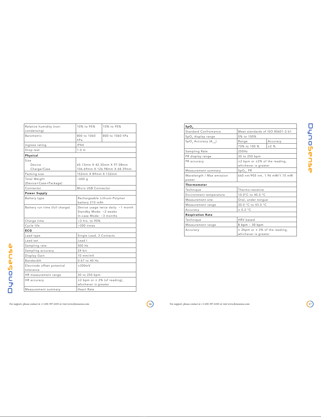
18. SPECIFICATIONS
All manuals and user guides at all-guides.com

For support, please contact at +1-650-397-6103 or visit www.dynosense.com For support, please contact at +1-650-397-6103 or visit www.dynosense.com
16 17
DynoSense
DynoSense
Relative humidity (non-
condensing)
10% to 95% 10% to 95%
Barometric 800 to 1060
hPa
800 to 1060 hPa
Ingress rating IPX4
Drop test 1.0 m
Physical
Size
Device
Charge/Case
65.13mm X 42.35mm X 97.08mm
106.69mm X 126.98mm X 68.39mm
Packing size 152mm X 89mm X 132mm
Total Weight
(Device+Case+Package)
~600 g
Connector Micro USB Connector
Power Supply
Battery type Rechargeable Lithium-Polymer
battery 210 mAh
Battery run time (full charge) Device usage twice daily: ~1 month
Standby Mode: ~2 weeks
In-case Mode: ~3 months
Charge time <3 hrs. to 90%
Cycle life >300 times
ECG
Lead type Single Lead, 3 Contacts
Lead set Lead I
Sampling rate 500 Hz
Sampling accuracy 24 bit
Display Gain 10 mm/mV
Bandwidth 0.67 to 40 Hz
Electrode offset potential
tolerance
±300mV
HR measurement range 30 to 250 bpm
HR accuracy ±2 bpm or ± 2% (of reading),
whichever is greater
Measurement summary Heart Rate
SpO2
Standard Confromance Meet standards of ISO 80601-2-61
SpO2display range 0% to 100%
SpO2Accuracy (Arms)Range Accuracy
70% to 100 % ±2 %
Sampling Rate 250Hz
PR display range 30 to 250 bpm
PR accuracy ±2 bpm or ±2% of the reading,
whichever is greater
Measurement summary SpO2, PR
Wavelength / Max emission
power
660 nm/905 nm, 1.96 mW/1.10 mW
Thermometer
Technique Thermo-resistive
Environment temperature 10.0°C to 40.0 °C
Measurement site Oral, under tongue
Measurement range 30.0 °C to 43.0 °C
Accuracy ± 0.2 °C
Respiration Rate
Technique HRV based
Measurement range 8 bpm – 30 bpm
Accuracy ± 2bpm or ± 2% of the reading,
whichever is greater
All manuals and user guides at all-guides.com

For support, please contact at +1-650-397-6103 or visit www.dynosense.com For support, please contact at +1-650-397-6103 or visit www.dynosense.com
18 19
DynoSense
DynoSense
19. GUIDANCE AND MANUFACTURERS DECLARATION
FCC:
FCC ID: 2AHYU-9990005001
IC: 21382-9990005001
FCC Part 15.19(a):
This device complies with part 15 of the FCC Rules. Operation is subject
to the following two conditions: (1) This device may not cause harmful
interference, and (2) This device must accept any interference received,
including interference that may cause undesired operation.
FCC Part 15.21:
Changes or modifications not expressly approved by the party
responsible for compliance could void the user’s authority to operate the
equipment.
FCC Part 15.105(b):
This equipment has been tested and found to comply with the limits for
a Class B digital device, pursuant to Part 15 of the FCC Rules. These
limits are designed to provide reasonable protection against harmful
interference in a residential installation. This equipment generates uses
and can radiate radio frequency energy and, if not installed and used
in accordance with the instructions, may cause harmful interference to
radio communications. However, there is no guarantee that interference
will not occur in a particular installation. If this equipment does cause
harmful interference to radio or television reception, which can be
determined by turning the equipment off and on, the user is encouraged
to try to correct the interference by one of the following measures:
• Reorient or relocate the receiving antenna.
• Increase the separation between the equipment and receiver.
• Connect the equipment into an outlet on a circuit different from that
to which the receiver is connected.
• Consult the dealer or an experienced radio/TV technician for help.
ISED RSS-Gen Notice:
(1) This device may not cause interference; and (2) This device must
accept any interference, including interference that may cause undesired
operation of the device.
1) l’appareil ne doit pas produire de brouillage; 2) l’appareil doit
accepter tout brouillage radioélectrique subi, même si le brouillage est
susceptible d’en compromettre le fonctionnement.
The ME Equipment is intended for use in the electromagnetic environment
specified below. The customer or the user of the ME Equipment should
assure that it is used in such an environment.
Emission Test Compliance Electromagnetic environment -
guidance
RF emissions
CISPR 11
Group 1 The device uses RF energy only for
its internal function. Therefore, its RF
emissions are very low and are not
likely to cause any interference in
nearby electronic equipment.
RF emissions
CISPR 11
Class B The device is suitable for use in all
establishments, including domestic
establishments and those directly
connected to the public low-voltage
power supply network that supplies
buildings used for domestic purposes.
Harmonic emissions
IEC 61000-3-2
Class A
Voltage
fluctuations/flicker
emissions IEC
61000-3-3
Complies
Electromagnetic Emissions
Frequency
range MHz
10m measuring distance 3m measuring distancea
Quasi-peak
dB(μV/m)
Quasi-peak
dB(μV/m)
30 to 230 30 40
230 to 1000 37 47
On a test site, class B equipment can be measured at a nominal
distance of 3m or 10m. A measuring distance less than 10m is allowed
only for equipment which complies with the definition given in 3.10.
At the transition frequency, the more stringent limit shall apply.
aThe limits specified for the 3m separation distance apply only to
small equipment meeting the size criterion defined in 3.10.
Radiated emissions limits and results:
EN/IEC 60601-1-2 Class B Limits below 1GHz
All manuals and user guides at all-guides.com

For support, please contact at +1-650-397-6103 or visit www.dynosense.com For support, please contact at +1-650-397-6103 or visit www.dynosense.com
20 21
DynoSense
DynoSense
Electromagnetic Immunity
The ME Equipment is intended for use in the electromagnetic environment
specified below. The customer or the user of the ME Equipment should assure
that it is used in such an environment.
Immunity
test
IEC 60601
test level
Compliance
level
Electromagnetic environment -
guidance
Electrostatic
discharge (ESD)
IEC 61000-4-2
±6kV contact
±8kV air
±8kV contact
±15kV air
Floors should be wood, concrete or
ceramic tile. If floors are covered with
synthetic material, the relative humidity
should be at least 30%
Electrical fast
transient/burst
IEC 61000-4-4
±2kV for power
supply lines
±1kV for input/
output lines
±2kV for power
supply lines
±1kV for input/
output lines
Mains power quality should be that
of a typical commercial hospital
environment
Surge
IEC 61000-4-5
±1kV differential
mode
±1kV differential
mode
Voltage
dips, short
interruptions
and voltage
variations on
power supply
input lines
IEC 61000-4-11
>95% dip for 0,5
cycle
60% dip for 5
cycles
30% dip for 25
cycles
>95% dip for 5
sec
>95% dip for 0,5
cycle
60% dip for 5
cycles
30% dip for 25
cycles
>95% dip for 5 sec
Mains power quality should be that
of a typical commercial or hospital
environment. If the user of our
product requires continued operation
during power mains interruptions, it
is recommended that our product be
powered from an uninterruptible power
supply or a battery
Power
frequency
(50/60Hz)
magnetic field
IEC 61000-4-8
3A/m 30A/m Power frequency magnetic fields should
be at levels characteristic of a typical
location in a typical commercial or
hospital environment
NOTE UT is the a.c. mains voltage prior to application of the test level.
Conducted RF
IEC 61000-4-6
Radiated RF
IEC 61000-4-3
3Vrms
150 kHz to 80MHz
3V/m
80MHz to 2,5 GHz
3Vrms
150 kHz to 80MHz
10V/m
80MHz to 2,5 GHz
Portable and mobile RF
communications equipment should
be used no closer to any part of the
device, including cables, than the
recommended separation distance
calculated from the equation applicable
to the frequency of the transmitter.
Recommended separation distance
d=1.2 √P
d=1.2 √P 80MHz to 800MHz
d=2.3√P 800MHz to 2.5GHz
Where P is the maximum output
power rating of the transmitter
in watts (W) according to the
transmitter manufacturer and d is the
recommended separation distance in
metres (m). Field strengths from fixed
RF transmitters, as determined by an
electromagnetic site survey, a) should
be less than the compliance level in
each frequency range. b) Interference
may occur in the vicinity of equipment
marked with the following symbol
NOTE 1 At 80MHz and 800MHz, the higher frequency range applies.
NOTE 2 These guidelines may not apply in all situations. Electromagnetic propagation is affected
by absorption and reflection from structures, objects and people.
a. Field strengths from fixed transmitters, such as base stations for radio (cellular/cordless)
telephones and land mobile radios, amateur radio, AM and FM radio broadcast and TV broadcast
cannot be predicted theoretically with accuracy. To assess the electromagnetic environment due
to fixed RF transmitters, an electromagnetic site survey should be considered. If the measured
field strength in the location in which the device is used exceed the applicable RF compliance
level above, the device should be observed to verify normal operation. If abnormal performance
is observed, additional measures may be necessary such as reorienting or relocating the device.
b. Over the frequency range 150kHz to 80MHz, field strengths should be less than 3V/m.
All manuals and user guides at all-guides.com
all-guides.com

For support, please contact at +1-650-397-6103 or visit www.dynosense.com For support, please contact at +1-650-397-6103 or visit www.dynosense.com
22 23
DynoSense
DynoSense
Symbol Title
IPX4 Protected against splashing water
Operating, storage and transport temperature
limit
Operating, storage and transport atmospheric
pressure limitation
Operating, storage and transport humidity
limitation
Operating instruction
Follow operating instruction
Non-ionizing radiation
Type BF applied part
No Alarms
Manufacturer
Do not dispose this product as unsorted
municipal waste
Recycle
Underwriters Laboratories
MEDICAL — PATIENT MONITORING EQUIPMENT
AS TO ELECTRICAL SHOCK, FIRE AND
MECHANICAL HAZARDS ONLY IN ACCORDANCE
WITH IEC 60601-1 (2012), “Medical Electrical
Equipment - Part 1: General Requirements for
Basic Safety and Essential Performance; CAN/
CSA-C22.2 No. 60601-1:08
CE Marking
MR unsafe, presents hazards in all MR
environments as device contains strongly
ferromagnetic materials.
Prescription ONLY.
+10℃
(+50 )
℉
+40℃
(+104 )
℉
1060hPa
800hPa
95%
10%
Recommended separation distances between
Portable and mobile RF communications equipment and device
The device is intended for use in an electromagnetic environment
in which radiated RF disturbances are controlled. The customer
or the user of the device can help prevent electromagnetic
interference by maintaining a minimum distance between portable
and mobile RF communications equipment (transmitters) and the
device as recommended below, according to the maximum output
power of the communications equipment.
Rated maximum
output power of
transmitter
W
Separation distance according to frequency of
transmitter
m
150 kHz to 80
MHz
d = 1,2√p
80 MHz to
800 MHz
d = 1,2√p
800 MHz to
2.5 GHz
d = 2,3√p
0.01 0.12 0.12 0.23
0.1 0.38 0.38 0.73
11.2 1.2 2.3
10 3.8 3.8 7.3
100 12 12 23
For transmitters rated at a maximum output power not listed
above, the recommended separation distance d in meters (m)
can be estimated using the equation applicable to the frequency
of the transmitter.Where p is the maximum output power rating
of the transmitter in watts (W) according to the transmitter
manufacturer.
Note 1: At 80 MHz and 800 MHz, the separation distance for the
higher frequency range applies. Note 2: These guidelines may not
apply in all situations. Electromagnetic propagation is effected by
absorption and reflection from structures, objects and people.
All manuals and user guides at all-guides.com

For support, please contact at +1-650-397-6103 or visit www.dynosense.com 24
DynoSense
P/N: 370-00115-01 Version: B August 2017
© Copyright 2017 DynoSense Corp. All right reserved.
European Authorized
Representative
Emergo Europe
Molenstraat 15
2513 BH The Hague
The Netherlands
Tel: (31) (0) 70 345-8570
Fax: (31) (0) 70 346-7299
DynoSense Corp.
100 Century Center Court, #650
San Jose, CA 95112, USA
All manuals and user guides at all-guides.com
Other manuals for DYNO 50
1
Table of contents
Other DynoSense Medical Equipment manuals
Popular Medical Equipment manuals by other brands

Orliman
Orliman MANUTEC M770 Instructions for use

Erbe
Erbe BiCision 20195-310 Instructions for use

Teleflex
Teleflex Arrow EZ-IO Instructions for use

Beka Hospitec
Beka Hospitec EVE! operating manual

Dräger
Dräger VentStar Basic 180 Instructions for use

OBH Nordica
OBH Nordica neck warmer 4008 Instructions of use