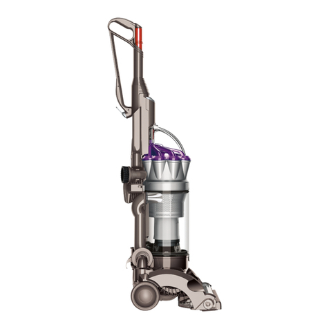
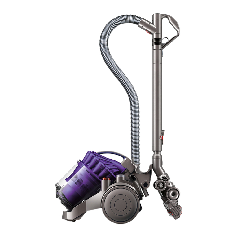
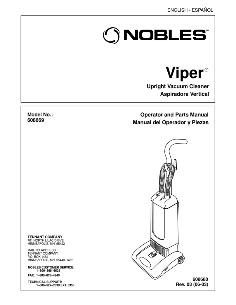
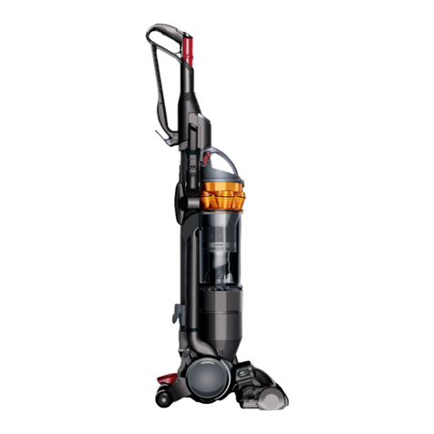
Dyson DC22 User manual

Service manual
Issued Jan 08


Service manual
Product overview Technical info. Fitting notes Parts recognition
General notes
Cable rewind replacement - removal
Cable rewind replacement - fitting
Switch & AC motor replacement - removal
Switch & AC motor replacement - fitting
Chassis, Satellite assembly, DDM assembly replacement - dismantle
Chassis, Satellite assembly, DDM assembly replacement - assemble
Sub-assemblies - Bin assembly
Sub-assemblies - Wand/hose assembly
Sub-assemblies - Turbine/Motorhead assembly
Electrical safety testing
AC wiring schematic (models with finger tip controls only)
AC electrical fault diagnostics (models with finger tip controls only)
DDM wiring schematic
DDM electrical fault diagnostics
DDM on-board diagnostics
Tuning (finger tip controls only)
Main body
Motor assembly
Hose, wand and floor tools
Cyclone and bin assemblies
Contents
This manual is written specifically for Dyson trained engineers and covers the full DC22
range. The service instructions assume the engineer has the approved tools and test
equipment with them.
Features 01
67
68
69
70
09
09
17
24
33
42
49
56
58
60
02
03
04
05
06
07
08
Page

Service manual
Product overview
Root cyclone technology is a unique system
that does not rely on filters or bags to separate
dirt from the air. Instead it uses powerful
centrifugal force to spin the dirt out of the air,
so there is no clogging and no loss of suction.
Combined with Dyson’s latest innovation - the
core separator - it’s more efficient at
removing microscopic dust than any other
cyclonic system.
Motorised brush head
Powerful bristles remove dirt and pet
hair. Uses toothed belt that doesn’t
slip or need replacing.
(Motorhead variants only).
It uses the latest digital vacuum
technology, so it produces zero
carbon emissions. It’s also
smaller and lighter than
conventional motors and is
protected by an intergrated, on
-board self-diagnostic system.
(DDM variants only).
Trigger bin-emptying
Just push the button to empty the
bin. No need to touch the dirt.
Telescope Wrap system
Hose and wand compress and wrap for easy carrying and storage.
dyson digital motor
Root cyclone technology
Doesn’t clog and doesn’t lose suction.
Dyson core separator
Combined with Root cyclone technology for increased
cyclone efficiency.
Fingertip controls
Operate the machine without bending down to reach
the controls.
(RF models only).
root cyclone
core separator
Shroud
Features
No other cyclone technology removes
more microscopic dust from the air flow
01

Service manual
Technical info.
Electrical safety testing
Ensure that at all times during the repair and testing of products
that customers, pets, children and you are not exposed to any
Live electrical supply.
Insulation test
The following tests must be performed
prior to and upon completion of all
repairs to Dyson floorcare products and
before any functional checks. You must
ensure that a full visual inspection
of the product is completed prior to
repair. These tests are vital to avoid any
possibility of personal injury to the end
user.
Test results
An insulation test reading of >2 MW
is acceptable.
A reading of below 2 MWis not considered
safe and further investigation, rectification
and testing must be completed before the
product is used. The following component
must be visually inspected:
Satellite assembly antenna.•
If you cannot repair a product with an
insulation test reading of below 2MW
you must inform the customer that the
product is unsafe to use.
Please inform the customer of the
required actions to repair the product
(including the charge structure).
If the product is left un-repaired please
indicate on your paperwork/hand held
device that the product is electrically
unsafe and attach a ‘WARNING:
product electrically unsafe’ sticker in
a visable location on the product.
02
The Seaward Primetest 200 (or equivalent)
should be used to test the electrical
insulation of a Class 11 appliance; it
indicates any electrical leakage.
Insulation test points:
Test the five screws highlighted in the
post filter housing.

Service manual
Technical info.
03
AC wiring schematic (models with finger tip controls only)
Cable
Rewind
ON/OFF
Switch
Motor
PCB
Assembly
EMC Satellite
Assembly
PCB
Brushbar
Motor
Brushbar
PCB
Power Wand
Hose Assembly
P1 P2
J7
J2
J2 J1
J1 J4
J4
SA1
J3
SA1
SA2
SA1
SA1
Motorhead
Floor Tool
Assembly
Antenna
L N
J3
J2
38
42
17
6
511
10
9
1412 13
Jockey
wheel
1615
Motor/PCB
Loom
Assembly
17
18

Service manual
Technical info.
04
No power to either motor
1. Check for damage/electrical failure to the plug and powercord.
2. Check the resistance across the fuse (UK only).
3. Check mechanical connection at points 1-8.
4. Check the resistance between the live pin on the plug and point 1.
5. Check the resistance between the neutral pin on the plug and point 2.
6. Check the resistance between points 1 and 8.
7. Check the resistance between points 2 and 7.
No power to the vacuum motor (brushbar motor operates)
1. Ensure that the motor wires are attached to points J2 and J4 of the PCB assembly EMC.
2. Ensure that the wires are attached to points 15 and 16 on the vacuum motor.
3. Check the resistance between points 3 and 16.
4. Check the resistance between points 4 and SA1 on the motor PCB.
5. Check the resistance between points SA2 on the motor PCB and 15.
6. Replace the Motor/PCB loom assembly.
7. Replace the motor.
8. Replace the satellite assembly.
No power to the brushbar motor (vacuum motor operates)
1. Check the resistance between points 9 and 12.
2. Check the resistance between points 10 and13.
3. Check the resistance between points 11 and 14.
4. Replace the Motorhead floor tool assembly and retest.
5. If after retesting the product the brushbar motor still does not work replace the satellite assembly.
Unable to turn on the product using the fingertip controls
1. Check the wand handle LED is illuminating when the buttons are pressed. If not, replace the
batteries.
2. If the LED is illuminating re-tune the wand handle to the machine (see page 8 for details).
3. Check that the Antenna is not damaged and is sufficiently attached to point SA1 of the satellite
assembly.
4. Replace the satellite assembly.
Brushbar operates in the stowed position or when lifted off the floor (Motorhead models only)
1. Replace the Motorhead floor tool assembly and retest.
2. If after retesting the product the brushbar still operates in the stowed position or when lifted off the
floor replace the satellite assembly.
Unable to turn on the product using the button on the main body
1. Check the mechanical actuation of the ON/OFF switch.
2. Check the resistance across the switch.
3. Check the resistance between points 17 and the relevant point on J2 of the satellite assembly.
4. Check the resistance between points 18 and the relevant point on J2 of the satellite assembly.
5. Replace the satellite assembly.
AC electrical fault diagnostic (models with finger tip controls only)

Service manual
Technical info.
05
DDM wiring schematic
Cable
Rewind
Switch/PCB
Assembly
DDM
PCB
Assembly
EMC
Satellite
Assembly
PCB
DDM
Opto
PCB
Brushbar
Motor
Brushbar
PCB
Power Wand
Hose Assembly
P1 P2
J7
J2
J2 J1
J1 J4
J4
SA1
J3
SA5
SA1
SA1
SA3SA4 SA2
SA6
J3
J2
DDM Assembly
Motorhead
Floor Tool
Assembly
Antenna
L N
J3
J2
38
42
17
6
511
10
9
1412 13
Jockey
wheel

Service manual
Technical info.
06
DDM electrical fault diagnostics
No power to either motor (power LED off)
1. Check for damage/electrical failure to the plug and powercord.
2. Check the resistance across the fuse (UK only).
3. Check mechanical connection at points 1-8.
4. Check the resistance between the live pin on the plug and point 1.
5. Check the resistance between the neutral pin on the plug and point 2.
6. Check the resistance between points 1 and 8.
7. Check the resistance between points 2 and 7.
No power to either motor (power LED illuminated GREEN)
1. Replace the satellite assembly and retest.
2. If the vacuum motor is not working after replacing the satellite assembly see the ‘No power to
the vacuum motor (brushbar motor operates)’ section below.
3. If the brushbar motor is not working after replacing the satellite assembly see the ‘No power
to the brushbar motor (vacuum motor operates)’.
No power to the vacuum motor (brushbar motor operates)
1. Ensure that the motor wires are attached to points J2 and J4 of the PCB assembly EMC.
2. Ensure all connections are correctly seated onto the satellite PCB.
3. Replace the satellite PCB.
4. Replace the DDM assembly.
No power to the brushbar motor (vacuum motor operates)
1. Check the resistance between points 9 and 12.
2. Check the resistance between points 10 and13.
3. Check the resistance between points 11 and 14.
4. Replace the Motorhead floor tool assembly and retest.
5. If after retesting the product the brushbar motor still does not work replace the satellite assembly.
Unable to turn on the product using the fingertip controls
1. Check the wand handle LED is illuminating when the buttons are pressed. If not, replace the
batteries.
2. If the LED is illuminating re-tune the wand handle to the machine (see page 8 for details).
3. Check that the Antenna is not damaged and is sufficiently attached to point SA1 of the satellite
assembly.
4. Replace the satellite assembly.
Brushbar operates in the stowed position or when lifted off the floor (Motorhead models only)
1. Replace the Motorhead floor tool assembly and retest.
2. If after retesting the product the brushbar still operates in the stowed position or when lifted off the
floor replace the satellite assembly.
Unable to turn on the product using the button on the main body
1. Replace the switch/PCB assembly.
2. Replace the satellite assembly.
3. Replace the DDM assembly.

Service manual
Technical info.
07
DDM on-board diagnostics
DDM variants of DC22 also include the following on-board diagnostics:
Green light: machine is healthy
Red light: machine is blocked. The machine should be
unplugged from the electrical outlet and checked for blockages.
Once the blockage is cleared the machine should be plugged
into the electrical outlet. The ON/OFF button will continue to
illuminate red. Once the machine is turned on the ON/OFF
button will change to green to indicate it is healthy.
Flashing Red/Green light: pre-filter is missing. If missing fit a
filter. If the pre-filter was present check the actuation of the pre-
filter microswitch when locating the pre-filter into the chassis. If you
can’t hear an audible click when locating the pre-filter replace the
DDM assembly. If an audible click is heard check the ribbon cable
is attached to point J2 on the satellite assembly. If the problem is
still present replace the satellite assembly.
No light: LED failure. Replace the switch/PCB assembly and
retest. If there is no light after replacing the switch/PCB assembly
replace the satellite assembly and retest. If there is no light after
replacing the satellite assembly replace the DDM assembly.
Flashing Red light: brushbar jammed (Motorhead model only).
The machine should be unplugged from the electrical outlet
and the motorhead floor tool checked for blockages. Once the
blockage is cleared the machine should be plugged into the
electrical outlet. The ON/OFF button will continue to flash red.
Once the machine is turned on the ON/OFF button will change
to green to indicate it is healthy.

Service manual
Technical info.
Tuning (finger tip control models only)
After replacing the wand handle assembly, handle cover assembly or satellite assembly it is
necessary to tune the relevant part with the corresponding part(s). Failure to tune the parts will result
in the machine not turning on when using the fingertip controls on the wand handle assembly.
The following sequence should be used to tune the product:
1.Plug the machine into the mains supply. On
DDM models the switch actuator will illuminate
green.
2. Press and hold the ON/OFF actuator on
the product.
After approximately 15 seconds the actuator will
flash red and green.*
Release the actuator.
*DDM products only. If tuning an AC product it
will be necessary to time the 15 seconds.
3. Press the ON/OFF button on the
wand handle assembly within ten seconds.
The actuator on the product will turn green.*
*DDM products only.
Pressing the ON/OFF button on the wand
handle again should start the product.
If the product does not start repeat the process.
15 secs
0
15
08

Service manual
Fitting notes
General notes
Disconnect the machine from the electrical outlet at all
times during repair and test. Failure to do so could
result in electric shock or personal injury.
All female terminal clips used in DC22 contain a locking
mechanism. The release pip will need to be activated before
separation from the male terminal can occur.
All screws used in DC22 are Torx T15 unless
otherwise stated.
Cable rewind replacement - removal
Recommended tools to repair DC22:
Torx T-8, T-10, T-15 and T-20 screwdrivers
Philips screwdriver
Large flat bladed screwdriver
Terminal screwdriver
Long/needle nosed pliers
01 Press the cyclone release catch
to remove the cyclone and bin
assemblies from the front of the
product.
Where this symbol is shown, ensure ESD protection
is used.
09
Wire colours may vary depending on territory.

Service manual
Fitting notes
10
02 Push the hose bracket release
catch to remove the hose and
wand assemblies from the front
of the product.
03 Undo the screw below the cyclone
release catch.
04 Slide the upper hose guide off the
chassis.

Service manual
Fitting notes
05 Undo the screw in the parking
yoke.
06 Remove the parking yoke from the
chassis.
07 Undo the screw in front of the
cable collar.
11

Service manual
Fitting notes
12
08 Pull the rear wheel and cap off the
side of the product.
09 Undo the three screws in the cable
rewind housing.
10 Unclip the cable rewind housing
from the side of the product.

Service manual
Fitting notes
11 Remove the cable rewind housing
from the side of the product.
12 Firmly press the catch to remove
the cable collar from the cable
rewind housing.
13 Open the cable collar and remove
from the cable rewind.
13

Service manual
Fitting notes
14
16 Carefully detach the cable rewind
fly leads from the terminals on the
PCB assembly EMC.
15 Force the cyclone inlet assembly
to one side. Release the satellite
assembly from the side of the
product.
14 Undo the short screw in the
satellite assembly.
Models with finger
tip controls only
Models with finger
tip controls only
Models with finger
tip controls only

Service manual
Fitting notes
17 Release the cable rewind from the
catch (catches on DDM products)
on the side of the product.
18 Release the cable rewind fly leads
from the retaining channels.
Remove the cable rewind.
15
Models with finger
tip controls only
Models without
finger tip controls
19 Detach the live wire from the
switch.

Service manual
Fitting notes
Models without
finger tip controls
20 Release the connection insulator
from the side of the product.
Open the insulator and detach the
neutral wires.
Remove the cable rewind.
16

Service manual
Fitting notes
Cable rewind replacement - fitting
17
Models without
finger tip controls
21 Ensure before fitting the cable
rewind that the fly leads are
twisted together and secured with
electrical tape as shown.
22 Ensure before fitting the cable
rewind that the motor leads and
ESD loom are neatly dressed
within the channels as shown.
Other manuals for DC22
7
Table of contents
Other Dyson Vacuum Cleaner manuals

Dyson
Dyson DC19 User manual

Dyson
Dyson Ball User manual

Dyson
Dyson DC17 Absolute User manual

Dyson
Dyson DC21 Motorhead User manual

Dyson
Dyson DC 22 User manual

Dyson
Dyson DC16 motorhead User manual

Dyson
Dyson DC15 User manual

Dyson
Dyson Slim DC18 User manual

Dyson
Dyson DC20 User manual

Dyson
Dyson DC41i MK2 User manual

Dyson
Dyson DC34 ANIMAL User manual

Dyson
Dyson DC23 CONTACT User manual

Dyson
Dyson DC19T2I User manual

Dyson
Dyson V11 User manual

Dyson
Dyson Ball Animal User manual

Dyson
Dyson BABy DC22 allergy User manual

Dyson
Dyson Slim User manual

Dyson
Dyson DC33 User manual

Dyson
Dyson DC26 User manual

Dyson
Dyson Ball User manual