Dytran Instruments VIBRACORDER 4400B Series User manual

Dynamic Transducers and Systems
21592 Marilla St. • Chatsworth, CA 91311 • Phone 818-700-7818
www.dytran.com • e-mail: [email protected]
OG4400BX
REV A, 02/17/2020, ECN 15327
OPERATING GUIDE
4400BX VIBRATION RECORDER

Dytran Instruments, Inc. 21592 Marilla St. Chatsworth, CA 91311 Phone: (818) 700-7818 Website: www.dytran.com email: info@dytran.com
Page | 2
Contents
I. Device Features.............................................................................................................................................3
II. Software Features .........................................................................................................................................3
III. Acronyms used in this manual ......................................................................................................................3
IV. Minimum System Requirements...................................................................................................................4
V. Installation.....................................................................................................................................................4
VI. Operation ......................................................................................................................................................5
VII. Mechanical configuration and mounting....................................................................................................11
VIII. Data recording considerations ....................................................................................................................11
IX. Serial Interface ............................................................................................................................................12
X. Time and Date Setup, MicroSD card method..............................................................................................13
XI. Recording Synchronization..........................................................................................................................14
XII. File Structure ...............................................................................................................................................14
XIII. Software License, Restrictions, and Disclaimer...........................................................................................16

Dytran Instruments, Inc. 21592 Marilla St. Chatsworth, CA 91311 Phone: (818) 700-7818 Website: www.dytran.com email: info@dytran.com
Page | 3
Dytran Series 4400BX is a vibration recorder with built-in 3-axes MEMS accelerometer capable of
recording acceleration in three orthogonal directions and writing the data on a microSD card. The
device comes in three configurations 4400B1 (+/-2g version), 4400B2 (+/-19g version), and 4400B3
(+/-200g version). The device features various operation modes: Free run, Time triggering, Level
Triggering, and Synchronized Triggering. The built-in RTC module allows accurate time stamp of the
recorded data.
I. Device Features
-System components:
4400BX vibration recorder
MicroSD card (Micro SDHC “SanDisk Extreme” with 32Gbytes data space is recommended)
Software Toolkit (stored on supplied Micro SDHC)
-4400BX is powered by a 3.7V rechargeable Li-Po battery.
-Micro USB charging, time setting, and Device information access.
II. Software Features
-Immediate data retrieval from the SD card to the PC
-Easy cursor operation for data selection, zoom, and cursor alignment
-One press of a button snapshot
-Data overlay
-Filtering
-Oversampling
-Time Synchronous Averaging
-FFT analysis
-Data export
III. Acronyms used in this manual
GUI - Graphical User Interface
FFT - Fast Fourier Transform
JPG - Joint Photographic File format
ASCII - American Standard Code for Information Interchange
TDMS - Technical Data Management Solution (Binary and ASCII file saving option for smaller file sizes
with stored header information)
UFF58 - Universal File Format 58 (purely binary file format for data recording)
MAT - MATLAB® Compatible data file

Dytran Instruments, Inc. 21592 Marilla St. Chatsworth, CA 91311 Phone: (818) 700-7818 Website: www.dytran.com email: info@dytran.com
Page | 4
IV. Minimum System Requirements
Desktop or a Laptop x86 based personal computer
Operating System: Windows 7/8/10 32-bit
CPU: Intel i3 or better
RAM: 1 GB
Hard Disk space: 1 GB
USB 2.0
Display Resolution 1280×780.
V. Installation
1. Run setup.exe
2. Click next to install drivers (if not already installed) and software.
Figure 1: Install Destination Directory
3. If asked, reboot your PC by clicking on “Restart”.

Dytran Instruments, Inc. 21592 Marilla St. Chatsworth, CA 91311 Phone: (818) 700-7818 Website: www.dytran.com email: info@dytran.com
Page | 5
VI. Operation
1. After the computer is restarted, the user will find the “9007 VibraCorder” icon in the Windows menu, as
shown in Figure below. A Shortcut will also be created on the Desktop for ease of access.
Figure 4: VibraCorder Icon.
Figure 5: 9007 Software
2. Insert the microSD card into the slot and launch the software.
3. Create configuration file – this tab allows the creation of the configuration file for the data acquisition.
3.1 It is recommended to format your microSD card before every use. Use the microSD card drive
navigation window to select the card and press “Format SD card” button.
3.2 Select data acquisition parameters:
allows for continuous recording which is started and stopped by the user pressing the
“Record” button.
acquisition records events defined by acceleration level. Prior to triggering the device
records 256 samples per axis of pre-triggered samples and 10,240 samples per axis of post triggered
samples. Each event is saved in separate files with the time stamp of the triggered event.

Dytran Instruments, Inc. 21592 Marilla St. Chatsworth, CA 91311 Phone: (818) 700-7818 Website: www.dytran.com email: info@dytran.com
Page | 6
is used to setup the trigger level
trigger source allows the selection of the axis to apply the triggering level to (or if “Any” is
selected the device will trigger if any of the axes cross the threshold)
Figure 6: Trigger source selection
selection allows the recording to start on a user selected time (any time up to 24 hours
into the future). User shall use the menu shown below to setup time (hours, minutes, and seconds) for
the recording to start
Figure 7: Trigger time selection
Five different sampling rates are available. See section on anti-aliasing filters to determine
the usable bandwidth of the measurements
Figure 8: Sampling rate selection
3.3 Select measurement file attributes:
selects the size of the measurement file.
Figure 9: File size selection

Dytran Instruments, Inc. 21592 Marilla St. Chatsworth, CA 91311 Phone: (818) 700-7818 Website: www.dytran.com email: info@dytran.com
Page | 7
The device will break the measurement into the files of approximate size selected by the user. Once
the collected data crosses over the threshold, the new file with the consecutive number is created.
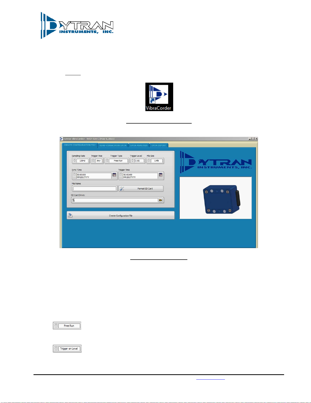
allows the user to name (4 characters allowed) the file. The full file name contains
8 characters. The first 4 are user selected (if nothing is selected, the generic word “TEST” is used). The
last 4 characters are the file counter “#000” followed by extension .TXT.
In this manner, the generic file name (if user selects nothing in the “File name” field) is “TEST#001.TXT”
thru “TEST#999.TXT”. If the name field is filled up as shown above, the file naming shall be
“abcd#001.TXT” thru “abcd#999.TXT”. The number of files allowed per single recording is 999. The
recording will stop, and the unit will shut itself down once this number is reached.
3.4 Setup synchronization time:
optional field that allows to set the time on the device’s RTC from the
microSD card. Select time and date desired to be set on the device (typical selection is couple of
minutes into the future that would allow to create config file, place the card into the device and start
the device in configuration mode)
3.5 After the desired acquisition parameters are selected, press “Create configuration File button”
3.6 Safely eject the microSD from the slot
4. Insert the microSD card into the 4400BX microSD card slot and, for normal operation, press the “Power”
button.
4.1 The firmware of the VibraCorder will verify the microSD card operation. The orange light of
“HARDWARE CHECK/READY” LED will blink several times checking various parameters of the card,
config file, and config file content. The orange light will stay blinking in accordance with the
troubleshooting table in the Appendix A if any errors are detected. Otherwise, the green light on the
“Recording” indicator shall lit. The green light will stay lit until the user presses “Record” button if
“Free run” or “Trigger on Time” modes are selected or will switch to blue immediately as the unit
starts sampling waiting for event. Although, multiple types of cards might be acceptable for use
with the VibraCorder, Dytran Instruments, Inc. recommends using MicroSDHC SanDisk Extreme
type.
5. Press “Record” button to start recording if using “Free run” mode.
5.1 The “RECORDING STATUS” LED will turn orange.
5.2 Press “RECORD” button to stop recording. The file with the acceleration data shall be closed, the device
will select next available file name and the device will return to the state described in 4.1 above.

Dytran Instruments, Inc. 21592 Marilla St. Chatsworth, CA 91311 Phone: (818) 700-7818 Website: www.dytran.com email: info@dytran.com
Page | 8
5.3 To start a new recording the user must press “Record” button again and the new file will be started. If
the test is complete, the MicroSDHC card can be removed from the device. It is recommended to shut
the power to the device before removing the card.
6. Insert the microSD card into PC and click on “READ VIBRACORDER DATA” tab.
6.1 Press “SD CARD DATA DOWNLOAD” button and navigate to the data file using explorer window. Double
click on the file and the software will ask if it’s ±2g, ±19g, or ±200g range and whether to preview the
display in metric units.
6.2 Each axis has a set of data manipulation buttons: “CURSOR HOME”, “TIME ZOOM”, “TO ANALYSIS”, and
“AUTOSCALE”. These buttons can be utilized for data examination and event selection.
6.3 Additional data files can be overlaid using “OVERLAY DATA” button. Once pressed, it will prompt the
user to select additional data files. If one data file is greater than another, the missing data will be
padded with 0s. “REMOVE DATA” button will remove the latest added data.
6.4 If one particular event is selected using cursors on any axis, the other two axis data for the same time
interval can be selected by the user using “ALIGN CURSOR TO X POSITION”, “ALIGN CURSOR TO Y
POSITION”, or “ALIGN CURSOR TO Z POSITION”.
6.5 Data snapshot can be taken in JPEG format for any axis using “SNAPSHOT” buttons.
6.6 The data table below shows the immediate cursor information for each axis: delta T, Frequency
(Calculated based on cursor positions when they are located on one period), RPM (Calculated based
on cursor positions when they are located on one period), and RMS value of the signal between cursors.
See Figure 10 for example:
Figure 10: Axis Z data of 100Hz sinusoidal vibration at 1 g RMS.

Dytran Instruments, Inc. 21592 Marilla St. Chatsworth, CA 91311 Phone: (818) 700-7818 Website: www.dytran.com email: info@dytran.com
Page | 9
6.7 “CLEAR PLOTS” button will clear all the data from the plots.
7. By pressing “TO ANALYSIS” button from any axis, the currently selected data between the cursors will
be exported to the “DATA ANALYSIS” tab with corresponding data from other two axes.
7.1 The software will prompt the user to either append data set or create a new one. This feature
allows comparison of two or more separate data sets. When Append is selected, the traces shall
be overlaid. When New is selected, all the previously displayed data shall be erased and substituted
with newly imported data set.
7.2 “RELOAD SELECTED DATA” button shall reload the original set of data into the analysis window.
7.3 “LOW PASS FILTER” and “HIGH PASS FILTER” buttons shall apply specified filter to the data, user
shall be prompted for corner frequency and filter order. Butterworth topology is used.
7.4 “SINGLE INTEGRATION” and “DOUBLE INTEGRATION” buttons will apply either single or double
numerical integration. The software shall automatically apply a high pass filter before performing
integration (to avoid any data run off). User shall be prompted for corner frequency of the filter.
7.5 “OVERSAMPLING” button shall perform non-linear interpolation on the data set, calculating
additional data point in between the existing one. The user will be prompted for the oversampling
frequency:
Figure 11: Same data set before and after oversampling with 32,000Hz frequency
7.6 “TIME SYNCHRONOUS AVERAGE” button shall perform time domain averaging on the set of data
using a user entered RPM value. The data set will be chopped using frequency from RPM window
and averaged with each other. The user shall be prompted for number of periods to display:

Dytran Instruments, Inc. 21592 Marilla St. Chatsworth, CA 91311 Phone: (818) 700-7818 Website: www.dytran.com email: info@dytran.com
Page | 10
Figure 12: TSA analysis results for 5 periods
7.7 “FFT ANALYSIS” button will perform Fast Fourier transform.
7.8 “PLOT VERTICAL UNIT” selector allows selection of acceleration units between English and Metric.
7.9 “RPM” control requires user input for TSA calculations and cursor location.
7.10 “PLOT HORIZONTAL UNITS” allows the change between Hertz, Orders, and RPM for FFT graph.
7.11 “GET RMS” button shall show the RMS signal value for each axis.

Dytran Instruments, Inc. 21592 Marilla St. Chatsworth, CA 91311 Phone: (818) 700-7818 Website: www.dytran.com email: info@dytran.com
Page | 11
8. “DATA EXPORT” tab allows the export of the data to conventional file formats: .csv, .mat, .tdms, .uff,
and .sqlite
8.1 User shall define the location of the file on the PC using the explorer.
8.2 If “EXPORT ALL RAW DATA” is checked, the software will export all the raw data from the
measurements file. If the “EXPORT ALL RAW DATA” is not checked, the software will export only
the content of the analysis screen.
VII. Mechanical configuration and mounting
1. Refer to 127-4400B drawing for physical dimensions of the device.
2. The mounting provisions consist of 2 mounting holes, 0.20” in diameter. Two 10-32 socket head screws
are supplied with the device. In order to mount the device, tap two 10-32 holes, 0.30” deep, 1.60”
apart per 127-4400B recommendation.
3. Alternative method of mounting is four magnets embedded into the mounting surface of the
VibraCorder.
VIII. Data recording considerations
The VibraCorder is designed to be powered with a rechargeable Li-Po battery. The minimum
continuous recording time is defined as 15 hours. The recording will be automatically broken down to
multiple files of the user selected size. No data shall be lost between files (internal buffer shall store
acceleration information during new file creation process). That means if the recorder is left in free
run or time triggered mode, it will record the data TEST#001.txt (in this example, the first four
characters of the file name are generic – if user selects nothing in the file name field during the
config.txt creation), then it will close TEST#001.txt, open new file TEST#002.txt and continue the
recording. It will execute that operation every time the specified file size is reached until it reaches
TEST#999.txt or the battery runs out. In case the battery runs out earlier than TEST#999.txt file name
is reached, the VibraCorder will close the current acquisition file and shuts itself down.
The tables below show LED troubleshooting codes for any possible issues during the start up:
Table 1: Possible startup issues:
orange light blinks:
0.1 sec
Insert the card
0.2 sec
Config file contains improper settings
0.5 sec
Config file not found
0.7 sec
Config file corrupted
1 sec
Incompatible card

Dytran Instruments, Inc. 21592 Marilla St. Chatsworth, CA 91311 Phone: (818) 700-7818 Website: www.dytran.com email: info@dytran.com
Page | 12
Table 2: File name issues
Blue left blinks
0.2 sec
File name overflow
0.5 sec
Improper run type
IX. Serial Interface
The device has a built-in serial interface for calibration and settings. Any terminal application can be
used to access the communication protocol. In order to access the settings mode, the following steps
must be taken:
1. Connect the device to a PC with terminal application installed. The device must be powered off
2. After the USB interface enumerates the device, check the device manager to identify the virtual
COM port number assigned to the device by the PC
3. Setup serial communication parameters as shown below
Figure 13: Serial baud rate settings
4. Press “Open” to open the terminal.
5. Press and hold “Record” button on the device while its powered off and press the “Power” button
6. Once the user releases the “Record” button, the terminal shall show the following menu:

Dytran Instruments, Inc. 21592 Marilla St. Chatsworth, CA 91311 Phone: (818) 700-7818 Website: www.dytran.com email: info@dytran.com
Page | 13
Figure 14: Serial baud rate settings
By following the menu options and instructions the user can display current time and date stored
on the device, setup new time and date, display current offsets and calibration factors, and
calibrate the unit using 1 g gravitational field.
X. Time and Date Setup, MicroSD card method
As it was mentioned in 3.4 above, there is a second method of setting up time and date on the
device. Using the config.txt file, the user can record the desired time and date setting on the
MicroSD card (usually one would record current date and time which is in near future – couple of
minutes ahead), and by following these steps transfer those settings into the device RTC:
1) Record time and date in the “Synchronous time” field of the SD card
2) Create config.txt file
3) Insert the card into the device while its powered off
4) Press and hold “Record” button
5) Press the “Power” button
6) Release the “Record” button. The “Recording” indicator should lit solid blue
7) Press “Record” button again
As the user performs step 7 from above, the “Synchronous” time from the card is recorded to the
RTC.

Dytran Instruments, Inc. 21592 Marilla St. Chatsworth, CA 91311 Phone: (818) 700-7818 Website: www.dytran.com email: info@dytran.com
Page | 14
Using this method, it is possible to synchronize two or more units. In order to do that, the same time
must be recorded into “Synchronous time” on two or more MicroSD card, the cards must be inserted
into the devices intended to be synchronized and the steps outlined above must be performed on
each device up until step 7. When all the devices intended for synchronization have the solid blue
light on (after step 6), the user must connect all the devices intended for synchronization with
synchronization cable and press the “Record” button on one of the devices. The synchronization
cable shall reproduce the button push on all the devices daisy chained together and the RTC timing
shall be synchronized.
XI. Recording Synchronization
The synchronization connector described above can also be used to synchronously start the
recording on multiple units. In order to do utilize this feature, the user must connect the units using
the synchronization cable, power them up (make sure the recording mode is free run on all the
units), and press “Record” button on one of the units connected.
XII. File Structure
The measurement file consists of two parts: the file header and the data. The header of the file
consists of 96 bytes and is at the beginning of the file. The header has the following structure:
Figure 15: File structure
The first 12 bytes of the header are reserved and shall be disregarded.
Bytes 12 thru 15 contain 4 user selectable characters for the file name
Byte 16 contains Sampling rate information and shall be decoded in accordance with the table below:

Dytran Instruments, Inc. 21592 Marilla St. Chatsworth, CA 91311 Phone: (818) 700-7818 Website: www.dytran.com email: info@dytran.com
Page | 15
Table 3: Sampling rate code
Bytes 17 and 18 contain Trigger level settings where byte 17 includes the whole part and byte 18 has
the decimal part of the level designation
Byte 19 has the triggering axis information
Table 4: Triggering axis
Byte 20 shows run type mode
Table 5: Run Type
Bytes 21 and 22 have battery level information at the beginning of the file creation. The 12-bit number
corresponds to the output of the ADC. The number has 2048 offset and can be converted to the actual
battery voltage using the following formula:
Vbat = (BatteryLevel – 2048)* 0.002170
Byte 23 is the file size designator

Dytran Instruments, Inc. 21592 Marilla St. Chatsworth, CA 91311 Phone: (818) 700-7818 Website: www.dytran.com email: info@dytran.com
Page | 16
Table 6: File size
Bytes 24 to 29 contain model and serial number information
Bytes 32 to 37 contain Synchronous Time settings
Bytes 48 to 53 contain Trigger Time settings
Bytes 38 to 45 and 54 to 57 contain offset and sensitivity information
The last three bytes of the header contain static verification code 0x08114Dh
Starting at byte 97 the user can access an actual sampled data. The sampled data comes in 8 byte
blocks with Byte 0 and 1 of each block being 0s, bytes 2 and 3 is the sampled data for axis X, bytes 4
and 5 is the sampled data for axis Y, and bytes 6 and 7 is the sampled data for axis Z. The sampled data
for each axis is 16-bit unsigned integer.
In order to display the data, the user must subtract the offset found in the header and divide by the
sensitivity value. The resultant double is the acceleration value.
XIII. Software License, Restrictions, and Disclaimer
LICENSE: The Dytran Instruments, Inc. (Dytran) 4400B VibraCorder™ software application (the
Software) available for download via the Dytran website, via email, or made available on portable storage
devices shipped with Dytran products is a free license for Dytran customers to use with Dytran products.
Dytran encourages you to know the possible risks involved in the download and use of software from
the internet. You are solely responsible for protecting yourself, your data, your systems and your
hardware used in connection with the Software. Dytran will not be liable for any damages suffered from
the use of the Software.
RESTRICTIONS: Neither the Software Licensee nor any Licensed User may rent or lease the Software.
Neither the Software Licensee nor any Licensed User may modify, reverse engineer, decompile or
disassemble the Software.
DISCLAIMER: BY USING THE SOFTWARE, YOU EXPRESSLY AGREE THAT ALL RISKS
ASSOCIATED WITH THE PERFORMANCE AND QUALITY OF THE SOFTWARE IS ASSUMED

Dytran Instruments, Inc. 21592 Marilla St. Chatsworth, CA 91311 Phone: (818) 700-7818 Website: www.dytran.com email: info@dytran.com
Page | 17
SOLELY BY YOU. DYTRAN SHALL NOT BE LIABLE FOR ANY DIRECT, INDIRECT, INCIDENTAL,
SPECIAL OR CONSEQUENTIAL DAMAGES ARISING OUT OF THE USE OF OR INABILITY TO USE
THE SOFTWARE, EVEN IF DYTRAN HAS BEEN ADVISED OF THE POSSIBILITY OF SUCH
DAMAGES.
THE SOFTWARE IS MADE AVAILABLE BY DYTRAN "AS IS" AND "WITH ALL FAULTS". DYTRAN
DOES NOT MAKE ANY REPRESENTATIONS OR WARRANTIES OF ANY KIND, EITHER EXPRESS
OR IMPLIED, CONCERNING THE QUALITY, SAFETY OR SUITABILITY OF THE SOFTWARE;
INCLUDING WITHOUT LIMITATION ANY IMPLIED WARRANTIES OF MERCHANTABILITY,
FITNESS FOR A PARTICULAR PURPOSE, OR NON-INFRINGEMENT. IN NO EVENT WILL DYTRAN
BE LIABLE FOR ANY INDIRECT, PUNITIVE, SPECIAL, INCIDENTAL OR CONSEQUENTIAL
DAMAGES THROUGH THE USE OF THE SOFTWARE HOWEVER THEY MAY ARISE AND EVEN IF
DYTRAN HAS BEEN PREVIOUSLY ADVISED OF THE POSSIBILITY OF SUCH DAMAGES.
This manual suits for next models
2
Table of contents