e-con Systems See3CAM 130 Parts list manual
See3CAM_130 Getting Started Manual 24-Oct-2016
www.e-consystems.com | Subject to change without notice Page 1 of 9
e-con Systems India Pvt Ltd
7th Floor, RR Tower – IV,
Super A-16 & A-17, Thiru-Vi-Ka Industrial Estate,
Guindy, Chennai - 600 032.
www.e-consystems.com
See3CAM_130
Getting Started Manual
Revision 1.0
Monday, October 24, 2016

See3CAM_130 Getting Started Manual 24-Oct-2016
www.e-consystems.com | Subject to change without notice Page 2 of 9
Contents
1 Revision History..................................................................................................................................... 3
2 Introduction............................................................................................................................................. 4
3 Scope.......................................................................................................................................................4
4 Disclaimer............................................................................................................................................... 4
5 Description.............................................................................................................................................. 4
6 Setting up the See3CAM_130............................................................................................................. 5
6.1 See3CAM_130 to PC Host Interconnecting Cable................................................................. 5
6.2 Connecting the board with Host................................................................................................. 6
6.2.1 Identification of USB3.1 GEN_1 Connector........................................................................6
6.2.2 Insertion of USB Cable in Connector...................................................................................6
6.2.3 Connecting the board to Host............................................................................................... 7
6.2.4 Ensuring the device connected to Host properly............................................................... 9
7 Conclusion.............................................................................................................................................. 9


See3CAM_130 Getting Started Manual 24-Oct-2016
www.e-consystems.com | Subject to change without notice Page 4 of 9
2 Introduction
The See3CAM_130 is a 13.0 Mega pixel, colour, UVC Compliant, USB 3.1 GEN1 SuperSpeed
Autofocus camera with Type C connector from e-con Systems, a leading embedded Product
Design Services Company which specializes in the advanced camera solutions. The
See3CAM_130 is a USB3.1 GEN1 SuperSpeed Autofocus camera product with reversible plug
and play Type C connector interface.
The See3CAM_130 is a 13.0 MP colour camera with Auto focus module. The See3CAM_130 is a
one-board solution containing Auto focus camera module with 1/3.2” AR1335 CMOS image
sensor from ON Semiconductor along with USB 3.1 GEN1 interface to the host PC, through
Type-A to Type-C legacy cable with reversible cable detection. See3CAM_130 can stream
uncompressed VGA@ 120 & 60 fps, HD@ 60 & 30 fps (720p60, 720p30), FHD @ 60 & 30 fps
(1080p60, 1080p30), 4K@ 15 & 7.5 fps (UHD & QFHD) UYVY formats. This can also stream the
uncompressed 13MP at 9 & 4.5 fps when connected to the USB 3.1 GEN1 host PC.
It also streams compressed MJPEG VGA@ 120 fps, HD@ 60 fps (720p60), FHD @ 60 fps
(1080p60), 4K (UHD & QFHD) at 30 fps UYVY formats. This can also stream the compressed
MJPEG 13MP at 20 fps. This See3CAM_130 is a UVC-compliant USB 3.1 GEN1 SuperSpeed
Camera with Auto-Focus that is also backward compatible with USB2.0 host ports and does not
require any special camera drivers to be installed in the host PC. When connected to USB2.0
host ports, the See3CAM_130 supports fewer resolutions and at lower frame rates.
The See3CAM_130 is UVC-compliant camera and it does not require any drivers to be installed
on the PC. The native UVC drivers of Windows and Linux Operating Systems shall be compatible
with this camera. e-con also provides the sample application that demonstrates some of the
features of this camera. However, this camera can be utilized any DirectShow application such as
Skype etc.
This document describes about how to connect the See3CAM_130 board with USB 3.1 GEN_1
host PC.
3 Scope
The scope of this document is limited to providing necessary overview of the See3CAM_130
camera board and how to use the same on a typical PC based environment.
4 Disclaimer
The specifications of See3CAM_130 camera board and instructions on how to connect this board
with PC are provided as reference only and e-con Systems reserves the right to edit/modify this
document without any prior intimation of whatsoever.
5 Description
The See3CAM_130 is a one board solution of size 80mm x 15mm. This camera board is based
on AR1335 Image sensor from ON Semiconductor along with Image Signal Processor (ISP) and,
has USB interface and the USB Type-C connector (Flip detection logic only). This See3CAM_130
is a Ready-to-Manufacture camera board with all the necessary firmware built in and compatible
with the USB Video Class (UVC) version 1.0 standard. Customers can integrate this camera in to
their products right away and this helps our customers to cut short the Time-to-Market. This

See3CAM_130 Getting Started Manual 24-Oct-2016
www.e-consystems.com | Subject to change without notice Page 5 of 9
camera board is USB Video Class compatible and this will work with the standard drivers
available with Windows and Linux. There is no need for any additional driver installation.
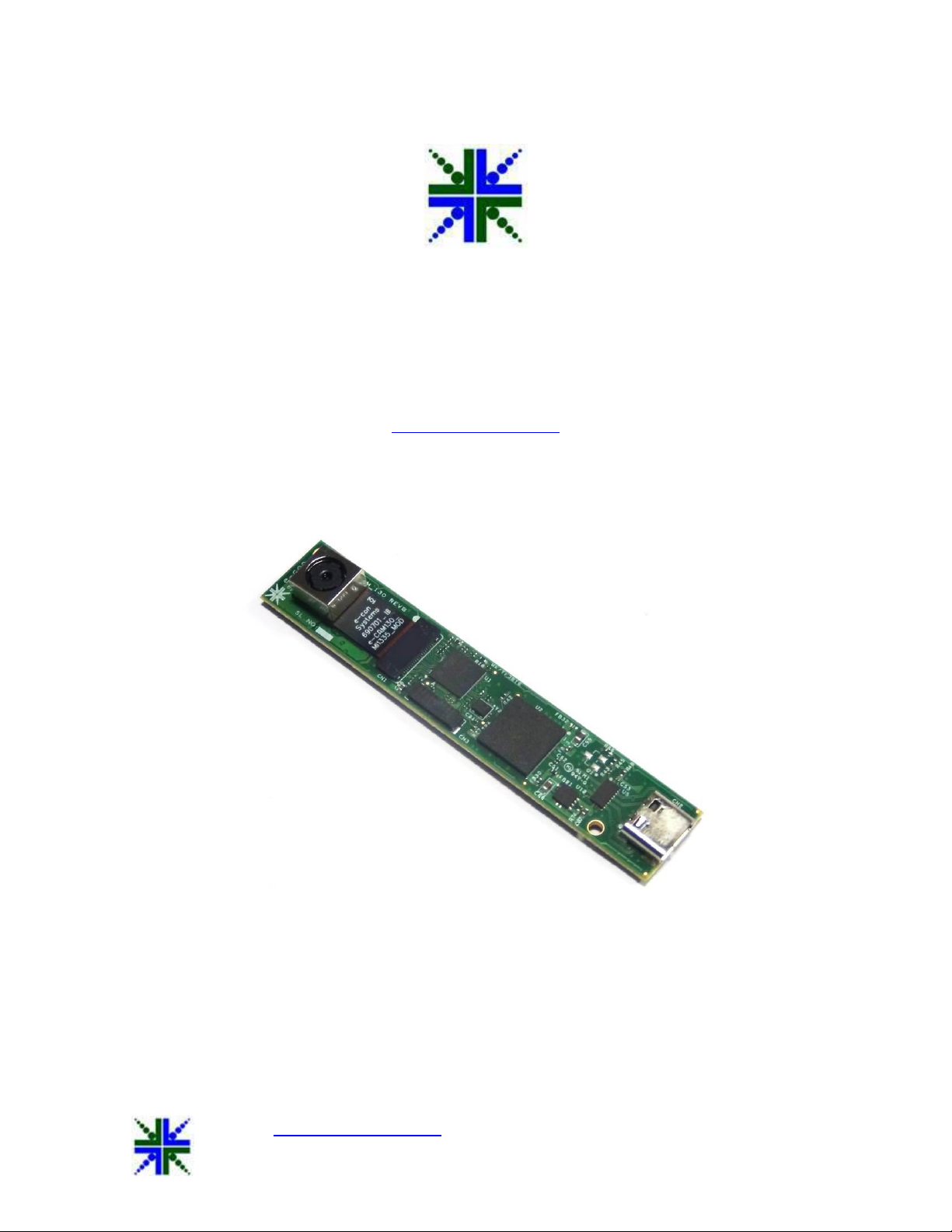
Figure 1: See3CAM_130
6 Setting up the See3CAM_130
This section describes how to connect the See3CAM_130 to the PC. The See3CAM_130 camera
is a USB 3.1 GEN 1 SuperSpeed client device. The See3CAM_130 camera is supplied along with
a USB 3.1 GEN 1 Type A to Type C cable to connect to the USB Type -A host port.
The following sections describe the parts supplied in the kit.
1. See3CAM_130 boards
2. USB3.1 GEN_1 Type A to Type C Cable
6.1 See3CAM_130 to PC Host Interconnecting Cable
The USB 3.1 GEN_1 A to Type C cable is used to connect See3CAM_130 camera board to the
PC will be supplied by e-con Systems.

See3CAM_130 Getting Started Manual 24-Oct-2016
www.e-consystems.com | Subject to change without notice Page 6 of 9
Figure 2: USB3.1 GEN_1 Cable
6.2 Connecting the board with Host
Please follow the below steps to connect See3CAM_130 board with PC or Laptop.
6.2.1 Identification of USB3.1 GEN_1 Connector
The location of USB Type C (CN2) connector on See3CAM_130 is shown in below figure
Figure 3: Location of USB3.1 GEN_1 Connector
6.2.2 Insertion of USB Cable in Connector
The USB3.1 GEN_1 Cable provided by e-con Systems should be inserted with USB Type C
connector as shown in below figure.
See3CAM_130 Getting Started Manual 24-Oct-2016
www.e-consystems.com | Subject to change without notice Page 7 of 9
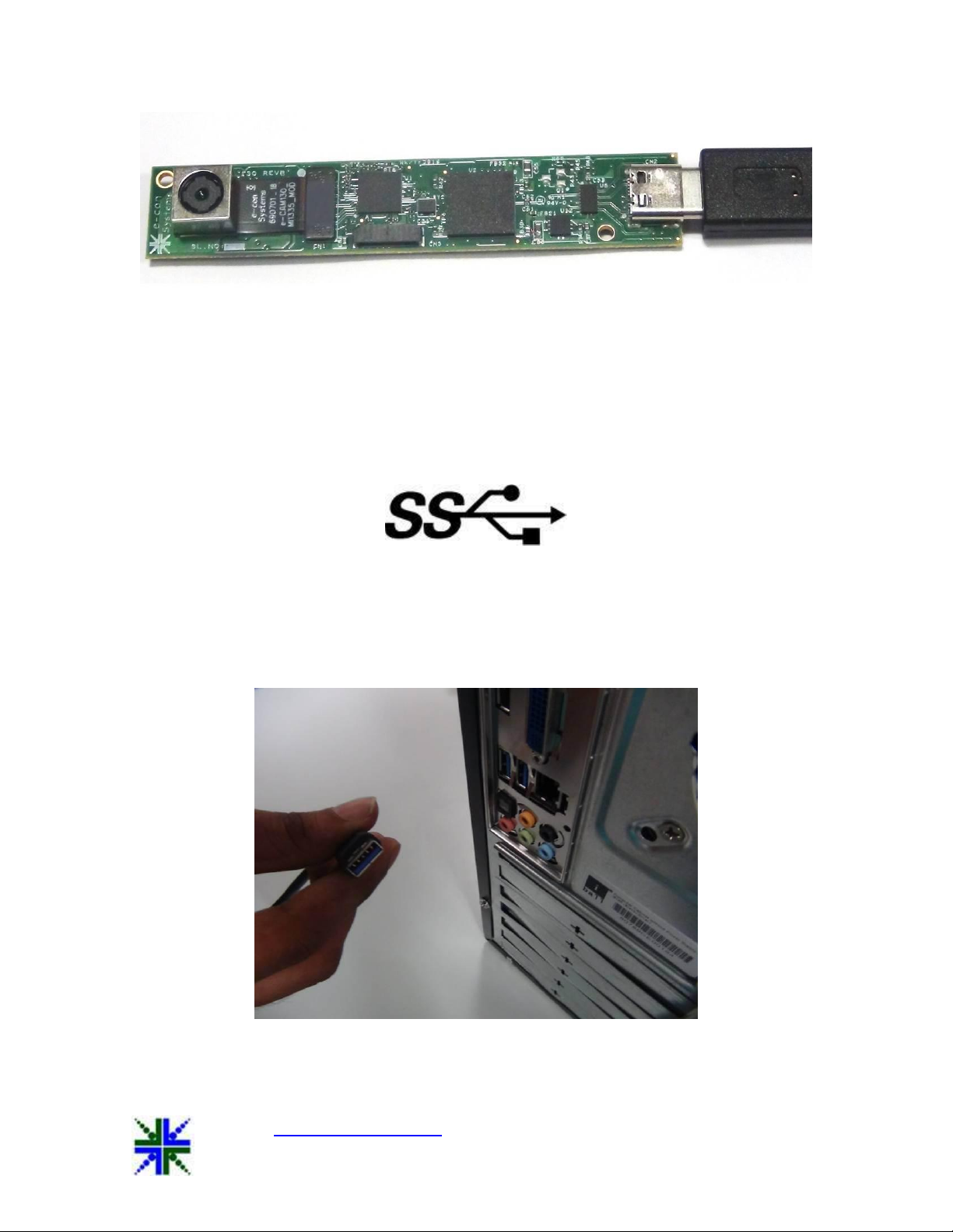
Figure 4: USB cable inserted in USB3.1 GEN_1 Type C connector
6.2.3 Connecting the board to Host
Identify a USB 3.1 GEN_1 port. The port which has the below logo is USB 3.1 GEN_1 Port.
Figure 5: SuperSpeed USB 3.1 GEN_1 Logo
The USB3.1 GEN_1 cable needs to be inserted to SuperSpeed USB3.1 GEN_1 port of PC or
Laptop.
Figure 6: USB3.1 GEN_1 Cable – Host Side
See3CAM_130 Getting Started Manual 24-Oct-2016
www.e-consystems.com | Subject to change without notice Page 8 of 9
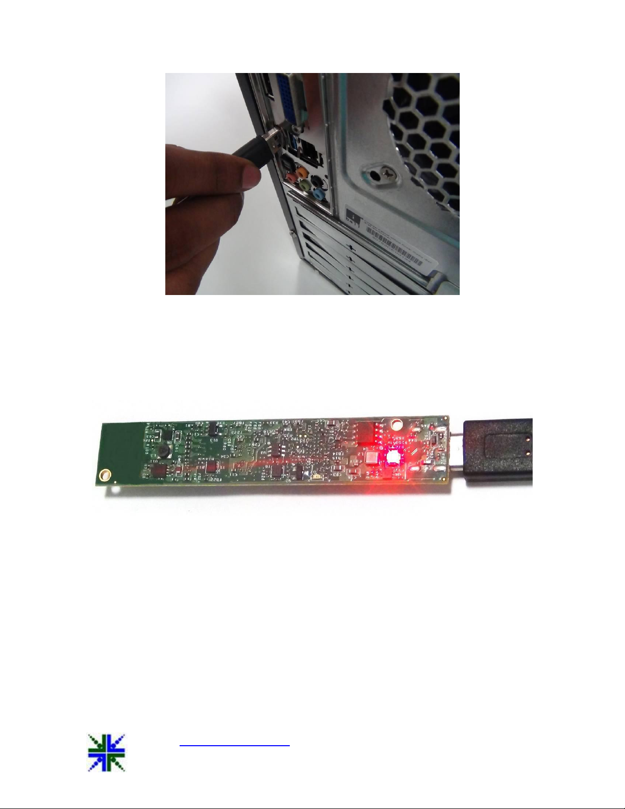
Figure 7: Connecting USB3.1 GEN_1 Cable to Superspeed Port
After the insertion of USB3.1 GEN_1 Cable with USB 3.1_GEN_1 / Type C connector on the
board and USB Host, the LED (D1) will glow in Red colour. This indicates that the board is
powered ON.
Figure 8: Status LED indicating Board Powered ON
After selecting the See3CAM_130 device in e-CAMView application the D2 LED glows in Green
colour. This indicates that the camera is in streaming condition.

See3CAM_130 Getting Started Manual 24-Oct-2016
www.e-consystems.com | Subject to change without notice Page 9 of 9
Figure 9: Status LED indicating Camera streaming
6.2.4 Ensuring the device connected to Host properly
After the insertion of board to Host, you can confirm that See3CAM_130 is properly connected to
Host from Imaging Devices.
Go to Control Panel System and Security Device Manager Imaging Devices
See3CAM_130
Figure 10: Imaging Devices showing See3CAM_130 connected to Host
7 Conclusion
This document describes How to connect See3CAM_130 board to USB3.1 GEN_1 Host and how
to get it working.
Other manuals for See3CAM 130
2
Table of contents
Popular Machine Vision System manuals by other brands

PhaseOne
PhaseOne RP1 1600 installation manual

Cognex
Cognex In-Sight 8405 manual

Premio
Premio VCO-6000-CFL Series user manual

Ark Vision Systems
Ark Vision Systems AVS-QuadUnit FHD instruction manual

National Instruments
National Instruments NI EVS-1463 Getting started

Panasonic
Panasonic Micro-Imagechecker AX40 user manual


