E-FLITE Horizon Hobby UMX Voodoo P-51D User manual
UMX™P-51D
Voodoo
Instruction Manual
Bedienungsanleitung
Manuel d’utilisation
Manuale di Istruzioni
EFLU4350
Scan the QR code and select the Manuals and Support quick links from
the product page for the most up-to-date manual information.
Scannen Sie den QR-Code und wählen Sie auf der Produktseite
die Quicklinks Handbücher und Unterstützung, um die aktuellsten
Informationen zu Handbücher.
Scannez le code QR et sélectionnez les liens rapides Manuals and Support
sur la page du produit pour obtenir les informations les plus récentes
sur le manuel.
Scannerizzare il codice QR e selezionare i Link veloci Manuali e Supporto
dalla pagina del prodotto per le informazioni manuali più aggiornate.

UMX P-51D Voodoo BNF Basic
2
EN
Safety Precautions and Warnings
As the user of this product, you are solely responsible for operating in a manner that does not endanger yourself and oth-
ers or result in damage to the product or the property of others.
• Always keep a safe distance in all directions around
your model to avoid collisions or injury.This model is
controlled by a radio signal subject to interference from
many sources outside your control. Interference can
cause momentary loss of control.
• Always operate your model in open spaces away from
full-size vehicles, traffic and people.
• Always carefully follow the directions and warnings
for this and any optional support equipment (chargers,
rechargeable battery packs, etc.).
• Always keep all chemicals, small parts and anything
electrical out of the reach of children.
• Always avoid water exposure to all equipment not
specifically designed and protected for this purpose.
Moisture causes damage to electronics.
• Never place any portion of the model in your mouth as it
could cause serious injury or even death.
• Never operate your model with low transmitter batteries.
• Always keep aircraft in sight and under control.
• Always use fully charged batteries.
• Always keep transmitter powered on while aircraft is
powered.
• Always remove batteries before disassembly.
• Always keep moving parts clean.
• Always keep parts dry.
• Always let parts cool after use before touching.
• Always remove batteries after use.
• Always ensure failsafe is properly set before flying.
• Never operate aircraft with damaged wiring.
• Never touch moving parts.
WARNING: Read the ENTIRE instruction manual to become familiar with the features of the product before
operating. Failure to operate the product correctly can result in damage to the product, personal property and
cause serious injury.
This is a sophisticated hobby product. It must be operated with caution and common sense and requires some basic
mechanical ability. Failure to operate this Product in a safe and responsible manner could result in injury or damage to the
product or other property. This product is not intended for use by children without direct adult supervision. Do not use with
incompatible components or alter this product in any way outside of the instructions provided by Horizon Hobby, LLC. This
manual contains instructions for safety, operation and maintenance. It is essential to read and follow all the instructions
and warnings in the manual, prior to assembly, setup or use, in order to operate correctly and avoid damage or serious
injury.
WARNING AGAINST COUNTERFEIT PRODUCTS: If you ever need to replace your Spektrum receiver found in a
Horizon Hobby product, always purchase from Horizon Hobby, LLC or a Horizon Hobby authorized dealer to
ensure authentic high-quality Spektrum product. Horizon Hobby, LLC disclaims all support and warranty with regards,
but not limited to, compatibility and performance of counterfeit products or products claiming compatibility with DSM
or Spektrum technology.
NOTICE
All instructions, warranties and other collateral documents are subject to change at the sole discretion of Horizon
Hobby, LLC. For up-to-date product literature, visit horizonhobby.com or towerhobbies.com and click on the support or
resources tab for this product.
MEANING OF SPECIAL LANGUAGE
The following terms are used throughout the product literature to indicate various levels of potential harm when
operating this product:
WARNING: Procedures, which if not properly followed, create the probability of property damage, collateral damage,
and serious injury OR create a high probability of superficial injury.
CAUTION: Procedures, which if not properly followed, create the probability of physical property damage AND a
possibility of serious injury.
NOTICE: Procedures, which if not properly followed, create a possibility of physical property damage AND little or no
possibility of injury.
Age Recommendation: Not for children under 14 years. This is not a toy.

3
EN
17.3 in (439.5mm)
19.4 in (493mm)
Included / Recommended Equipment
Motor:
Brushless Outrunner, 2150Kv, 12-Pole
(SPMXAM1208B)
Installed
Servo:
(4) 2.3-Gram Long-Throw Linear Servo
(SPMSA2030LO)
Installed
Receiver:
Spektrum™AS3X/SAFE Receiver (SPMA3190) Installed
Recommended Battery:
Spektrum 300mAh 3S 11.1V 30C; JST-RCY Li-Po
(SPMX3003SJ30)
Required
Recommended Battery Charger:
S155 (SPMXC2050) WITH IC3 to JST-RCY adapter
(SPMXCA310)
Required
Recommended Transmitter:
Full-Range 2.4GHz with Spektrum™DSM2®/
DSMX®technology with programmable
mixing and adjustable dual rates
Required
General Binding Tips and Failsafe BNF
• The included receiver has been specifically programmed
for operation of this aircraft. Refer to the receiver manual
for correct setup if the receiver is replaced.
• Keep away from large metal objects while binding.
• Do not point the transmitter’s antenna directly at the
receiver while binding.
• The orange LED on the receiver will flash rapidly when
the receiver enters bind mode.
• Once bound, the receiver will retain its bind settings for
that transmitter until you re-bind.
• If the receiver loses transmitter communication, the
failsafe will activate. Failsafe moves the throttle channel
to low throttle. Pitch and roll channels move to actively
stabilize the aircraft in a descending turn.
• If problems occur, refer to the troubleshooting guide or if
needed, contact the appropriate Horizon Product Support
office.
Without Battery: 92g (3.2 oz)
With 3S 300mAh Battery: 112g (4 oz)
Table of Contents
Low Voltage Cutoff (LVC) ........................................4
Transmitter Setup ..................................................4
Transmitter and Receiver Binding...........................4
Smart Technology Telemetry ..................................5
SAFE®Select Technology.......................................5
ESC/Receiver Arming and Battery Installation.........6
Center of Gravity (CG) ............................................6
Control Direction Test.............................................7
AS3X Control Response Tests.................................8
Control Centering ..................................................8
Landing Gear Removal...........................................9
Control Horn Settings...........................................10
Flying Tips and Repairs........................................10
Hand Launching...................................................10
Post Flight Checklist ............................................11
Power Components Service .................................11
AS3X®System Trouble Shooting Guide.................12
Troubleshooting Guide .........................................12
Troubleshooting Guide .........................................13
Replacement Parts...............................................14
Recommended Parts............................................14
Optional Parts and Accessories ............................14
Important Federal Aviation Administration (FAA)
Information..........................................................15
AMA National Model Aircraft Safety Code.............15
Limited Warranty .................................................15
Contact Information .............................................16
FCC Information...................................................17
IC Information......................................................17
Compliance Information for the European Union...17
EN
UMX P-51D Voodoo BNF Basic
4
When a Li-Po battery is discharged below 3V per cell, it
will not hold a charge. The aircraft’s ESC protects the flight
battery from over-discharge using Low Voltage Cutoff
(LVC). Once the battery discharges to 3V per cell, the
LVC will reduce the power to the motor in order to leave
adequate power to the receiver and servos to land the
airplane.
When the motor power decreases, land the aircraft im-
mediately and replace or recharge the flight battery.
Always disconnect and remove the Li-Po battery from
the aircraft after each flight. Charge your Li-Po battery to
about half capacity before storage. Make sure the battery
charge does not fall below 3V per cell. Failure to unplug a
connected battery will result in trickle discharge.
For your first flights, set your transmitter timer or a stop-
watch to 5 minutes. Adjust your timer for longer or shorter
flights once you have flown the model.
NOTICE: Repeated flying to LVC will damage the battery.
Low Voltage Cutoff (LVC)
Binding is the process of programming the receiver to recognize the GUID (Globally Unique Identifier) code of a single
specific transmitter. You need to ‘bind’ your chosen Spektrum™DSM2/DSMX technology equipped aircraft transmitter to
the receiver for proper operation.
Any full range Spektrum DSM2/DSMX transmitter can bind to the DSM2/DSMX receiver.
Transmitter and Receiver Binding
Binding Procedure
1. Refer to your transmitter’s unique instructions for binding to a receiver (location of transmitter’s Bind control).
2. Make sure the flight battery is disconnected from the aircraft.
3. Power off your transmitter.
4. Place the aircraft on a level surface away from wind.
5. Connect the flight battery in the aircraft. The receiver LED will begin to flash rapidly (typically after 5 seconds).
6. Make sure the transmitter controls are neutral and the throttle and throttle trim are in low position.
7. Put your transmitter into bind mode. Refer to your transmitter’s manual for binding button or switch
instructions.
8. After 5 to 10 seconds, the receiver status LED will turn solid, indicating that the receiver is bound to the
transmitter. If the LED does not turn solid, refer to the Troubleshooting Guide at the back of the manual.
For subsequent flights, power ON the transmitter for 5 seconds before connecting the flight battery.
IMPORTANT: After you set up your model, always rebind
the transmitter and receiver to set the desired failsafe
positions.
If your transmitter allows it, enable the throttle cut feature.
Always engage throttle cut before approaching the aircraft.
Dual Rates
Low rate is recommended for the initial ights.
NOTICE: To ensure AS3X®technology functions properly,
do not lower rate values below 50%.
NOTICE: If oscillation occurs at high speed, refer to the
Troubleshooting Guide for more information.
Exponential
After your initial flights, you may adjust the exponential
value to better suit your flying style.
Computerized Transmitter Setup
DX series, NX series, iX series
Start all transmitter programming with a blank ACRO
model (do a model reset), then name the model.
Reversing All Normal
Dual Rates HIGH 100%
LOW 70%
Expo 10% on aileron, elevator
and rudder
Servo Travel 100%
Timer 5 minutes
Set Throttle cut to -100%
Transmitter Setup

EN
5
SAFE®Select Technology
Disabling and Enabling SAFE Select
By default, the SAFE Select function of your UMX aircraft is
enabled and assigned to the Gear channel switch (channel
5). If you do not wish to have access to SAFE Select while
flying, you can choose to disable SAFE Select functionality.
AS3X will still be active when SAFE Select is disabled.
IMPORTANT: Before attempting to disable or enable SAFE
Select, ensure the aileron, elevator, rudder, throttle and
gear channels are all on high rate with the travel set to
100%. Turn throttle hold OFF if it is programmed in the
transmitter.
CAUTION: Keep all body parts clear of the
propeller, and keep the aircraft securely
restrained in case of accidental throttle
activation.
1. Power on the transmitter.
2. Power on the aircraft.
3. Hold both transmitter sticks to the inside bottom
corners and toggle the Gear switch 5 times
(1 toggle = full up and down). The control surfaces of
the aircraft will move, indicating SAFE Select has been
enabled or disabled.
Repeat the process again to re-enable or disable SAFE
Select.
DXe, and DXS Transmitters
Switch A is the FMODE switch on the these transmitters,
and the switch needs to be toggled between position 0
and 2 when disabling/enabling SAFE Select.
100%
x 5
100%
Mode 1 and 2 Transmitters
The P-51D Voodoo has two flight modes controlled by
Channel 5, SAFE and AS3X. Switch A is the Spektrum default
for channel 5. Position 0 is SAFE, Position 1 is AS3X only.
When flying in SAFE mode, the aircraft will return to level
flight any time the aileron and elevator controls are at
neutral. Applying aileron or elevator control will cause
the airplane to bank, climb or dive. The amount the stick
is moved will determine the attitude the airplane flies.
Holding full control will push the aircraft to the pre-
determined bank and pitch limits, but it will not go past
those angles.
When flying in SAFE mode, it is normal to hold the control
stick deflected with moderate aileron input when flying
through a turn. To fly smoothly with SAFE, avoid making
frequent control changes and don’t attempt to correct for
minor deviations. Holding deliberate control inputs will
command the aircraft to fly at a specific angle, and the
model will make all corrections to maintain that flight
attitude.
Return the elevator and aileron controls to neutral before
switching from SAFE mode to AS3X mode. If you do not
neutralize controls when switching into AS3X mode, the
control inputs used for SAFE mode will be excessive for
AS3X mode and the aircraft will react immediately.
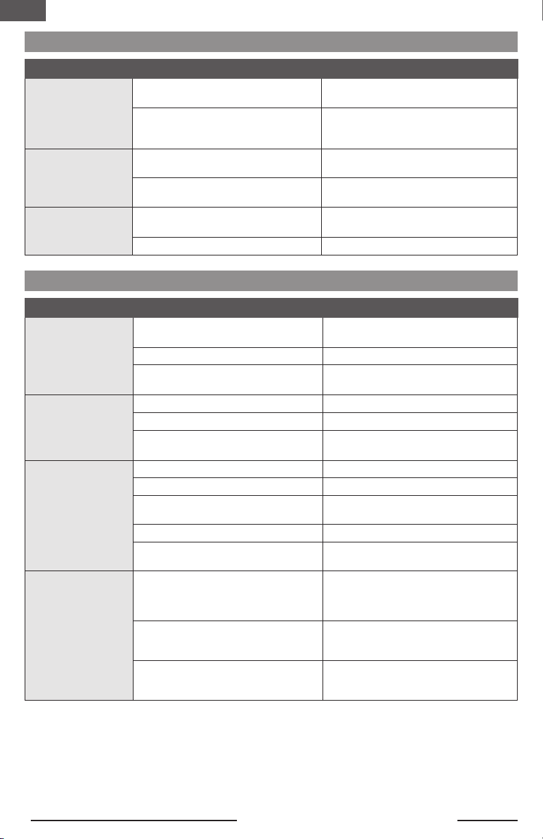
SAFE Select AS3X
Control Input
Control stick is
neutralized Aircraft will self level Aircraft will continue to fly at its
present attitude
Holding a small
amount of control
Aircraft will bank or pitch to a moderate angle and
maintain the attitude
Aircraft will continue to pitch or
roll slowly
Holding full control Aircraft will bank or pitch to the predetermined
limits and maintain the attitude
Aircraft will continue to roll or pitch
rapidly
Differences between SAFE and AS3X modes
This section is generally accurate but does not take into account flight speed, battery charge status, and other limiting factors.
Smart Technology Telemetry
This aircraft includes Spektrum Smart Technology in the
receiver, which can provide telemetry information like
battery voltage. To take advantage of Smart Technology,
you will need a compatible transmitter. A firmware update
for your transmitter may be required.
To View Smart Telemetry:
1. Begin with the transmitter bound to the receiver
2. Power on the transmitter.
3. Power on the aircraft.
4. The Smart Logo appears under the battery logo on
the home page. A signal bar appears in the top left
corner of the screen.
5. Scroll past the servo monitor to view Smart
technology screens.
For more information about compatible transmitters,
firmware updates, and how to use the Smart Technology
on your transmitter, visit www.SpektrumRC.com.
EN
UMX P-51D Voodoo BNF Basic
6
4
1-2-3-4-5 Sec.
1
2
3
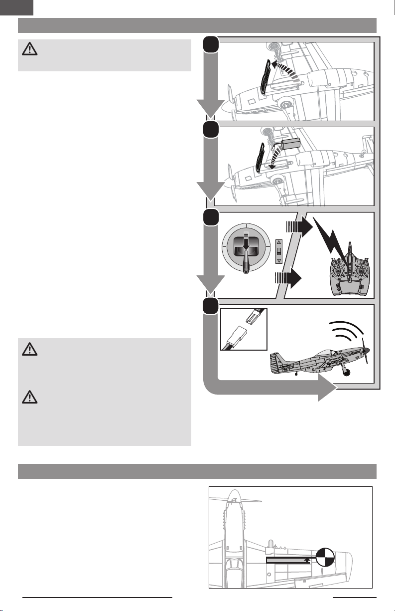
ESC/Receiver Arming and Battery Installation
8mm
The CG location is 8mm forward of the panel line shown in
the illustration. This CG location has been determined with
the recommended battery. Check the CG with the model
inverted. Adjust the battery forward or aft so the model
balances level at the recommended point.
CAUTION: Always keep hands away from the
propeller. When armed, the motor will turn the
propeller in response to any throttle movement.
Arming the ESC/receiver also occurs after binding as
previously described, but subsequent connection of a flight
battery requires the following steps.
AS3X
The AS3X®system will not activate until the throttle stick
or trim is increased above 25% for the first time. Once
active, the control surfaces may move rapidly and noisily
on the aircraft. This is normal. AS3X technology will remain
active until the battery is disconnected.
1. Open the battery hatch.
2. Attach the battery to the hook and loop strip so the
battery is centered in the battery cavity.
3. Lower the throttle and power on your transmitter. En-
able throttle cut switch.
4. Connect the battery to the ESC, noting proper polarity.
Keep the plane immobile and away from wind for 5
seconds to allow the AS3X system to initialize. A series
of tones and a continuous LED (LED may be difficult to
see as it is located inside of aircraft.) indicates a suc-
cessful connection.
A solid blue LED indicates that the aircraft is in SAFE
flight mode and a solid RED LED indicates that the
aircraft is in AS3X flight mode. When the aircraft is in
SAFE the servos will move without increasing throttle
above 25% throttle
2S batteries with a PH plug require an adapter lead.
(SPMXCA327).
CAUTION: Always disconnect the Li-Po battery
from the ESC when not flying to eliminate power
supplied to the motor. The ESC does not have an
arming switch and will respond to any transmitter input
when a signal is present.
CAUTION: Always disconnect the Li-Po battery
from the ESC when not flying to avoid
over-discharging the battery. Batteries discharged to a
voltage lower than the lowest approved voltage may
become damaged, resulting in loss of performance and
potential fire when batteries are charged.
Center of Gravity (CG)

EN
7
Switch on the transmitter, enable throttle cut and connect the battery.. Use the transmitter to operate the aileron, elevator
and rudder controls. View the aircraft from the rear when checking the control directions.
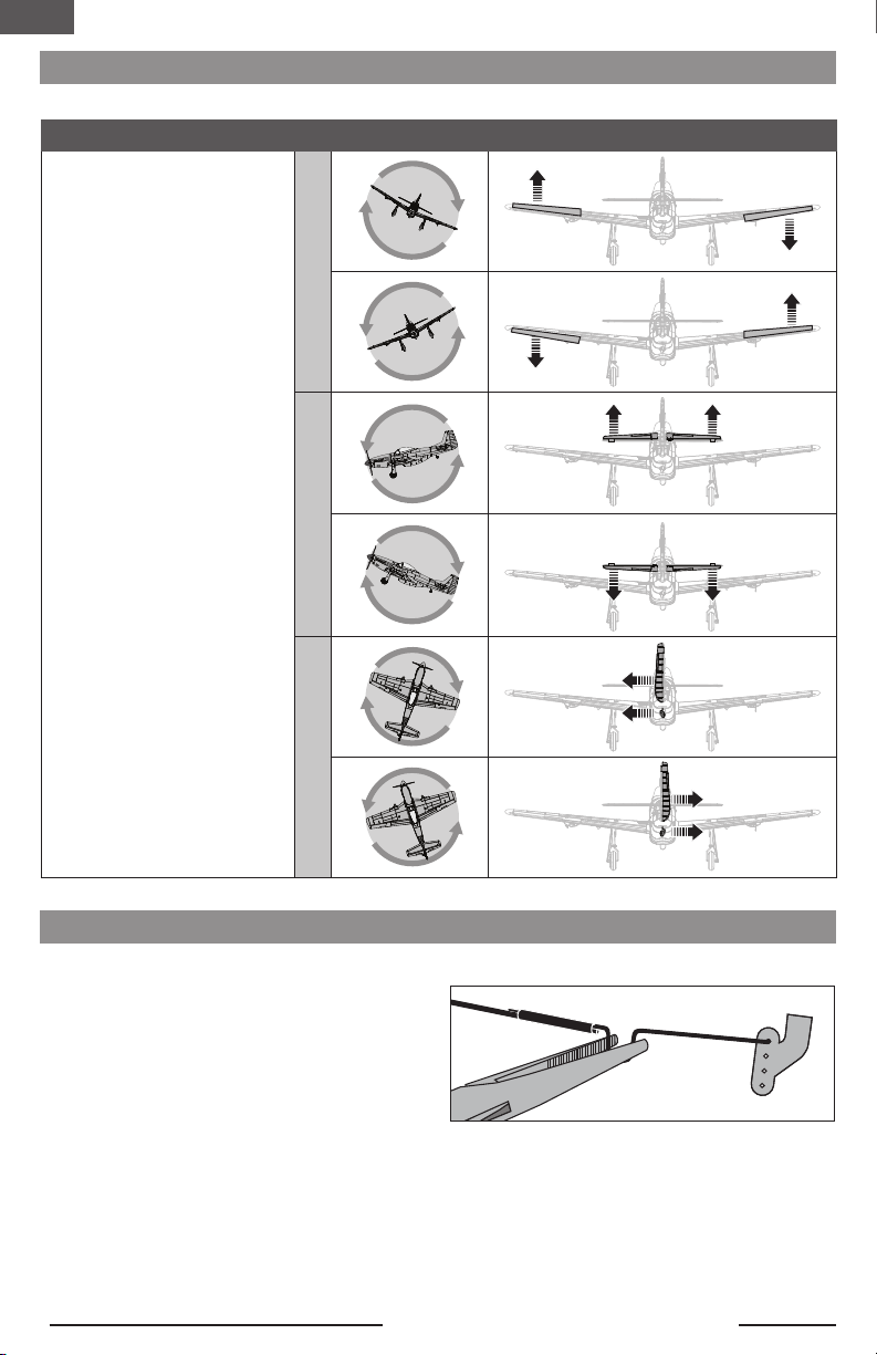
Control Direction Test
Transmitter
command Control Surface Response
Elevators
1. Pull the elevator stick back.
The elevator should move up,
which will cause the aircraft to
pitch up.
2. Push the elevator stick forward.
The elevator should move down,
which will cause the aircraft to
pitch down.
Ailerons
1. Move the aileron stick to the
left. The left aileron should
move up and the right aileron
down, which will cause the
aircraft to bank left.
2. Move the aileron stick to the
right. The right aileron should
move up and the left aileron
down, which will cause the
aircraft to bank right.
Rudder
1. Move the rudder stick to the
left. The rudder should move to
the left, which will cause the
aircraft to yaw left.
2. Move the rudder stick to the
right. The rudder should move
to the right, which will cause
the aircraft to yaw right.
ElevatorAileronRudder
EN
UMX P-51D Voodoo BNF Basic
8
1. Advance the throttle above 25%
to activate the AS3X system.
2. Fully lower the throttle and
enable throttle cut.
3. Move the entire aircraft as
shown and ensure the control
surfaces move in the direction
indicated in the graphic. If the
control surfaces do not respond
as shown, do not fly the aircraft.
Refer to the receiver manual for
more information.
Once the AS3X system is active,
control surfaces may move rapidly.
This is normal. AS3X is active until
the battery is disconnected.
AS3X Control Response Tests
This test ensures that the AS3X®control system is functioning properly.
Before the rst ights, or in the event of an accident,
make sure the ight control surfaces are centered.
Adjust the linkages mechanically if the control surfaces
are not centered. Use of the transmitter sub-trims may not
correctly center the aircraft control surfaces due to the
mechanical limits of linear servos.
1. Make sure the control surfaces are neutral when
the transmitter controls and trims are centered. The
transmitter sub-trim must always be set to zero.
2. When needed, use a pair of pliers to carefully bend the
metal linkage (see illustration).
3. Make the U-shape narrower to make the linkage
shorter. Make the U-shape wider to make the linkage
longer.
Centering Controls After First Flights
For best performance with AS3X, it is important that
excessive trim is not used. If the aircraft requires exces-
sive transmitter trim (4 or more clicks of trim per channel),
return the transmitter trim to zero and adjust the linkages
mechanically so that the control surfaces are in the flight
trimmed position.
Control Centering

EN
9
Landing Gear Removal
Main Gear
1. Carefully unclip the landing gear cover from the strut,
then pull it down and away from the wing.
2. Carefully rotate each strut until it snaps away from the
gear plate.
NOTICE: DO NOT damage the leading edge of the wing
when removing the landing gear.
3. Pull the landing gear strut out of the mounting plate
hole.
When needed, assemble in reverse order.
Tail Wheel
1. Pull the tail wheel assembly out of the plastic tail
wheel mount on the bottom of the fuselage.
When needed, assemble in reverse order.
EN
UMX P-51D Voodoo BNF Basic
10
Flying Tips and Repairs
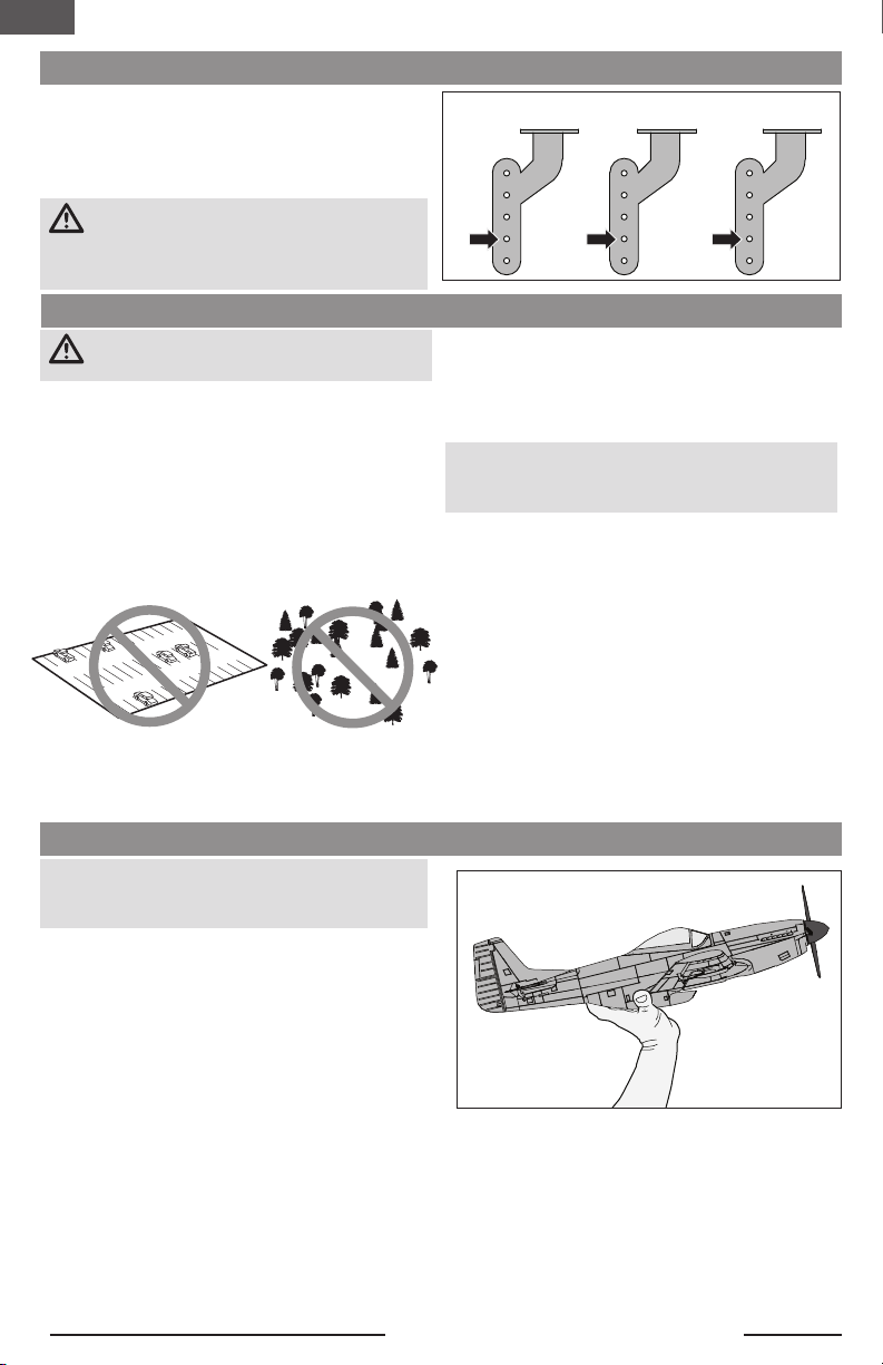
Control Horn Settings
The illustration shows the factory settings for the control
horns. Fly the aircraft at factory settings before making
changes.
After flying, you may choose to adjust the linkage positions
for the desired control response.
CAUTION: When these are incorrectly connected
for the pilot’s skill level, unexpected aircraft
response to controls can result. This can cause damage
to the aircraft and personal injury.
Aileron Elevator Rudder
WARNING: Always engage throttle cut before
approaching the aircraft.
Range Check your Radio System
Range check the radio system with the aircraft. Refer to
your specific transmitter instruction manual for range test
information.
Flying
We recommend flying your aircraftoutside in no greater
than moderate winds or inside in a large gymnasium.
Always avoid flying near houses, trees, wires and buildings.
You should also be careful to avoid flying in areas where
there are many people, such as busy parks, schoolyards
or soccer fields. Consult local laws and ordinances before
choosing a location to fly your aircraft.
Takeoff
Place the aircraft in position for takeoff (facing into the
wind if flying outdoors). Set dual rates to low position and
gradually increase the throttle to ¾ to full and steer with
the rudder. Pull back gently on the elevator and climb to
check trim. Once the trim is adjusted, begin exploring the
flight envelope of the aircraft.
Landing
Always land into the wind. During the flare, keep the wings
level and the aircraft pointed into the wind. Slowly lower
the throttle while easing back on the elevator to bring the
aircraft gently down on all three wheels.
NOTICE: Always fully lower the throttle at touch down
when landing the aircraft to prevent damage to the
propeller and motor.
Failure to lower the throttle stick and trim to the lowest
possible positions during a crash could result in damage to
the ESC in the receiver unit.
Over-Current Protection (OCP)
The aircraft is equipped with over-current protection.
OCP protects the ESC from overheating and stops the
motors when the transmitter throttle is set too high and
the propeller cannot turn. OCP will only activate when the
throttle is positioned just above 1/2 throttle. After the ESC
stops the motor, fully lower the throttle to re-arm the ESC.
Repairs
Crash damage is not covered under warranty.
Repair this aircraft using foam-compatible CA glue or clear
tape. Only use foam-compatible CA glue as other types of
glue can damage the foam. When parts are not repairable,
see the Replacement Parts List for ordering by item number.
Hand Launching
NOTICE: Hand Launching in AS3X mode is not
recommended as it may result in a crash. Always hand
launch in SAFE Mode.
• We recommend flying without landing gear when hand
launching.
• Always hand launch in SAFE mode, into the wind at
100% power, in high rates.
When hand launching in SAFE mode, the control unit
will immediately sense the force of the launch and will
automatically enable the Hand Launch Assist feature.
When this feature is active, the control unit will add up
elevator automatically so the aircraft climbs at a higher
angle for a few seconds. It will return to standard SAFE
mode shortly after launch.
Grip
We recommend holding the aircraft just behind the wings,
as shown.
Follow Through
Use an overhand throw and launch with wings level and
the nose of the model slightly upwards. Follow through
with your hand launch by pointing your fingers at the
airplane after the throw. Avoid an arcing throw which can
pull the nose down at release.
EN
11
Post Flight Checklist
1. Disconnect the flight battery from the ESC
(Required for safety and battery life).
2. Power OFF the transmitter.
3. Remove the flight battery from the aircraft.
4. Store the flight battery apart from the aircraft
and monitor the battery charge.
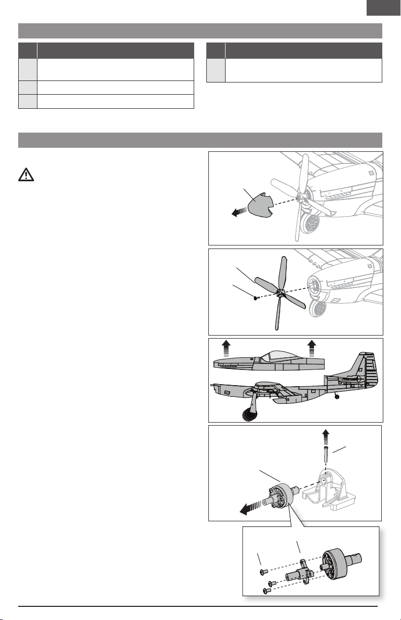
Power Components Service
Disassembly
CAUTION: DO NOT handle the propeller
while the flight battery is connected to the ESC. Personal
injury could result.
Propeller
1. Gently grasp the spinner (A) taking care not to crush
it, and pull while rocking the spinner back and forth to
break the adhesive.
The propeller and spinner are glued
together, glue residue will need to be cleaned
from the spinner or propeller when these parts are
used again.
2. Carefully remove the 2 x 6mm self-tapping screw (B)
using a Phillips #1 screwdriver.
3. Carefully remove the propeller (C) from the motor shaft.
Motor
1. Carefully cut the tape and/or decals on the side of the
fuselage to remove the top of the fuselage.
2. Disconnect the motor wire connector from the ESC/
receiver connector.
3. Remove the M2 x 10 machine screw (D) using a
Phillips #1 screwdriver.
4. Remove the motor (E) from the motor mount.
5. Remove 3 M1.5 x 3 machine screws (F) using a Phillips
#0 screwdriver.
6. Remove the propeller adapter (G)from the motor. The
motor magnet may attract screws to the motor.
Assembly
Assemble in reverse order.
• Connect the motor wire connector to the ESC/receiver.
• The two dimples in the propeller hub must be facing
forward for correct propeller operation.
• Attach the spinner to the propeller using foam compat-
ible CA (cyanoacrylate adhesive).
• Ensure the propeller adapter and motor mount are fully
connected to the motor.
• Assemble the fuselage using clear tape.
A
B
C
E
D
G
F
EN
UMX P-51D Voodoo BNF Basic
12
Problem Possible Cause Solution
Control surfaces not at
neutral position when
transmitter controls are
at neutral
Control surfaces may not have been
mechanically centered from factory Center control surfaces mechanically by
adjusting the U-bends on control linkages
Aircraft was moved after the flight battery
was connected and before sensors
initialized
Disconnect and reconnect the flight battery
while keeping the aircraft still for 5 seconds
Model flies inconsis-
tently from flight to
flight
Aircraft was not kept immobile for 5
seconds after battery was plugged in Keep the aircraft immobile for 5 seconds after
plugging in the battery
Trims are moved too far from neutral
position Neutralize trims and mechanically adjust
linkages to center control surfaces
Controls oscillate in
flight, (model rapidly
jumps or moves)
Propeller is unbalanced, causing excessive
vibration
Remove propeller and rebalance or replace it
if damaged
Propeller screw is loose, causing vibration Tighten the propeller screw
Problem Possible Cause Solution
Aircraft will not respond
to throttle but responds
to other controls
Throttle stick and/or throttle trim too high Reset controls with throttle stick and throttle
trim at lowest setting
Throttle channel is reversed Reverse throttle channel on transmitter
Motor disconnected from receiver Open fuselage and make sure motor is
connected to the receiver
Extra propeller noise or
extra vibration
Damaged propeller, spinner or motor Replace damaged parts
Propeller screw is loose Tighten the propeller screw
Propeller is out of balance Remove and balance propeller, or replace
with a balanced propeller
Reduced flight time or
aircraft underpowered
Flight battery charge is low Completely recharge flight battery
Propeller installed backwards Install propeller with numbers facing forward
Flight battery damaged Replace flight battery and follow flight battery
instructions
Flight conditions may be too cold Make sure battery is warm before use
Battery capacity too low for flight conditions Replace battery or use a larger capacity
battery
LED on receiver flashes
and aircraft will not bind
to transmitter (during
binding)
Transmitter too near aircraft during binding
process
Power off transmitter, move transmitter a
larger distance from aircraft, disconnect and
reconnect flight battery to aircraft and follow
binding instructions
Bind switch or button not held long enough
during bind process
Power off transmitter and repeat bind pro-
cess. Hold transmitter bind button or switch
until receiver is bound
Aircraft or transmitter is too close to large
metal object, wireless source or another
transmitter
Move aircraft and transmitter to another
location and attempt binding again
Troubleshooting Guide
AS3X®System Trouble Shooting Guide

EN
13
Problem Possible Cause Solution
LED on receiver flashes
rapidly and aircraft will
not respond to transmit-
ter (after binding)
Less than a 5-second wait between first
powering on transmitter and connecting
flight battery to aircraft
Leaving transmitter on, disconnect and
reconnect flight battery to aircraft
Aircraft bound to different model memory
(ModelMatch™radios only)
Select correct model memory on transmitter
and disconnect and reconnect flight battery
to aircraft
Flight battery/transmitter battery charge is
too low Replace/recharge batteries
Transmitter may have been bound to a
different model (or with a different DSM
Protocol)
Select the right transmitter or bind to the
new one
Aircraft or transmitter is too close to large
metal object, wireless source or another
transmitter
Move aircraft and transmitter to another
location and attempt linking again
Control surface does
not move
Control surface, control horn, linkage or
servo damage Replace or repair damaged parts and adjust
controls
Wire damaged or connections loose Do a check of wires and connections, con-
nect or replace as needed
Flight battery charge is low Fully recharge flight battery
Control linkage does not move freely Make sure control linkage moves freely
Controls reversed Transmitter settings reversed Adjust controls on transmitter appropriately
Motor loses power Damage to motor or power components Do a check of motor and power components
for damage (replace as needed)
Motor power quickly
decreases and in-
creases then motor
loses power
Battery power is down to the point of
receiver/ESC Low Voltage Cutoff (LVC) Recharge flight battery or replace battery that
is no longer performing
Motor/ESC is not armed
after landing
Over Current Protection (OCP) stops the
motor when the transmitter throttle is set
high and the propeller cannot turn
Fully lower throttle and throttle trim to
arm ESC
Servo locks or freezes
at full travel Travel adjust value is set above 100%,
overdriving the servo
Set Travel adjust to 100% or less and/or set
sub-trims to Zero and adjust linkages
mechanically
Troubleshooting Guide
EN
UMX P-51D Voodoo BNF Basic
14
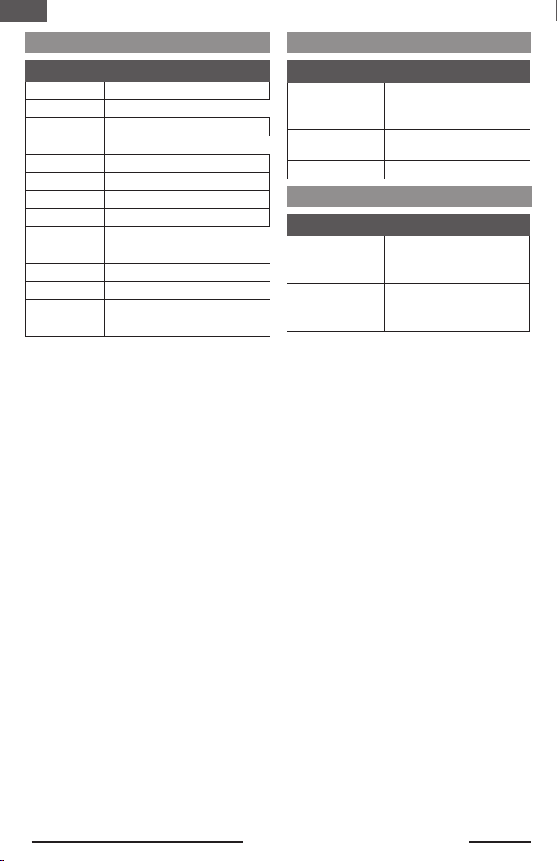
Optional Parts and Accessories
Part # Description
SPMR6775 NX6 6 Ch Transmitter Only
SPMR8105 DX8e 8 Ch DSMX Transmitter
Only
SPMXC2020 Smart S1200 G2 AC Charger;
1x200
SPMX3002S30 300mAh 2S 7.4V 30C LiPo; PH
Replacement Parts
Part # Description
EFLU3306 Motor Mount: UMX P-51
EFLU3308 Pushrod Set: UMX P-51
EFLU4067 Propeller Adapter
EFLU4301 Wing: UMX P-51 Voodoo
EFLU4302 Fuselage w/Acc: UMX P-51 Voodoo
EFLU4303 Spinner: UMX P-51 Voodoo
EFLU4304 Tail Set: UMX P-51 Voodoo
EFLU4305 Landing Gear: UMX P-51 Voodoo
EFLU4307 Decal Sheet: UMX P-51 Voodoo
EFLU4309 Battery Door: UMX P-51 Voodoo
EFLUP45404 Propeller: 4.5 x 4.0
SPMA3190 Receiver/ESC: UMX P-51 Voodoo
SPMSA2030LO 2.3g Long-Throw Offset Linear Servo
SPMXAM1208B Brushless Motor: UMX P-51 Voodoo
Part # Description
SPMR6655 DX6e 6 Channel Transmitter
Only
SPMX3003SJ30 300mAh 3S 11.1V 30C; JST
SPMXC2050 Smart S155 G2 AC 1x55W
Charger
SPMXCA310 Adapter: IC3 Battery/JST Device
Recommended Parts

EN
15
AMA National Model Aircraft Safety Code
Effective January 1, 2018
A model aircraft is a non-human-carrying device capable of sustained flight within visual line of sight of the pilot or spotter(s). It
may not exceed limitations of this code and is intended exclusively for sport, recreation, education and/or competition. All model
flights must be conducted in accordance with this safety code and related AMA guidelines, any additional rules specific to the
flying site, as well as all applicable laws and regulations.
As an AMA member I agree:
• I will not fly a model aircraft in a careless or reckless
manner.
• I will not interfere with and will yield the right of way to all
human-carrying aircraftusing AMA’s See and Avoid Guid-
ance and a spotter when appropriate.
• I will not operate any model aircraft while I am under the
influence of alcohol or any drug that could adversely affect
my ability to safely control the model.
• I will avoid flying directly over unprotected people, moving
vehicles, and occupied structures.
• I will fly Free Flight (FF) and Control Line (CL) models in
compliance with AMA’s safety programming.
• I will maintain visual contact of an RC model aircraft without
enhancement other than corrective lenses prescribed to
me. When using an advanced flight system, such as an
autopilot, or flying First-Person View (FPV), I will comply
with AMA’s Advanced Flight System programming.
• I will only fly models weighing more than 55 pounds,
including fuel, if certified through AMA’s Large Model
Airplane Program.
• I will only fly a turbine-powered model aircraft in compli-
ance with AMA’s Gas Turbine Program.
• I will not fly a powered model outdoors closer than 25 feet
to any individual, except for myself or my helper(s) located
at the flightline, unless I am taking off and landing, or as
otherwise provided in AMA’s Competition Regulation.
• I will use an established safety line to separate all model
aircraft operations from spectators and bystanders.
Limited Warranty
What this Warranty Covers—Horizon Hobby, LLC, (Horizon)
warrants to the original purchaser that the product purchased
(the “Product”) will be free from defects in materials and
workmanship at the date of purchase.
What is Not Covered—This warranty is not transferable and
does not cover (i) cosmetic damage, (ii) damage due to acts of
God, accident, misuse, abuse, negligence, commercial use, or
due to improper use, installation, operation or maintenance, (iii)
modification of or to any part of the Product, (iv) attempted ser-
vice by anyone other than a Horizon Hobby authorized service
center, (v) Product not purchased from an authorized Horizon
dealer, (vi) Product not compliant with applicable technical
regulations, or (vii) use that violates any applicable laws, rules,
or regulations.
OTHER THAN THE EXPRESS WARRANTY ABOVE, HORIZON
MAKES NO OTHER WARRANTY OR REPRESENTATION, AND
HEREBY DISCLAIMS ANY AND ALL IMPLIED WARRANTIES,
INCLUDING, WITHOUT LIMITATION, THE IMPLIED WARRANTIES
OF NON-INFRINGEMENT, MERCHANTABILITY AND FITNESS
FOR A PARTICULAR PURPOSE. THE PURCHASER ACKNOWL-
EDGES THAT THEY ALONE HAVE DETERMINED THAT THE
PRODUCT WILL SUITABLY MEET THE REQUIREMENTS OF THE
PURCHASER’S INTENDED USE.
Purchaser’s Remedy—Horizon’s sole obligation and
purchaser’s sole and exclusive remedy shall be that Horizon
will, at its option, either (i) service, or (ii) replace, any Product
determined by Horizon to be defective. Horizon reserves the
right to inspect any and all Product(s) involved in a warranty
claim. Service or replacement decisions are at the sole discre-
tion of Horizon. Proof of purchase is required for all warranty
claims. SERVICE OR REPLACEMENT AS PROVIDED UNDER
THIS WARRANTY IS THE PURCHASER’S SOLE AND EXCLUSIVE
REMEDY.
Limitation of Liability—HORIZON SHALL NOT BE LIABLE
FOR SPECIAL, INDIRECT, INCIDENTAL OR CONSEQUENTIAL
DAMAGES, LOSS OF PROFITS OR PRODUCTION OR COM-
MERCIAL LOSS IN ANY WAY, REGARDLESS OF WHETHER
SUCH CLAIM IS BASED IN CONTRACT, WARRANTY, TORT,
Important Federal Aviation Administration (FAA) Information
Use the QR code below to learn more about the Recre-
ational UAS Safety Test (TRUST), as was introduced by
the 2018 FAA Reauthorization Bill. This free test is required
by the FAA for all recreational flyers in the United States. The
completed certificate must be presented upon request by any
FAA or law enforcement official.
If your model aircraft weighs more than .55lbs or 250 grams,
you are required by the FAA to register as a recreational flyer
and apply your registration number to the outside of your
aircraft. To learn more about registering with the FAA, use the
QR code below.

EN
UMX P-51D Voodoo BNF Basic
16
Contact Information
Country of
Purchase Horizon Hobby Contact Information Address
United States
of America
Horizon Service Center
(Repairs and Repair Requests)
servicecenter.horizonhobby.com/Request-
Form/
2904 Research Rd
Champaign, Illinois, 61822 USA
Horizon Product Support
(Product Technical Assistance)
productsupport@horizonhobby.com
877-504-0233
Sales websales@horizonhobby.com
800-338-4639
European Union Horizon Technischer Service service@horizonhobby.eu Hanskampring 9
D 22885 Barsbüttel, Germany
Sales: Horizon Hobby GmbH +49 (0) 4121 2655 100
NEGLIGENCE, STRICT LIABILITY OR ANY OTHER THEORY OF
LIABILITY, EVEN IF HORIZON HAS BEEN ADVISED OF THE
POSSIBILITY OF SUCH DAMAGES. Further, in no event shall the
liability of Horizon exceed the individual price of the Product on
which liability is asserted. As Horizon has no control over use,
setup, final assembly, modification or misuse, no liability shall
be assumed nor accepted for any resulting damage or injury.
By the act of use, setup or assembly, the user accepts all re-
sulting liability. If you as the purchaser or user are not prepared
to accept the liability associated with the use of the Product,
purchaser is advised to return the Product immediately in new
and unused condition to the place of purchase.
Law—These terms are governed by Illinois law (without
regard to conflict of law principals). This warranty gives you
specific legal rights, and you may also have other rights which
vary from state to state. Horizon reserves the right to change or
modify this warranty at any time without notice.
WARRANTY SERVICES
Questions, Assistance, and Services—Your local hobby
store and/or place of purchase cannot provide warranty sup-
port or service. Once assembly, setup or use of the Product
has been started, you must contact your local distributor or
Horizon directly. This will enable Horizon to better answer your
questions and service you in the event that you may need
any assistance. For questions or assistance, please visit our
website at www.horizonhobby.com, submit a Product Support
Inquiry, or call the toll free telephone number referenced in the
Warranty and Service Contact Information section to speak
with a Product Support representative.
Inspection or Services—If this Product needs to be
inspected or serviced and is compliant in the country you live
and use the Product in, please use the Horizon Online Service
Request submission process found on our website or call
Horizon to obtain a Return Merchandise Authorization (RMA)
number. Pack the Product securely using a shipping carton.
Please note that original boxes may be included, but are not
designed to withstand the rigors of shipping without additional
protection. Ship via a carrier that provides tracking and insur-
ance for lost or damaged parcels, as Horizon is not responsible
for merchandise until it arrives and is accepted at our facility.
An Online Service Request is available at http://www.horizon-
hobby.com/content/service-center_render-service-center. If
you do not have internet access, please contact Horizon Prod-
uct Support to obtain a RMA number along with instructions for
submitting your product for service. When calling Horizon, you
will be asked to provide your complete name, street address,
email address and phone number where you can be reached
during business hours. When sending product into Horizon,
please include your RMA number, a list of the included items,
and a brief summary of the problem. A copy of your original
sales receipt must be included for warranty consideration. Be
sure your name, address, and RMA number are clearly written
on the outside of the shipping carton.
NOTICE: Do not ship LiPo batteries to Horizon. If you have
any issue with a LiPo battery, please contact the appropriate
Horizon Product Support office.
Warranty Requirements—For Warranty consideration, you
must include your original sales receipt verifying the proof-
of-purchase date. Provided warranty conditions have been
met, your Product will be serviced or replaced free of charge.
Service or replacement decisions are at the sole discretion of
Horizon.
Non-Warranty Service—Should your service not be covered
by warranty, service will be completed and payment will be
required without notification or estimate of the expense unless
the expense exceeds 50% of the retail purchase cost. By
submitting the item for service you are agreeing to payment of
the service without notification. Service estimates are available
upon request. You must include this request with your item
submitted for service. Non-warranty service estimates will
be billed a minimum of ½ hour of labor. In addition you will
be billed for return freight. Horizon accepts money orders
and cashier’s checks, as well as Visa, MasterCard, American
Express, and Discover cards. By submitting any item to Horizon
for service, you are agreeing to Horizon’s Terms and Conditions
found on our website http://www.horizonhobby.com/content/
service-center_render-service-center.
ATTENTION: Horizon service is limited to Product compliant
in the country of use and ownership. If received, a non-
compliant Product will not be serviced. Further, the sender
will be responsible for arranging return shipment of the
un-serviced Product, through a carrier of the sender’s
choice and at the sender’s expense. Horizon will hold non-
compliant Product for a period of 60days from notification,
after which it will be discarded.
10/15

EN
17
Contains FCC ID: BRWWACO1T
This equipment complies with FCC and IC radiation
exposure limits set forth for an uncontrolled environment.
This equipment should be installed and operated with mini-
mum distance 20cm between the radiator and/or antenna
and your body (excluding fingers, hands, wrists, ankles and
feet). This transmitter must not be co-located or operating in
conjunction with any other antenna or transmitter.
Supplier’s Declaration of Conformity
EFL UMX P-51D Voodoo BNF Basic (EFLU4350)
This device complies with part 15 of the FCC Rules. Opera-
tion is subject to the following two conditions: (1) This device
may not cause harmful interference, and (2) this device must
accept any interference received, including interference that
may cause undesired operation.
CAUTION: Changes or modifications not expressly
approved by the party responsible for compliance
could void the user’s authority to operate the equipment.
NOTE: This equipment has been tested and found to comply
with the limits for a Class B digital device, pursuant to part
15 of the FCC Rules. These limits are designed to provide
reasonable protection against harmful interference in a
residential installation. This equipment generates, uses and
can radiate radio frequency energy and, if not installed and
used in accordance with the instructions, may cause harmful
interference to radio communications. However, there is no
guarantee that interference will not occur in a particular in-
stallation. If this equipment does cause harmful interference
to radio or television reception, which can be determined by
turning the equipment off and on, the user is encouraged to
try to correct the interference by one or more of the following
measures:
• Reorient or relocate the receiving antenna.
• Increase the separation between the equipment and
receiver.
• Connect the equipment into an outlet on a circuit different
from that to which the receiver is connected.
• Consult the dealer or an experienced radio/TV technician
for help.
Horizon Hobby, LLC
2904 Research Rd.
Champaign, IL 61822
Email: compliance@horizonhobby.com
Web: HorizonHobby.com
FCC Information
IC Information
CAN ICES-3 (B)/NMB-3(B)
Contains IC: 6157A-WACO1T
This device contains license-exempt transmitter(s)/
receivers(s) that comply with Innovation, Science, and
Economic Development Canada’s license-exempt RSS(s).
Operation is subject to the following 2 conditions:
1. This device may not cause interference.
2. This device must accept any interference, including
interference that may cause undesired operation of
the device.
Compliance Information for the European Union
EU Compliance Statement:
EFL UMX P-51D Voodoo BNF Basic
(EFLU4350): Hereby, Horizon Hobby, LLC
declares that the device is in compliance with
the following: EU Radio Equipment Directive 2014/53/EU,
RoHS 2 Directive 2011/65/EU, RoHS 3 Directive - Amending
2011/65/EU Annex II 2015/863.
The full text of the EU declaration of conformity is available
at the following internet address: https://www.horizonhobby.
com/content/support-render-compliance.
Receiver:
2402–2478 MHz
1.43dBm
EU Manufacturer of Record:
Horizon Hobby, LLC
2904 Research Road
Champaign, IL 61822 USA
EU Importer of Record:
Horizon Hobby, GmbH
Hanskampring 9
22885 Barsbüttel Germany
WEEE NOTICE:
This appliance is labeled in accordance with
European Directive 2012/19/EU concerning
waste of electrical and electronic equipment
(WEEE). This label indicates that this product
should not be disposed of with household
waste. It should be deposited at an appropriate
facility to enable recovery and recycling.

DE
19
Sicherheitsmaßnahmen und Warnungen
Als Benutzer dieses Produkts sind ausschließlich Sie für einen Betrieb verantwortlich, der weder Sie selbst noch andere
gefährdet, bzw. der weder das Produkt noch Eigentum anderer beschädigt.
• Halten Sie stets in alle Richtungen einen Sicherhe-
itsabstand zu Ihrem Modell ein, um Kollisionen und
Verletzungen zu vermeiden. Dieses Modell wird über ein
Funksignal gesteuert. Funksignale können von außerhalb
gestört werden, ohne dass Sie darauf Einfluss nehmen
können. Störungen können zu einem vorübergehenden
Verlust der Steuerungskontrolle führen.
• Betreiben Sie Ihr Modell stets auf offenen Geländen, weit
ab von Autos, Verkehr und Menschen.
• Befolgen Sie die Anweisungen und Warnungen für dieses
Produkt und jedwedes optionales Zubehörteil (Lade-
geräte, wieder aufladbare Akkus etc.) stets sorgfältig.
• Halten Sie sämtliche Chemikalien, Kleinteile und
elektrische Komponenten stets außer Reichweite von
Kindern.
• Vermeiden Sie den Wasserkontakt aller Komponenten,
die nicht speziell dafür ausgelegt und entsprechend
geschützt sind. Feuchtigkeit beschädigt die Elektronik.
• Nehmen Sie niemals ein Element des Modells in Ihren
Mund, da dies zu schweren Verletzungen oder sogar zum
Tod führen könnte.
• Betreiben Sie Ihr Modell niemals mit schwachen Send-
erbatterien.
• Behalten Sie das Modell stets im Blick und unter
Kontrolle.
• Verwenden Sie nur vollständig aufgeladene Akkus.
• Behalten Sie den Sender stets eingeschaltet, wenn das
Modell eingeschaltet ist.
• Entfernen Sie stets den Akku, bevor Sie das Modell
auseinandernehmen.
• Halten Sie bewegliche Teile stets sauber.
• Halten Sie die Teile stets trocken.
• Lassen Sie die Teile stets auskühlen, bevor Sie sie
berühren.
• Entfernen Sie nach Gebrauch stets den Akku.
• Stellen Sie immer sicher, dass der Failsafe vor dem Flug
ordnungsgemäß eingestellt ist.
• Betreiben Sie das Modell niemals bei beschädigter
Verkabelung.
• Berühren Sie niemals sich bewegende Teile.
WARNUNG VOR GEFÄLSCHTEN PRODUKTEN: Sollten Sie jemals eine Spektrum Komponente ersetzen wollen,
kaufen Sie die benötigten Ersatzteile immer bei Horizon Hobby oder einem von Horizon Hobby autorisierten
Händler, um sicherzugehen, dass Sie beste Spektrum Qualität erhalten. Horizon Hobby, LLC lehnt jedwede
Haftung, Garantie und Serviceleistung in Bezug auf, aber nicht ausschließlich für, Kompatibilitäts- und Leistung-
sansprüche von gefälschten Produkten oder Produkten, die angeben mit DSM oder Spektrum kompatibel zu sein, ab.
HINWEIS
Alle Anweisungen, Garantien und andere Begleitdokumente können von Horizon Hobby, LLC nach eigenem Ermessen
geändert werden. Um aktuelle Produktinformationen zu erhalten, besuchen Sie http://www.horizonhobby.com oder tower-
hobbies.com und klicken Sie auf die Registerkarte Support oder Ressourcen für dieses Produkt.
ALTERSEMPFEHLUNG: Nicht für Kinder unter 14 Jahren. Dies ist kein Spielzeug.
BEGRIFFSERKLÄRUNG
Die folgenden Begriffe werden in der gesamten Produktliteratur verwendet, um die Gefährdungsstufen im Umgang mit
dem Produkt zu definieren:
WARNUNG:Verfahren, die bei nicht ordnungsgemäßer Durchführung womöglich Schäden an Eigentum, Kollateralschäden
und schwere Verletzungen ODER höchstwahrscheinlich oberflächliche Verletzungen verursachen können.
ACHTUNG:Verfahren, die bei nicht ordnungsgemäßer Durchführung womöglich Schäden an physischem Eigentum UND
schwere Verletzungen verursachen können.
HINWEIS:Verfahren, die bei nicht ordnungsgemäßer Durchführung womöglich Schäden an physischem Eigentum UND
geringfügige oder keine Verletzungen verursachen können.
WARNUNG: Lesen Sie die GESAMTE Bedienungsanleitung, um sich vor Inbetriebnahme mit den Funktionen des
Produkts vertraut zu machen. Eine nicht ordnungsgemäße Bedienung des Produkts kann das Produkt und
persönliches Eigentum schädigen und schwere Verletzungen verursachen.
Dies ist ein hoch entwickeltes Produkt für den Hobbygebrauch. Es muss mit Vorsicht und Umsicht bedient werden und
erfordert einige mechanische Grundfertigkeiten. Wird das Produkt nicht sicher und umsichtig verwendet, so könnten
Verletzungen oder Schäden am Produkt oder anderem Eigentum entstehen. Dieses Produkt ist nicht für den Gebrauch
durch Kinder ohne direkte Aufsicht eines Erwachsenen vorgesehen. Versuchen Sie nicht, das Produkt ohne Zustim-
mung von Horizon Hobby, LLC zu zerlegen, mit nicht kompatiblen Komponenten zu verwenden oder beliebig zu ver-
bessern. Dieses Handbuch enthält Sicherheitshinweise sowie Anleitungen zu Betrieb und Wartung. Es ist unerlässlich,
dass Sie alle Anleitungen und Warnungen in diesem Handbuch vor dem Zusammenbau, der Einrichtung oder der
Inbetriebnahme lesen und diese befolgen, um eine korrekte Bedienung zu gewährleisten und Schäden bzw. schwere
Verletzungen zu vermeiden.

DE
UMX P-51D Voodoo BNF Basic
20
Inhaltsverzeichnis
493,5mm (17.3 in)
493mm (19.4in)
Enthaltene/Empfohlene Ausrüstung
Motor:
Bürstenloser Außenläufer, 2150Kv, 10-polig
(SPMXAM1208B)
Montiert
Servo:
(4) 2,3-Gramm linear angeordneter Servo
(SPMSA2030LO)
Montiert
Empfänger:
Spektrum™AS3X/SAFE Empfänger (SPMA3190) Montiert
Empfohlener Akku:
Spektrum 300mAh 3S 11,1V 30C; JST-RCYLi-
Po (SPMX3003SJ30)
Erforderlich
Empfohlenes Ladegerät:
S155 (SPMXC2050) MIT IC3 zu JST-RCY Adapter
(SPMXCA310)
Erforderlich
Empfohlener Sender:
Kompletter 2,4GHz mit Spektrum™DSM2®/
DSMX®-Technologie mit programmierbarem
Mischer und einstellbaren dualen Geschwindig-
keiten
Erforderlich
Ohne Akku: 92g (3,2oz)
Mit 3S 300 mAh Akku: 112g (4oz)
Allgemeine Tipps zur Bindung und Failsafe BNF
• Der mitgelieferte Sender wurde speziell für den Betrieb
dieses Fluggeräts programmiert. Nach dem Austausch
des Empfängers sind die Anweisungen zur ordnungs-
gemäßen Einrichtung dem Empfängerhandbuch zu
entnehmen.
• Während des Bindens von großen Metallobjekten fern
halten.
• Die Senderantenne während des Bindens nicht direkt auf
den Empfänger richten.
• Die orangefarbene LED auf dem Empfänger beginnt,
schnell zu blinken, wenn der Empfänger in den Bin-
dungsmodus wechselt.
• Nach erfolgter Bindung behält der Empfänger seine
Bindungseinstellungen für den Empfänger bei, bis eine
neue Bindung erfolgt.
• Wird die Kommunikation zwischen Empfänger und
Sender unterbrochen, so wird Failsafe aktiviert. Durch
Failsafe wird der Gaskanal in die Position „wenig Gas“
gebracht. Steig- und Roll-Kanäle verschieben sich, um
das Fluggerät in einer absteigenden Kurve zu stabilisie-
ren.
• Treten Probleme auf, ist die Anleitung zur Fehlerbehe-
bung zu konsultieren, bei Bedarf hilft die Produktsupport-
Abteilung von Horizon weiter.
Niederspannungsabschaltung (LVC) .....................21
Senderprogrammierung.......................................21
Binden von Sender und Empfänger......................21
Integrierte Telemetrie...........................................22
SAFE®Select-Technologie ...................................22
Aktivierung Geschwindigkeitsregler/Empfänger
und Einsetzen der Akkus......................................23
Schwerpunkt (CG)................................................23
Steuerrichtungstest .............................................24
AS3X-Steuerreaktionstests ..................................25
Zentrieren der Kontrollen .....................................25
Demontage des Fahrwerkes ................................26
Werkseinstellung Ruderhörner.............................27
Tipps zum Fliegen und Reparieren.......................27
Handstart.............................................................27
Checkliste nach dem Flug....................................28
Wartung der Antriebskomponenten ......................28
Fehlerbehebung AS3X®-System...........................29
Fehlerbehebung...................................................29
Fehlerbehebung...................................................30
Ersatzteile............................................................31
Haftungsbeschränkung .......................................31
Empfohlene Bauteile............................................31
Optionale Bauteile und Zubehörteile.....................31
Garantie und Service Kontaktinformationen..........32
Konformitätshinweise für die Europäische Union..33

DE
21
Wird ein LiPo Akku unter 3 Volt pro Zelle entladen kann er
keine Spannung mehr halten. Der Regler schützt den Akku
vor einer Unterspannung mit der Niederspannungsab-
schaltung (LVC). Unabhängig von der Gasknüppelstellung
wird dann die Leistung reduziert, um einen Absinken der
Zellenspannung unter 3 Volt zu verhindern.
Der Motor fängt dann an zu pulsieren und zeigt damit an,
dass noch Energie für eine sichere Landung bleibt. Bitte
landen Sie sofort wenn der Motor zu pulsieren anfängt und
laden den Akku wieder auf.
Trennen Sie nach dem Fliegen immer den Akku vom
Empfänger und entfernen ihn aus dem Flugzeug.Laden Sie
den Akku auf die halbe Kapazität bevor Sie ihn einlagern.
Stellen Sie bitte sicher, dass die Akkuspannung nicht unter
3 Volt pro Zelle fällt. Trennen Sie den Akku nicht wird er
tiefentladen.
Stellen Sie für die ersten Flüge die Stopuhr oder den Timer
auf ihrer Fernsteuerung auf 5 Minuten ein. Stellen Sie den
Timer nach dem ersten Flug länger oder kürzer ein.
HINWEIS: Wiederholtes Fliegen in die Niederspan-
nungsabschaltung beschädigt den Akku.
Niederspannungsabschaltung (LVC)
Beim Bindeprozess wird der Empfänger programmiert, um den GUID- (Global eindeutiger Identifi kations-) Code eines
einzelnen speziellen Senders zu erkennen. Für einen ordnungsgemäßen Betrieb müssen Sie Ihren gewählten Flugzeug-
sender mit Spektrum DSM2/DSMX-Technologie an den Empfänger „binden“.
Jeder Spektrum DSM2/DSMX Sender kann mit einem DSM2/DSMX Empfänger gebunden werden.
Binden von Sender und Empfänger
Senderprogrammierung
WICHTIG: Nach dem Einrichten des Modells immer den
Sender und Empfänger erneut binden, um die gewün-
schten Failsafe-Positionen einzurichten.
Wenn Ihr Sender es zulässt, aktivieren Sie die Gasabschal-
tungsfunktion. Aktivieren Sie immer die Gasabschaltung,
bevor Sie sich dem Flugzeug nähern.
Duale Geschwindigkeiten
Für die ersten Flüge wird eine niedrige Rate empfohlen.
HINWEIS: Um sicherzustellen, dass die AS3X-
Technologie einwandfrei funktioniert, sollten Sie die
Werte nicht unter 50% senken.
HINWEIS: Tritt Oszillation bei hoher Geschwindigkeit
auf, die Fehlerbehebung für weitere Informationen
lesen.
Expo
Nach Ihren ersten Flügen können Sie den Expo-Wert an
Ihren Flugstil anpassen.
Computergesteuerte Sendereinrichtung
DX serie, NX serie, iX serie
Jede Senderprogrammierung mit einem leeren
ACRO-Modell beginnen (Modell zurücksetzen),
dann das Modell benennen.
Umkehren Alles auf normal
Duale Geschwindigkeiten HOCH 100 %
NIEDRIG 70 %
Expo 10% auf Querruder, Aufzug
und Ruder
Servo-Verfahrweg 100 %
Timer 5Minuten
Gasabschaltung auf -100%
Der Bindevorgang
1. Bitte lesen Sie die für ihren Sender entsprechenden Anweisungen zu Binden. (Position des Bindeknopfes).
2. Bitte stellen Sie sicher, dass der Akku vom Flugzeug getrennt ist.
3. Schalten Sie den Sender ein.
4. Das Flugzeug auf eine ebene Fläche, weg vom Wind stellen.
5. Schließen Sie den Flugakku an das Flugzeug an. Die Empfänger LED beginnt schnell zu blinken (normaler-
weise nach 5 Sekunden).
6. Bitte stellen Sie sicher, dass die Senderkontrollen auf Neutral stehen und die Gastrimmung in unterster
Position ist.
7. Aktivieren Sie den Bindemode ihres Senders. Bitte lesen zu der Position des Bindebutton oder Schalter in der
Bedienungsanleitung ihres Senders.
8. Nach 5 bis 10 Sekunden leuchtet die Empfänger-LED und zeigt damit an, dass der Empfänger an den Sender
gebunden ist. Sollte die LED nicht leuchten, lesen Sie bitte in der Hilfestellung zur Problemlösung auf der
Rückseite der Anleitung nach.
Für nachfolgende Flüge schalten Sie den Sender 5 Sekunden vor dem Anschließen des Senderakkus ein.
This manual suits for next models
1
Table of contents
Languages:
Other E-FLITE Drone manuals


