E-RM F-121 User manual

Use and maintenance manual
Manual die cutter
Model: F-121
____________________________________________________________________________________________________________________
www.ermengineering.com info@ermengineering ✆(+34)937632525
P a g . 1
(Original) Use and maintenance manual
Type: Manual die cutter 1200mm
Model: F-121
IMPORTANT:
Read this user manual and follow the instructions and warnings before operating this device.
Any modification or transformation performed on this machine may cause loss of the
manufacturer’s guarantee and liability.
This manual must always remain near to the machine and visible to all the operating and
maintenance staff, for any future consultation, forming part of the equipment.

Use and maintenance manual
Manual die cutter
Model: F-121
____________________________________________________________________________________________________________________
P a g . 2
Index:
Page
-CE Declaration of conformity:................................................................................................................................................3
-Description: ..................................................................................................................................................................................4
-Technical characteristics:........................................................................................................................................................4
-Using instructions: .....................................................................................................................................................................4
Positioning and control elements:..................................................................................................................................................................... 4
Replace cutting head .............................................................................................................................................................................................. 7
Initial cut measurements before die cutting. ................................................................................................................................................ 8
Direct die cut 80x10................................................................................................................................................................................................ 9
Preparation.......................................................................................................................................................................................................... 9
Operation............................................................................................................................................................................................................11
Double finger die cut (50x20) ...........................................................................................................................................................................14
Preparation........................................................................................................................................................................................................14
Operation............................................................................................................................................................................................................15
-Maintenance:............................................................................................................................................................................. 21
Changing the nylon plate:...................................................................................................................................................................................21
Head height adjutstment: ...................................................................................................................................................................................22
-Transport and mobility:........................................................................................................................................................ 23
-Spare parts:................................................................................................................................................................................ 25

Use and maintenance manual
Manual die cutter
Model: F-121
____________________________________________________________________________________________________________________
P a g . 3
-CE Declaration of conformity:
WE DECLARE, under our responsibility, that the machine:
- Type: Manual die cutter
- Brand: ERM Engineering
- Model: F-121
- Serial No.: xxxxxx
- Manufacturer date: 2021
Inspired by the directives of the Official Journal of the European Communities:
2006/42/CE Machinery Directive
Complies with the design and construction specifications of the European Standards on General
Machine Safety:
EN 349 –EN 614-1 –EN 614-2 –EN 12100 –EN 11161-1 - EN 1005-1 –EN 1005-2 –EN
1005-3 - EN 1005-4 –EN 13849-1 –EN 13849-2 –EN 894-3 –EN 13857 –EN 14120
General Manager: Eduardo Ramos Martínez
Arenys de Munt (Barcelona)-SPAIN
Date: 2021/08

Use and maintenance manual
Manual die cutter
Model: F-121
____________________________________________________________________________________________________________________
P a g . 4
-Description:
Manual die cutter of conveyor belts for cutting preparation for zigzag joining.
Specially designed to carry out assemblies on site.
Open throat for unlimited width and head displacement with mechanical pitch advance system.
Punching of V-shaped blades against plastic support plate.
-Technical characteristics:
- Belt thickness max. 12mm
- Stroke head 1190mm
- Standard cutting head 80x10 / 50x20
- Dimensions (LxWxH) 1595x350x520mm
- Total weight 50.8kg
-Using instructions:
Positioning and control elements:
-Displacement lock cam.
Its function is to block the lateral movement of the head and limit it in the step-by-step
movement during the punching operation.
To release the lock, just press down until the lock is released.

Use and maintenance manual
Manual die cutter
Model: F-121
____________________________________________________________________________________________________________________
P a g . 5
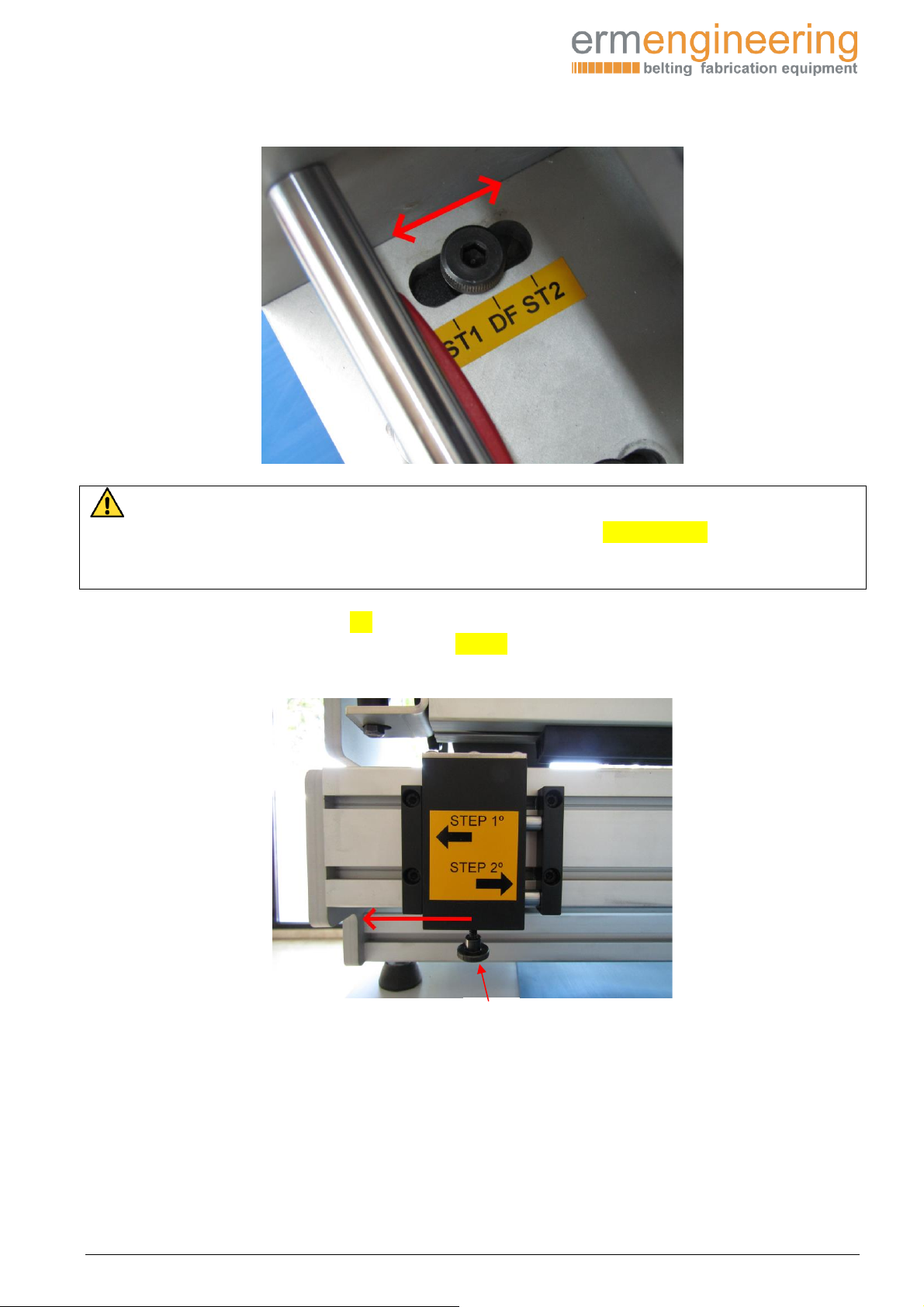
-Spring positioner.
The spring positioner ensures the positioning of the head in the three positions ST1/DF/ST2
To position the head in any of the three points, just pull it up and keeping it retracted, move the
head to the reference mark.
-Start guide positioner.
The function of this mobile guide is to move exactly 10mm (half the pitch of the double finger)
between the STEP 1 and STEP 2 position to make the cut at the second end of the belt.
To position it, simply loosen the lower knurled knob half a turn and move it to the end of its
stroke.

Use and maintenance manual
Manual die cutter
Model: F-121
____________________________________________________________________________________________________________________
P a g . 6
-Pressure regulator knob.
Its function is to regulate and limit the downward path of the die by means of an eccentric shaft.
The lowest set point is 0.
To adjust, pull the knurled knob out, turn into position and lock again.
-Clamp bar pressure flanges.
They fix and immobilize the belt during cutting by pressing the bar down.

Use and maintenance manual
Manual die cutter
Model: F-121
____________________________________________________________________________________________________________________
P a g . 7
Replace cutting head
To change the cutting head, it is necessary to loosen and remove the knob M-6 (B)
Then remove the cutting head from the opposite side.
Replace the cutting head with the one found in the housing that is arranged in the head to
protect it.
(B)

Use and maintenance manual
Manual die cutter
Model: F-121
____________________________________________________________________________________________________________________
P a g . 8
We will introduce the new cutting head from the same side.
And we will fix it later with the knob (B)
WARNING:
When assembling the 80x10 cutting head it is very important that the head is always
positioned in DF. Otherwise, ST1 and ST2 may break the blades on the side guides.
Initial cut measurements before die cutting.
In both types (80x10 and 50x20 double) we will have to cut the belt 100mm longer from the
measure of the final development once it is joined.
Due to the short length of the side guides, it is necessary to cut at 90º with extreme precision.
The positioning reference of the end of the nylon board will determine the straightness of the
splice.
For double die cutting, a minimum of 95mm fabric opening is required.
(B)

Use and maintenance manual
Manual die cutter
Model: F-121
____________________________________________________________________________________________________________________
P a g . 9
Direct die cut 80x10
Preparation
Once the 80x10 cutting head is assembled, we will move the head to the start of the path on the
right side of the bench (0), releasing the locking cam from the lower part of the cutting head by
pressing it down.
Once we have reached the end of the route, we will make sure that the head is in “DF” position
(direct finger), if not, we will position it in the DF position by pulling up the locking knob.
We will move the head to the DF position, making sure that the handle snaps back into the hole.
Use and maintenance manual
Manual die cutter
Model: F-121
____________________________________________________________________________________________________________________
P a g . 10
WARNING:
To be able to position the head in any of the three positions: ST1, DF, ST2; it is essential
that it is at the beginning of the stroke (0) on the right side, otherwise, we could damage
the mechanical elements of the locking cam.
Once the spindle is positioned in DF and with its corresponding cutting head mounted (80x10),
we will position the mobile starting guide in STEP1 and fix it with the lower tightening knob
(A).
(A)

Use and maintenance manual
Manual die cutter
Model: F-121
____________________________________________________________________________________________________________________
P a g . 11
Operation
We will introduce the first end of the belt with the transport or cover face upwards, lifting the
clamping bar through the clamping flanges.
The belt must be inserted until the end of the Nylon plate and well tangent to the initial guide
marked with a green dot (0).
Descend the holding rod by activating the pressure flanges of the clamp on both sides of the
bench.
We will adjust the pressure regulator knob at the 0º point.
To adjust the regulator knob, we will pull the knob out to unlock it.

Use and maintenance manual
Manual die cutter
Model: F-121
____________________________________________________________________________________________________________________
P a g . 12
We will rotate it to the desired position.
Once in position, we will press inwards again to lock it.
We will start the cut from right to left by activating the punching lever until the end of its stroke
and after each cut, we will move the head to the left until it locks again to carry out the next
cutting operation.
We will repeat as many necessary operations until we get the cut in the entire width of the belt.

Use and maintenance manual
Manual die cutter
Model: F-121
____________________________________________________________________________________________________________________
P a g . 13
We will remove the belt and introduce the second end of the belt also with the transport or cover
face up on the opposite side of the bench, lifting the clamping bar and position it to the end of the
Nylon plate and well tangent to the final guide marked with a yellow dot (0).
We will position the head from right to left until the beginning of the belt and we will repeat the
cut in the same way as the previous one, that is, from right to left until the end of its path.

Use and maintenance manual
Manual die cutter
Model: F-121
____________________________________________________________________________________________________________________
P a g . 14
Double finger die cut (50x20)
Preparation
We will introduce the 50x20 cutting head and sit it with knob (B). (See pages 7 and 8)
Once the cutting head is assembled, we will move the head to the end of the path on the right
side of the bench (0), releasing the cutting head locking cam.
We will position the head in position “ST1” to make the first curt of the upper fabric.
To position the “ST1”position head, we will pull up the spring positioner and move the head to
the correct position.

Use and maintenance manual
Manual die cutter
Model: F-121
____________________________________________________________________________________________________________________
P a g . 15
WARNING:
To be able to position the head in any of the three positions: ST1, DF, ST2; it is essential
that it is at the beginning of the stroke (0) on the right side, otherwise, we could damage
the mechanical elements of the locking cam.
Once the head has been positioned and with its corresponding cutting head mounted (50x20),
we will position the mobile guide in STEP1.
Operation
We will introduce the first end of the belt with the transport or cover face up, lifting the clamping
bar and position it until the end of the Nylon plate and perfectly tangent to the initial guide (0)
marked with a green point.

Use and maintenance manual
Manual die cutter
Model: F-121
____________________________________________________________________________________________________________________
P a g . 16
We will lower the clamping bar on both sides of the bench, and we will fix it with the pressure
flanges.
We will adjust the pressure regulator knob at the desired point depending on the thickness of
the lower fabric of the belt (see guide table page ?)
NOTE:
For belt types where the exact pressure setting point is unknown, it is recommended to
first perform a cutting test at position ST2, since even if the setting is incorrect, when
performing the second lower fabric cutting operation, the results of this test will be
deleted.
Once the cutting pressure has been adjusted, we will proceed to the die-cutting of the upper
fabric, carrying out cutting operations from right to left until the width of the belt is finished, we
will remove the waste of the upper fabric.

Use and maintenance manual
Manual die cutter
Model: F-121
____________________________________________________________________________________________________________________
P a g . 17
We will move the head again towards the starting guide marked with the green dot (0) by
releasing the cutting head locking cam, and we will position the head at “ST2” to make the
second cut of the lower fabric.
We will adjust the cutting regulation knob at point 0,
to proceed to the second cut of the lower fabric in the same way, from right to left.

Use and maintenance manual
Manual die cutter
Model: F-121
____________________________________________________________________________________________________________________
P a g . 18
After the cuts are completed at the first end of the belt, we will remove the belt and, to make the
cut at the other end of the belt, we will adjust the mobile guide to STEP2.
We will lift the clamping bar and introduce the belt the other way around, that is, with the fabric
on top and the covering down to the end of the Nylon plate and well tangent to the initial guide
(0) marked with a green dot.
We will lower the clamping bar on both sides of the bench.
We will position the head in position "ST1" to make the first cut of the upper fabric and we will
adjust the pressure regulator knob according to the thickness of the lower fabric.
This graduation for the second end is not related to that of the first end made previously.
NOTE:
For belt types where the exact pressure setting point is unknown, it is recommended to
first perform a cutting test at position ST2, since even if the setting is incorrect, when
performing the second lower fabric cutting operation, the results of this test will be
deleted.

Use and maintenance manual
Manual die cutter
Model: F-121
____________________________________________________________________________________________________________________
P a g . 19
WARNING:
To be able to position the head in any of the three positions: ST1, DF, ST2; it is essential
that it is at the beginning of the stroke (0) on the right side, otherwise, we could damage
the mechanical elements of the locking cam.
We will start the cutting operation from right to left until we cut the entire width of the belt.
We will remove the waste, move the head again to the end of the stroke (0) and position the
head at ST2 and the pressure regulation knob at 0 to cut the lower fabric.
We will lower the clamping bar on both sides of the bench.
We will adjust the pressure mode at the desired point and start the cut from right to left.

Use and maintenance manual
Manual die cutter
Model: F-121
____________________________________________________________________________________________________________________
P a g . 20
For the second cut, we will lift the clamping bar and position it to the end of the Nylon plate and
well tangent to the initial guide (0) marked with a green dot.
We will position the head in position "ST2" to make the second cut of the lower fabric.
We will adjust the pressure knob at point 0.
We will start the cut from right to left until the cut is finished throughout the width of the belt.
Table of contents


