8ENGLISH
6. Blade depth and bevel adjusting locking levers
must be tight and secure before making the
cut.Ifbladeadjustmentshiftswhilecutting,itmay
cause binding and kickback.
7. Use extra caution when sawing into existing
walls or other blind areas. The protruding blade
maycutobjectsthatcancausekickback.
8. ALWAYS hold the tool rmly with both hands.
NEVER place your hand, leg or any part of your
body under the tool base or behind the saw,
especially when making cross-cuts. If kickback
occurs,thesawcouldeasilyjumpbackwardsover
yourhand,leadingtoseriouspersonalinjury.
9. Never force the saw. Push the saw forward at a
speed so that the blade cuts without slowing.
Forcing the saw can cause uneven cuts, loss of
accuracy,andpossiblekickback.
Lower guard function
1. Check the lower guard for proper closing
before each use. Do not operate the saw if the
lower guard does not move freely and close
instantly. Never clamp or tie the lower guard
into the open position.Ifthesawisaccidentally
dropped,thelowerguardmaybebent.Raisethe
lower guard with the retracting handle and make
sureitmovesfreelyanddoesnottouchtheblade
oranyotherpart,inallanglesanddepthsofcut.
2. Check the operation of the lower guard spring.
If the guard and the spring are not operating
properly, they must be serviced before use.
Lowerguardmayoperatesluggishlydueto
damagedparts,gummydeposits,orabuild-upof
debris.
3. The lower guard may be retracted manually
only for special cuts such as “plunge cuts”
and “compound cuts”. Raise the lower guard
by the retracting handle and as soon as the
blade enters the material, the lower guard
must be released. For all other sawing, the lower
guardshouldoperateautomatically.
4. Always observe that the lower guard is cover-
ing the blade before placing the saw down on
bench or oor. An unprotected, coasting blade
will cause the saw to walk backwards, cutting
whatever is in its path. Be aware of the time it
takes for the blade to stop after switch is released.
5. To check lower guard, open lower guard by
hand, then release and watch guard closure.
Also check to see that retracting handle does
not touch tool housing. Leaving blade exposed
is VERY DANGEROUS and can lead to serious
personalinjury.
Additional safety warnings
1. Do not stop the blades by lateral pressure on
the saw blade.
2. Do not attempt to remove cut material when
blade is moving. Wait until blade stops before
grasping cut material. Blades coast after turn off.
3. Place the wider portion of the saw base on
that part of the workpiece which is solidly
supported, not on the section that will fall off
when the cut is made. If the workpiece is short
or small, clamp it down. DO NOT TRY TO HOLD
SHORT PIECES BY HAND!
4. Never attempt to make a cut with the tool held
upside down in a vise. This is extremely dan-
gerous and can lead to serious accidents.
5. Wear safety goggles and hearing protection
during operation.
6. Do not use any abrasive wheels.
7. Only use the saw blade with the diameter that
is marked on the tool or specied in the man-
ual.Useofanincorrectlysizedblademayaffect
the proper guarding of the blade or guard opera-
tionwhichcouldresultinseriouspersonalinjury.
8. Always use the saw blade intended for cutting
the material that you are going to cut.
9. Only use the saw blades that are marked with
a speed equal or higher than the speed marked
on the tool.
10. Before setting the tool down after completing a
cut, be sure that the guard has closed and the
blade has come to a complete stop.
11. Some material contains chemicals which may
be toxic. Take caution to prevent dust inhala-
tion and skin contact. Follow material supplier
safety data.
12. Wear a dust mask and hearing protection when
use the tool.
13. (For European countries only)
Always use the blade which conforms to
EN847-1, when cutting wood or like.
SAVE THESE INSTRUCTIONS.
WARNING: DO NOT let comfort or familiarity
with product (gained from repeated use) replace
strict adherence to safety rules for the subject
product. MISUSE or failure to follow the safety
rules stated in this instruction manual may cause
serious personal injury.
Important safety instructions for
battery cartridge
1. Before using battery cartridge, read all instruc-
tions and cautionary markings on (1) battery
charger, (2) battery, and (3) product using
battery.
2. Do not disassemble battery cartridge.
3. If operating time has become excessively
shorter, stop operating immediately. It may
result in a risk of overheating, possible burns
and even an explosion.
4. If electrolyte gets into your eyes, rinse them
out with clear water and seek medical atten-
tion right away. It may result in loss of your
eyesight.
5. Do not short the battery cartridge:
(1) Do not touch the terminals with any con-
ductive material.
(2) Avoid storing battery cartridge in a con-
tainer with other metal objects such as
nails, coins, etc.
(3) Do not expose battery cartridge to water
or rain.


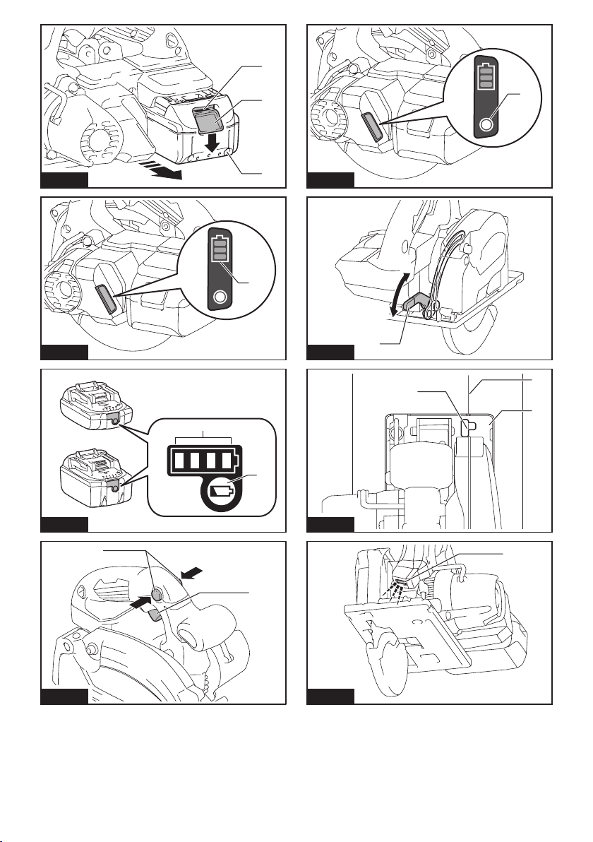
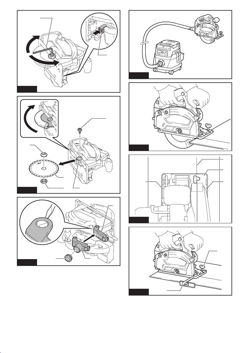
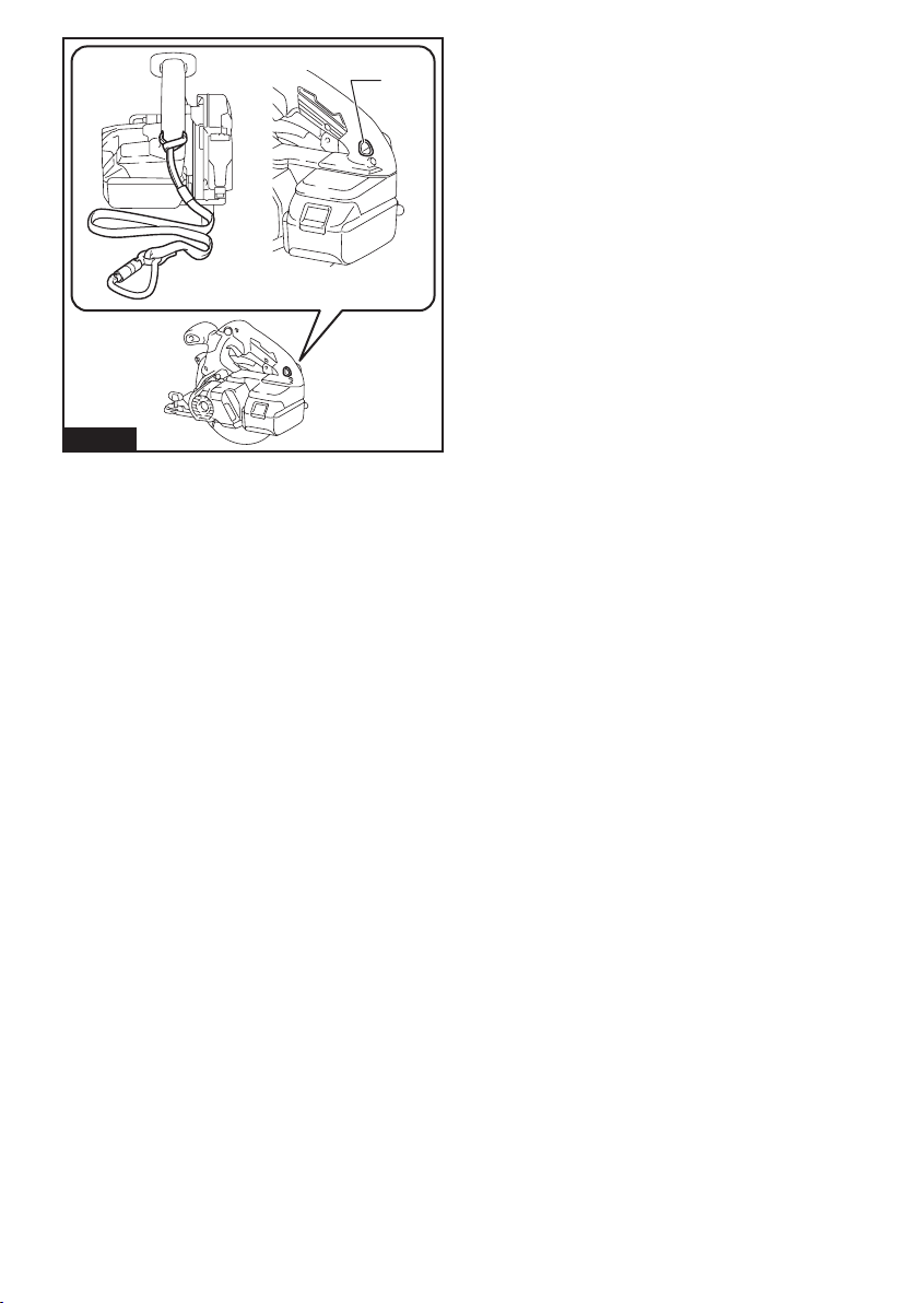
 Quick start guide")