RMG GSM1SPAT User manual

GSM1SPAT - Installation Manual
1
Version 1.0 - 03/2021
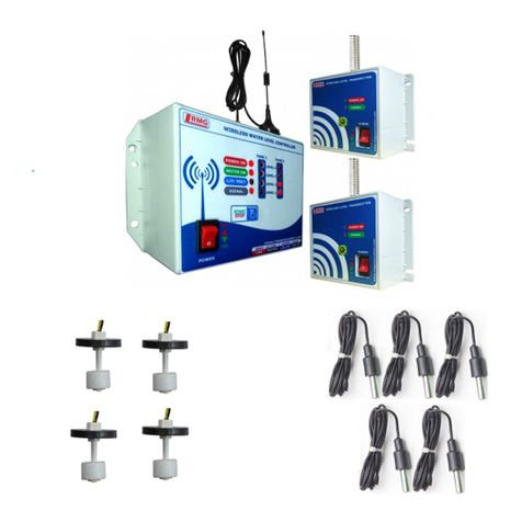
Single/Three Phase Wireless Mobile Water Level Controller
The GSM Mobile Starter is used to switch ON or OFF your motor pump from anywhere in the
world. It will control your motor pump via SMS or giving CALL. Along with this operation, overflow of
water from the tank is prevented by switching off the motor when tank is full.
SIMPLE COMMANDS FOR MOTOR ON/OFF CONTROL WITH YOUR MOBILE
S.No.
SMS COMMAND
TO GSM SIM
EXAMPLE
DESCRIPTION
1
00
00
It denotes the Power ON time.
2
10
10
It will switch OFF the motor pump.
3
11
11
It will switch ON the motor pump.
4
12
12
It gives the ON/OFF status of your motor pump.
5
13
13
It Disables AUTO ON operation when tank is empty.
6
14
14
It Enables AUTO ON operation when tank is empty.
7
70
70
Activates for ANY USERS.
8
71
71
Activates for REG. USERS.
9
80
80
It disables the AUTO REPLY SMS facility.
10
81
81
It enables the AUTO REPLY SMS facility.
11
90
90
It gives the registered users list.
12
9XY
919940594413
92YYYYYYYYYY
93YYYYYYYYYY
It helps to store the user numbers (X-User 1, 2, 3, 4, 5
YYYYYYYYYY-Mobile number). It is same for 4th and 5th
user (94YYYYYYYYYY and 95YYYYYYYYYY)
13
*
*
It helps us to know the setting status.
14
LC0
LC0
It disables 3-Phase Line Checking
15
LC1
LC1
It enables 3-Phase Line Checking
16
FD0
FD0
It disables Feedback Alert for Manual Motor ON / OFF
17
FD1
FD1
It enables Feedback Alert for Manual Motor ON / OFF
18
ASET
ASET
It enables for Automatic Current Setting for Overload and
Dry Run. This command functions only when motor is
running.
19
OLXX
OL15
It helps to enter the overload current setting manually.
Eg. 15 Amps is set as Overload Current.
20
ULXX
UL05
It helps to enter the underload current setting manually.
Eg. 5 Amps is set as Underload Current.
21
STX-HH:MM,HH:MM
ST1-06:00,06:30
ST2-19:00,19:30
ST3-11:15,11:45
ST4-08:00,09:30
ST5-22:00,05:00
It helps to schedule the ON time and OFF time. Totally 5
slots can be scheduled. (Note –Use 24 hour format)
22
SCT
SCT
It lists the scheduled time slots.
23
SCTR
SCTR
It helps to reset the scheduled time slots.
24
T-HH:MM
T-00:20
It helps us to use as a Delay / Stop Timer. Motor get ON
once the time is set and will get switched OFF after the set
time is over. Eg. After 20 minutes, motor will get OFF.

GSM1SPAT - Installation Manual
2
Version 1.0 - 03/2021
MISSED CALL FOR ON/OFF CONTROL
MOTOR ON/OFF COMMAND
MESSAGE
S.No
COMMAND
DESCRIPTION
S.No
COMMAND SMS
DESCRIPTION
1
Call cuts off after Long ring (>4)
MOTOR ON
1
11
MOTOR ON
2
Call cuts off after Short ring (>2)
MOTOR OFF
2
10
MOTOR OFF
Starter Connection Diagram:
Picture 1.
Installation steps of GSM Controller:
Caution: Switch off the main power while doing the Power Connection steps.
Step 1: Insert your GSM SIM in the SIM slot given as shown in the GSM controller.
Step 2: Wall mount the GSM controller by using the screws in the given slots on its sides.
Step 3: Remove the ‘R’ wire from starter & insert into the CT coil, and connect it back to the
starter.
Step 4: Connect L1, L2, L3 to R, Y, B input line of the starter respectively.
Step 5: In your starter, Connect Blue pair wire of the controller to the start button in parallel as
shown in the Picture 1.
Step 6: Trace the wire that connects the start and stop button terminals. Remove this wire
from the stop button and join it with the any one black wire of Relay Black Pair.
Step 7: Connect the Left out black wire of Relay Black Pair to the stop button where the wire
was removed as shown in the Picture 1.
Step 8: Connect the GSM antenna in the slot provided on the left side of the controller.
Step 9: Connect the sensor output to the water float switch through 4 pair communication
cable.
If the starter is not matching with the above suggested connection kindly What’s app us on
9940594413 or call 044-43180017 for support!!!!!
Share the starter photo front panel and opened panel photo in what’s app.
Step 7: Verify all the connections and then Switch ON the controller.
STARTER
Start button
Blue pair wire
Black pair wire
Stop button
CONTACTOR
Y
CT COIL
R
B

GSM1SPAT - Installation Manual
3
Version 1.0 - 03/2021
Operating procedure:
Step 1: Switch ON the controller with the help of a button provided on its left side. Power ON
LED will get ON.
Step 2: After few seconds, GSM “Signal” LED blinks every one sec trying to get connected to the
network. Further, it blinks every 3 sec that ensures the GSM has been connected to the
network.
Step 3: The “SIM READY” LED will blink for some time and then glow constantly. The constant
glowing indicates that SIM is ready and connected to the network. In this condition, you can
access the GSM controller to control the motor pump.
Step 4: Send SMS to the GSM SIM as “91YYYYYYYYYY” (Y is your 10 digit mobile number).
Below is the message that you will receive. (For registering other 4 users, refer Command
Table on the Top)
Step 5: Send SMS to the GSM SIM as “81” if AUTO REPLY from GSM SIM is required.
Step 6: Send SMS Command “11” for motor pump ON and “10” for motor pump OFF.
Step 7: Motor Pump can be turned ON/OFF by giving a call also. While giving a call to the GSM
SIM, the controller will cut the call after 4 rings and switch ON the motor pump (when the
pump is OFF). Similarly, by giving another call, the controller will cut the call after 2 rings and
switch OFF the pump (when pump is ON). We can ensure the status of motor whether it is ON
or OFF with the number of rings also.
Step 8: To know the status of the motor pump use the command “12”.
Step 9: For automatic operation, send command “14”, motor automatically starts and stops
based on the water level. When tank is empty, motor gets ON and when tank is full, motor gets
OFF.
Step 10: For other operations, refer table (Page 1) for the commands.
NOTE: Do not use “ “ double quotes while sending the SMS.

GSM1SPAT - Installation Manual
4
Version 1.0 - 03/2021
Trouble shooting:
Power Fail:
Check whether input supply is correctly given.
Check whether the GSM power switch position is “ON”.
Check fuse is in good condition. If fuse is failed or burnt replace it with 300 Milliamps.
Don’t use more than that.
Motor not switching ON:
Start Relay:
Check whether connection of start relay (Blue pair wire) is properly given.
Check start relay - It must be Normally Open. Start relay will become closed for 1-3
seconds while motor ON. Verify it using continuity tester or Multi-meter.
Motor not switching OFF:
Stop Relay:
Check whether connection of stop relay (Black pair wire) is properly given.
Check stop relay - It must be Normally Closed. Stop relay will become open for 3
seconds while motor OFF. Verify it using continuity tester or Multi-meter.
SMS/CALL not working:
SIM card:
Check if SIM card is properly inserted as per the image shown in the GSM unit.
Make sure that SIM Card has 2G support. Don’t use SIM Cards that support 4G alone
like JIO SIM.
GSM antenna location:
Keep it outside and don’t enclose it.
Antenna wire laying:
Make sure that GSM antenna wire is laid separately. Don’t take it along with power
wires.
GSM signal LED:
Check if it is blinking for every 3 seconds –Network connected.
If blinking every 1 second –Network Issue –Change another good network SIM card.
NOTE: For further assistance please do contact us on what’s app 9940594413.
Table of contents
Other RMG Controllers manuals
Popular Controllers manuals by other brands

LOVATO ELECTRIC
LOVATO ELECTRIC DCRG8 installation manual

Lumatek
Lumatek LUMBC006 manual
Rain Bird
Rain Bird CRC-8A Programming and operating instructions
Omega Engineering
Omega Engineering DP25-TH quick start

Neets Control
Neets Control Alfa manual
PS Automation
PS Automation PSF301 Short operating instructions

