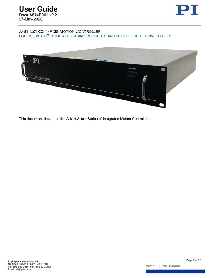
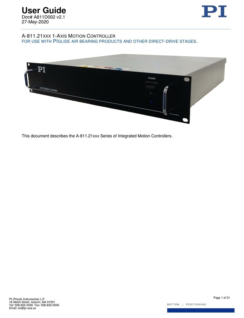
PI A-824.21 Series User manual

User Guide
Doc# A824D001 v2.0
15-Nov-2018
Page 1 of 28
PI (Physik Instrumente) L.P.
16 Albert Street, Auburn, MA 01501
Tel: 508-832-3456 Fax: 508-832-0506
Email: air@pi-usa.us
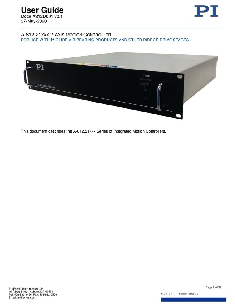
A-824.21XXX 4-AXIS HI-POWER MOTION CONTROLLER
FOR USE WITH PIGLIDE AIR BEARING PRODUCTS AND OTHER DIRECT-DRIVE STAGES.

User Guide
Doc# A824D001 v2.0
15-Nov-2018
Page 2 of 28
PI (Physik Instrumente) L.P.
16 Albert Street, Auburn, MA 01501
Tel: 508-832-3456 Fax: 508-832-0506
Email: air@pi-usa.us
Physik Instrumente (PI) GmbH & Co. KG is the owner of the following trademarks:
PI®, PIC®, PICMA®, PILine®, PIFOC®, PiezoWalk®, NEXACT®, NEXLINE®, NanoCube®, NanoAutomation®,
Picoactuator®, PInano®, PIMag®
PI owns the following patents or patent applications for the technology field Magnetic Direct Drives (PIMag®):
WO212146709A2, DE102012207082A1
© 2018 PI (Physik Instrumente) L.P. The text, photographs and drawings in this user guide are protected by
copyright. With regard thereto, PI (Physik Instrumente) L.P. retains all the rights. Use of said text, photographs
and drawings is permitted only in part and only upon citation of the source.
Subject to change without notice. This user guide is superseded by any new release. PI continually improves its
product offerings, and listed options and specifications may be superseded at any time.

User Guide
Doc# A824D001 v2.0
15-Nov-2018
Page 3 of 28
PI (Physik Instrumente) L.P.
16 Albert Street, Auburn, MA 01501
Tel: 508-832-3456 Fax: 508-832-0506
Email: air@pi-usa.us
Table of Contents
1. About this Document..................................................................................................................................................5
1.1. Objective and Target Audience of this User Guide .....................................................................................................5
1.2. Symbols and Typographic Conventions ......................................................................................................................5
1.3. Other Applicable Documents ......................................................................................................................................5
2. Safety..........................................................................................................................................................................6
2.1. Intended Use ...............................................................................................................................................................6
2.2. General Safety Instructions.........................................................................................................................................6
2.3. Organizational Measures............................................................................................................................................6
2.4. Personnel Qualification...............................................................................................................................................6
2.5. Warnings and Safety Notices......................................................................................................................................7
3. Unpacking...................................................................................................................................................................7
4. Product Overview .......................................................................................................................................................8
4.1. Model Overview and Part Numbering ........................................................................................................................8
4.2. Product Description.....................................................................................................................................................8
4.3. Product Features.........................................................................................................................................................8
4.4. Product Views .............................................................................................................................................................9
4.5. Product Labeling .......................................................................................................................................................10
4.6. Scope of Delivery.......................................................................................................................................................11
4.7. Upgrade Options.......................................................................................................................................................11
5. Mounting..................................................................................................................................................................12
6. Connecting the Cables ..............................................................................................................................................12
7. Hardware Interlock ...................................................................................................................................................12
8. Connecting the Controller to Protective Earth ..........................................................................................................13
9. User I/O ....................................................................................................................................................................14
9.1. Analog Inputs............................................................................................................................................................14
9.2. Analog Outputs .........................................................................................................................................................14
9.3. Digital I/O .................................................................................................................................................................15
10. Axis Numbering.....................................................................................................................................................17
11. Software Installation on Host PC...........................................................................................................................18
12. Establishing Host PC Communications with the Controller....................................................................................18
13. Operation..............................................................................................................................................................19

User Guide
Doc# A824D001 v2.0
15-Nov-2018
Page 4 of 28
PI (Physik Instrumente) L.P.
16 Albert Street, Auburn, MA 01501
Tel: 508-832-3456 Fax: 508-832-0506
Email: air@pi-usa.us
13.1. Basic Setup............................................................................................................................................................19
13.2. Homing and Initialization......................................................................................................................................20
13.3. Simple Motion.......................................................................................................................................................21
13.4. Cycle Program.......................................................................................................................................................22
13.5. Servo Tuning .........................................................................................................................................................22
14. Maintenance.........................................................................................................................................................23
14.1. Updating Firmware...............................................................................................................................................23
14.2. Cleaning ................................................................................................................................................................23
15. Customer Service ..................................................................................................................................................23
16. Technical Data.......................................................................................................................................................24
16.1. Specifications ........................................................................................................................................................24
16.2. Ambient Conditions...............................................................................................................................................24
16.3. Dimensions............................................................................................................................................................25
16.4. Connector Pin Assignments...................................................................................................................................26
17. EC Declaration of Conformity ................................................................................................................................28
18. Old Equipment Disposal ........................................................................................................................................28
Table of Figures
Figure 1 - Front panel of A-824.21xxx motion controller 9
Figure 2 - Rear panel of A-824.21xxx motion controller 9
Figure 3 - Product Labeling Example 10
Figure 4 - Interlock Bypass Jumper 13
Figure 5 - Chassis Protective Earth Stud Location 13
Figure 6 - Attaching the Protective Earth Conductor 14
Figure 7 - Variables Manager and Watch Dialog 15
Figure 8 - Inputs / Outputs Manager 15
Figure 9 - Suggested PC LAN Adapter Settings 18
Figure 10 - Connect to Controller Dialog 19
Figure 11 - Controller Object –List of Typical Components 20
Figure 12 - Motion Manager 21
Figure 13 - Back and Forth Motion 21
Figure 14 - Buffer Window 22
Figure 15 - A-824.21xxx Dimensions 25

User Guide
Doc# A824D001 v2.0
15-Nov-2018
Page 5 of 28
PI (Physik Instrumente) L.P.
16 Albert Street, Auburn, MA 01501
Tel: 508-832-3456 Fax: 508-832-0506
Email: air@pi-usa.us
1. About this Document
1.1. Objective and Target Audience of this User Guide
This User Guide contains information on the intended use of the A-824.21xxx series of motion controllers,
hereinafter referred to as the “A-824”. It assumes that the reader has a fundamental understanding of basic
servo systems as well as motion control concepts and applicable safety procedures.
1.2. Symbols and Typographic Conventions
The following symbols and markings are used in this User Guide:
Symbol
Meaning
If not avoided, the situation could result in damage to the equipment.
Failure to observe these precautions could result in serious injury to
those performing the procedures and damage to the equipment.
1.
2.
Action consisting of several steps whose sequential order must be
observed
Action consisting of one or several steps whose sequential order is
irrelevant
1.3. Other Applicable Documents
Name
Instructions for SPiiPlus ADK Suite Installation
ACSPL Plus Programmer's Guide
SPiiPlus MMI Application Studio User Guide
SPiiPlus Command and Variable Reference Guide
SPiiPlus C Library Reference Programmer Guide
SPiiPlus COM Library Programmers Guide
SPiiPlus NET Programmers Guide
App Note - PEG and MARK Operations

User Guide
Doc# A824D001 v2.0
15-Nov-2018
Page 6 of 28
PI (Physik Instrumente) L.P.
16 Albert Street, Auburn, MA 01501
Tel: 508-832-3456 Fax: 508-832-0506
Email: air@pi-usa.us
2. Safety
2.1. Intended Use
The A-824 is a laboratory device according to DIN EN 61010-1. It is intended to be used in interior spaces and in
an environment which is free of dirt, oil and lubricants.
According to its design, the A-824 is intended for operating the PIglide line of direct-drive air bearing linear and
rotary stages. Do not attempt to connect the A-824 to any other device unless specifically instructed to do so by a
PI engineer.
The A-824 may only be used in compliance with the technical specifications and instructions in this User Guide.
The user is responsible for process validation and application software development.
2.2. General Safety Instructions
The A-824 is built according to state-of-the-art technology and recognized safety standards. Improper use can
result in personal injury and/or damage to the A-824.
Only use the A-824 for its intended purpose, and only use it if it is in a good working order.
Read the user documentation.
Immediately eliminate any faults and malfunctions that are likely to affect safety.
The operator is responsible for the correct installation and operation of the A-824.
Install the A-824 near the power source so that the power plug can be quickly and easily disconnected from
the mains.
Use the supplied components to connect the A-824 to the power source.
2.3. Organizational Measures
Always keep this user guide available by the A-824.
The latest versions of the user guide are available from PI.
Add all information given by the manufacturer to the user documentation, for example supplements or
Technical Notes.
If you give the A-824 to other users, also turn over the user documentation as well as other relevant
information provided by the manufacturer.
Only use the device on the basis of the complete user documentation. Missing information due to incomplete
user documentation can result in property damage.
Only install and operate the A-824 after having read and understood this user guide.
2.4. Personnel Qualification
The A-824 may only be installed, started up, operated, maintained and cleaned by authorized and qualified staff.

User Guide
Doc# A824D001 v2.0
15-Nov-2018
Page 7 of 28
PI (Physik Instrumente) L.P.
16 Albert Street, Auburn, MA 01501
Tel: 508-832-3456 Fax: 508-832-0506
Email: air@pi-usa.us
2.5. Warnings and Safety Notices
The following statements apply throughout this user guide. Failure to observe these precautions could result in
serious injury to those performing the procedures and damage to the equipment. This user guide and any
additional instructions included with the stage should be retained for the lifetime of the stage.
To minimize the possibility of electrical shock and bodily injury or death, disconnect all electrical
power prior to making any electrical connections.
To minimize the possibility of electrical shock and bodily injury or death when any electrical circuit
is in use, ensure that no person comes in contact with the circuitry when the stage or controller is
connected to a power source.
To minimize the possibility of bodily injury or death, disconnect all electrical power prior to making
any mechanical adjustments.
To minimize the possibility of bodily injury or death from electric shock in the case of malfunction or
failure of the system, make sure a protective earth conductor is properly connected.
Moving parts of the stage can cause crushing or shearing injuries. All personnel must remain clear
of any moving parts.
Improper use of the equipment can cause damage, shock, injury, or death. Read and understand
this user guide before operating the stage.
If the equipment is used in a manner not specified by the manufacturer, the protection provided by
the equipment can be impaired.
Interconnect cables can pose a tripping hazard. Securely mount and position all stage cables to
avoid potential hazards.
Do not expose the equipment to environments or conditions outside the specified range of
operating environments. Operation in conditions other than those specified can cause damage to
the equipment.
The equipment must be mounted securely. Improper mounting can result in injury and damage to
the equipment.
Use care when moving the equipment. Lifting or transporting stages can result in injury.
Use care when moving the equipment. Avoid any shocks, drops or bumps that can cause
scratches, dings, dents, or distortion of the equipment.
3. Unpacking
Carefully unpack the controller, stages, and other components from the shipping packaging. Inspect the contents
for signs of damage. If there is any sign of damage or missing parts, contact PI immediately. Keep all packaging
materials in case the product needs to be returned.

User Guide
Doc# A824D001 v2.0
15-Nov-2018
Page 8 of 28
PI (Physik Instrumente) L.P.
16 Albert Street, Auburn, MA 01501
Tel: 508-832-3456 Fax: 508-832-0506
Email: air@pi-usa.us
4. Product Overview
4.1. Model Overview and Part Numbering
The A-824 series offers various models, defined by the encoder type, communications protocol, and IO options.
Model
Encoder
Options
A-824.21
A = Incremental Sine (1 Vp-p)
Interpolation 4x to 16,384x
00 = Ethernet Communications
72 VDC Motor Bus
24V IO
B = Absolute BiSS-C
4.2. Product Description
The A-82x series of high-power motion controllers from PI offers a completely integrated electronics solution, with
controller, drives, and power supplies packaged together in a compact 4U, 19-inch rack-mount enclosure. These
controllers are designed and optimized to work with the PIglide line of air bearing stages which feature direct
drive linear and rotary servo motors and high resolution encoders. The A-824.21xxx series features the UDMnt
PWM servo drive from ACS, which offers the excellent performance at a reduced cost.
Standard options include inputs for incremental sine encoders and absolute encoders using the BiSS-C serial
data protocol. Sine encoder support includes integrated encoder multiplication up to 16,384x. All controllers
feature on-board flash memory for stored motion programs and parameters. The A-82x controllers can run in
standalone mode running stored programs, or controlled via an external PC. A PC is required for programming
and setup. All software is included with the controller.
4.3. Product Features
ACS SPiiPlus EC Motion Controller and EtherCAT® master.
ACS UDMnt PWM servo drives
AC-to-DC power supplies to convert AC line voltage into the required DC voltages needed for the servo
motors and controller logic.
Cooling Fan
Circuit breakers built into on/off power switch
Cabling to bring all necessary electrical signals to the rear panel, using industry-standard D-sub connectors
on the package exterior.
19” wide rack-mount chassis.
Incremental SIN/COS Analog encoder inputs with 4096x Interpolation.
Absolute BiSS-C encoder inputs.
(Note: The standard model configuration assumes that all axes of the A-8xx are configured for the same
encoder type. However, custom configurations can be offered that allow mixing of the encoder types
between axes).
Universal AC Power Input. For maximum performance, the A-82x series should only be used with AC input
voltages of 200 - 265VAC (single phase) 50-60 Hz.)
MPU cycle rate of 5 kHz.
Can operate DC servo, voice-coil, and 3-phase brushless servo motors.
Encoder-based sine commutation (no Hall Effect sensors needed) of 3-phase motors.
16 buffers for stored motion programs.
24VDC IO and limits.
24VDC interlock input.
EtherCAT® output port for expansion to more axes, expanded IO, LCMv2 laser control module, and more.
Ethernet (TCP/IP) communications to host PC. Ethernet/IP also supported.

User Guide
Doc# A824D001 v2.0
15-Nov-2018
Page 9 of 28
PI (Physik Instrumente) L.P.
16 Albert Street, Auburn, MA 01501
Tel: 508-832-3456 Fax: 508-832-0506
Email: air@pi-usa.us
All required software drivers.
ACS SPiiPlus ADK Suite of software tools. Includes SPiiPlus MMI Application Studio, SPiiPlus Utilities for
software maintenance and application management, Full documentation of all ACS products and software
tools, Full controller simulator.
4.4. Product Views
Figure 1 - Front panel of A-824.21xxx motion controller
Figure 2 - Rear panel of A-824.21xxx motion controller

User Guide
Doc# A824D001 v2.0
15-Nov-2018
Page 10 of 28
PI (Physik Instrumente) L.P.
16 Albert Street, Auburn, MA 01501
Tel: 508-832-3456 Fax: 508-832-0506
Email: air@pi-usa.us
Labeling
Type
Function
AC INPUT
IEC 60320 Type C20
Connection for the AC supply voltage
ETHERNET
RJ45 Socket
Connection to the host PC
ETHERCAT OUT
RJ45 Socket
Connection to ACS Controller EtherCAT Bus
INTERLOCK
DB9-F
E-Stop/Interlock Connection
ANALOG IO
DB9-M
Controller Analog I/O Connection
DIGITAL IO
DB25-F
Controller Digital I/O Connection
ENCODER 1
DB15-F
Stage Encoder Connection Axis #1
MOTOR 1
DB9W4-F
Stage Motor Connection Axis #1
ENCODER 2
DB15-F
Stage Encoder Connection Axis #2
MOTOR 2
DB9W4-F
Stage Motor Connection Axis #2
ENCODER 3
DB15-F
Stage Encoder Connection Axis #3
MOTOR 3
DB9W4-F
Stage Motor Connection Axis #3
ENCODER 4
DB15-F
Stage Encoder Connection Axis #4
MOTOR 4
DB9W4-F
Stage Motor Connection Axis #4
See Section 16.4 for connector pin assignments.
4.5. Product Labeling
Figure 3 - Product Labeling Example
#
Description
1.
A-824.21A00 (Product model number example)
2.
Serial number (example), individual for each A-824
Meaning of the places (counting from left):
A = PIglide Air Bearing Product
17 = year of manufacture (i.e. 2017)
242402 = consecutive unique number, 6-digit
3.
Warning sign "Observe manual"
4.
Old equipment disposal warning sign
5.
CE mark
6.
Country of origin
7.
Manufacturer's address (website)
8.
Manufacturer's logo

User Guide
Doc# A824D001 v2.0
15-Nov-2018
Page 11 of 28
PI (Physik Instrumente) L.P.
16 Albert Street, Auburn, MA 01501
Tel: 508-832-3456 Fax: 508-832-0506
Email: air@pi-usa.us
4.6. Scope of Delivery
Item number
Description
A-824.21xxx
4-Axis Motion Controller, 4U 19” rack mount enclosure
ACS SPiiPlus EC Controller & UDMnt Drives
200-240 VAC Input
Configuration per the sales order.
AS002E006
Power cord, 20 A, 250 VAC, 2 pole plus ground
IEC 60320 C19
Plug End Socket End
000056566
CAT5e Patch Cable, Shielded, 10 ft.
-
USB Memory Stick and/or CR-ROM and/or DVD with documentation and software,
including controller parameter backup files
A824D001
User Guide for the A-824 (this document)
4.7. Upgrade Options
The ACS SPiiPlus EC Motion Controller contained inside the A-82x series controller can be upgraded at the
factory or in the field to add the following features. Contact a PI sales engineer for details and pricing.
Increase the number of axes that can be controlled (up to 64 (note this does not add drive axes).
Add ServoBoost™(in blocks of 4 axes). ServoBoost™ provides:
Automatic adaptation to large changes in load and system parameters
Automatic compensation of disturbances, resonances, axes interaction, cogging and more)
ServoBoost™ is required for gantry applications.
Add ServoBoost™PLUS (requires at least 4 axes of ServoBoost™already installed). ServoBoost™ PLUS
provides:
Improved stability and jitter performance
Improved velocity stability
G-Code programming
Input Shaping for increased step-and settle performance and decreased reaction force motion.
Add additional programming buffers for stored motion programs (up to 64 total).

User Guide
Doc# A824D001 v2.0
15-Nov-2018
Page 12 of 28
PI (Physik Instrumente) L.P.
16 Albert Street, Auburn, MA 01501
Tel: 508-832-3456 Fax: 508-832-0506
Email: air@pi-usa.us
5. Mounting
The A-824 is intended for either desktop use or to be mounted in a 19” wide electrical rack using the mounting
holes on the front panel. Mounting holes for side-mounted slide rails are included; the rails themselves are not
included.
Take care not to block the air inlet and exhaust ports on either side if the chassis, otherwise the
controller could overheat.
6. Connecting the Cables
Stage interconnect cables are not in the scope of delivery of the A-824. However, PI offers several standard
cable sets that can be used, depending on the motion controller options being used. See Section 16.4 for
connector pin assignments.
Only use the interconnect cables that have been designed for the combination of stage and
controller being used. Connection using the wrong cable may result in damage to the stage and
the controller.
To minimize the possibility of electrical shock and bodily injury or death, disconnect all electrical
power prior to making any electrical connections.
To minimize the possibility of electrical shock and bodily injury or death when any electrical
circuit is in use, ensure that no person comes in contact with the circuitry when the stage is
connected to a power source.
To minimize the possibility of bodily injury or death, disconnect all electrical power prior to
making any mechanical adjustments.
Prior to electrically connecting the stage to the A-824 controller, follow the instructions in the stage’s user guide
for proper mounting of the stage and the stage payload.
1. Connect the #1 stage motor connector to the A-824 “Motor 1” connector with the proper interconnect cable.
2. Connect the #1 stage encoder connector to the A-824 “Encoder 1”connector with the proper interconnect
cable.
3. Repeat steps 1 & 2 for axes #2 through #4 as needed.
4. Connect the air pressure switch on the Air Prep Kit (if purchased) to the A-824 “Interlock” connector with the
proper interconnect cable.
5. Ensure that all cable connector screws are securely fastened, but do not overtighten.
6. Connect the A-824 to the host PC using an Ethernet patch cable.
7. Connect the A-824 power input connector to an AC outlet using the power cord provided with the controller.
When ready to use, switch on the controller power using the power switch located on the front of the A-824. A
blue power-on indicator light on the front of the A-824 will turn on.
7. Hardware Interlock
The controller has an interlock input that needs to be connected to a +24 VDC source for the servo drives to run;
otherwise the controller will be in the “Interlock fault”state; no motion can be commanded and the motors cannot
be energized. See Section 16.4 for connector pin assignments.
The interlock is typically connected (in series to a +24VDC supply) to an air pressure switch on a PI-supplied A-
80x series air prep kit. In the event of an air pressure loss, the switch will open and the interlock will disable the
servo drives.

User Guide
Doc# A824D001 v2.0
15-Nov-2018
Page 13 of 28
PI (Physik Instrumente) L.P.
16 Albert Street, Auburn, MA 01501
Tel: 508-832-3456 Fax: 508-832-0506
Email: air@pi-usa.us
The Interlock cable which connects the air pressure switch on the air prep kit (if purchased) includes a 2-pin
connector (Molex Part# 43640-0201) that can be used by the end user to connect additional interlock devices.
The two pins can be connected in series to various 24 VDC devices, such as E-stop switches, door switches,
light curtains, etc. Integrating these functions is the decision and the responsibility of the user.
The Interlock cable is shipped with a bypass jumper installed. If the jumper is installed, the user interlock is
bypassed, and only the air pressure switch is used by the controller’s interlock circuit.
Figure 4 - Interlock Bypass Jumper
To completely bypass all interlock functionality of the A-824, connect +24VDC to the INTLOCK1 pin on the A-
824’s Interlock connector.
8. Connecting the Controller to Protective Earth
To minimize the possibility of bodily injury or death from electric shock in the case of malfunction or
failure of the system, make sure a protective earth conductor is properly connected.
The A-824 has two (2) M4 threaded studs for connecting the controller chassis to a protective earth ground
conductor. The studs are marked with the symbol for the protective earth ground and are located on the rear
panel of the controller near the upper corners.
Figure 5 - Chassis Protective Earth Stud Location
The fasteners needed to attach a protective earth conductor are included with the A-824, with a full set
mounted to each ground stud.
The protective earth conductor cable cross-section should be ≥0.75 mm2(20 AWG or heavier).

User Guide
Doc# A824D001 v2.0
15-Nov-2018
Page 14 of 28
PI (Physik Instrumente) L.P.
16 Albert Street, Auburn, MA 01501
Tel: 508-832-3456 Fax: 508-832-0506
Email: air@pi-usa.us
To connect the controller to a protective earth conductor:
1. If necessary, fasten a suitable cable lug to the protective earth conductor. Note that the conductor and lug
are not in the scope of delivery of the A-824.
2. Remove the fasteners (M4 nut, two safety “star” washers, and two flat washers) from the stud.
3. Attach the cable lug of the protective earth conductor to the protective earth stud using the fasteners as
shown:
Figure 6 - Attaching the Protective Earth Conductor
#
Description
1.
Chassis stud (M4 male)
2.
Star washer (2x)
3.
Flat washer (2x)
4.
Cable lug
5.
M4 Nut
6.
Protective earth conductor
4. Tighten the M4 nut with a torque of 1.2 Nm to 1.5 Nm.
5. Make sure that the contact resistance at all connection points relevant for mounting the protective earth
conductor is <0.1 Ω at 25 A.
9. User I/O
9.1. Analog Inputs
2x
Variables: AIN 0, AIN 2
Resolution: 12-bit
Range: Differential, +\- 10 VDC
Input resistance: >160 kΩ
Default Scaling: The programming range, in real numbers, is from -100 to +100. Measured across the AIN0
+ pin and AIN0 - pin, this corresponds to an input voltage of -10VDC to +10VDC.
9.2. Analog Outputs
2x
Variables: AOUT 0, AOUT 1
Resolution: 10-bit
Range: Differential, +/- 10 VDC
Max output current: 1 mA
Default Scaling: The programming range, in real numbers, is from -100 to +100. Measured across the
AOUT0 + pin and AOUT0 - pin, this corresponds to an output voltage of -10VDC to +10VDC.

User Guide
Doc# A824D001 v2.0
15-Nov-2018
Page 15 of 28
PI (Physik Instrumente) L.P.
16 Albert Street, Auburn, MA 01501
Tel: 508-832-3456 Fax: 508-832-0506
Email: air@pi-usa.us
Programming Note: The Analog Input and Output objects can be accessed through the “Variables Manager and
Watch” object in the ACS MMI. Select the desired IO object from the “Variables” list, then click “Create Watch”.
Figure 7 - Variables Manager and Watch Dialog
9.3. Digital I/O
The A-824 provides four (4) general purpose digital inputs and three (3) general purpose digital outputs. These
are in addition to the inputs used for travel limit switches. All are opto-isolated.
Programming Note: The general purpose input and output objects can be accessed through the “Inputs /
Outputs Manager” object in the ACS MMI. Outputs can be toggled by clicking on the green square of the desired
output. Input status is indicated by the green circles.
Figure 8 - Inputs / Outputs Manager

User Guide
Doc# A824D001 v2.0
15-Nov-2018
Page 16 of 28
PI (Physik Instrumente) L.P.
16 Albert Street, Auburn, MA 01501
Tel: 508-832-3456 Fax: 508-832-0506
Email: air@pi-usa.us
9.3.1. General Purpose Inputs
4x
Variables: Drive0 IN 1, Drive0 IN 2, Drive 0 IN 3, Drive 1 IN 1
Current Sinking (NPN)
Voltage: 24 VDC
Input current: < 5 mA
9.3.2. General Purpose Outputs
3x
Drive0 OUT 1, Drive 1 OUT 0, Drive 1 OUT 1
Current Sourcing (PNP)
Voltage: 24 VDC
Output Current: 100 mA max

User Guide
Doc# A824D001 v2.0
15-Nov-2018
Page 17 of 28
PI (Physik Instrumente) L.P.
16 Albert Street, Auburn, MA 01501
Tel: 508-832-3456 Fax: 508-832-0506
Email: air@pi-usa.us
9.3.3. High Speed IO (PEG)
In addition to the general purpose DIO, the A-824 includes four (4) additional high-speed TTL-level (RS-422)
outputs used for the Position Event Generator (PEG) to trigger external events based on real-time position data.
See the ACS document “App Note - PEG and MARK Operations” for more details.
Signal Type: RS-422
Pulse width: 26 nsec –1.75 msec
Max Rate: 10 MHz
10. Axis Numbering
The following mapping applies between the Axis Number used in the ACS controller software and the hardware
ports on the A-824:
Axis #
Hardware Port
0
Motor 1, Encoder 1
1
Motor 2, Encoder 2
2
Motor 3, Encoder 3
3
Motor 4, Encoder 4

User Guide
Doc# A824D001 v2.0
15-Nov-2018
Page 18 of 28
PI (Physik Instrumente) L.P.
16 Albert Street, Auburn, MA 01501
Tel: 508-832-3456 Fax: 508-832-0506
Email: air@pi-usa.us
11. Software Installation on Host PC
1. Copy the file “SPiiPlus ADK Suite v.2.30 Update 2.zip” from the provided USB Memory stick/CD-ROM/DVD
to a local folder on the user’s host PC.
The software can also be downloaded from: https://www.acsmotioncontrol.com/downloads. You may
need to create a user account to access these materials.
2. Unzip the file.
3. Follow the instructions in the “Instructions for SPiiPlus ADK Suite v2 30 Installation”.
4. Run the file “setup.exe” located in the folder to which the .zip file was unpacked.
12. Establishing Host PC Communications with the Controller
Communication with a host PC is necessary to operate the controller in non-autonomous mode. Note that it is
possible to operate the controller without a host PC; however motion programs must first be saved to the
controller’s non-volatile memory.
To connect the host PC to the A-824 controller:
1. Make sure the A-824 and the host PC are connected by an Ethernet patch cable.
2. You may need to adjust your PC’s LAN adapter settings to talk locally to the A-824. The following figure
shows suggested settings for your PC’s LAN adapter:
Figure 9 - Suggested PC LAN Adapter Settings

User Guide
Doc# A824D001 v2.0
15-Nov-2018
Page 19 of 28
PI (Physik Instrumente) L.P.
16 Albert Street, Auburn, MA 01501
Tel: 508-832-3456 Fax: 508-832-0506
Email: air@pi-usa.us
3. Turn on the power on the A-824 using the switch on the front panel.
4. Start the SPiiPlus MMI Application Studio software on the host PC.
5. Click “Add Controller” on the main menu toolbar.
6. In the “Connect to Controller” dialog, give your controller a name, select the “Ethernet” tab, and enter IP
address 10.0.0.100, Port 701. This is the default IP address of the A-824 controller set at the factory.
Figure 10 - Connect to Controller Dialog
See the ACS document “SPiiPlus MMI Application Studio User Guide” for details on connecting to the controller.
For additional tutorials on the use of the MMI software, see https://www.acsmotioncontrol.com/downloads and
click under the “Training Materials” section. You may need to create a user account to access these materials.
13. Operation
The SPiiPlus MMI Application Studio software can be used to control the system, to develop user programs, and
to alter the system configuration. For complete instructions, see the ACS documentation provided with this
system.
Note: The SPiiPlus MMI Application Studio software also has extensive online help. To access it, press
“F1” from any screen in the program.
13.1. Basic Setup
To access the most-used features of the MMI, you must add components to the controller object. The following
figure shows a typical setup. Components can be added by right-clicking on the controller object in the
Workspace area of the MMI, then selecting “Add Component”, then selecting the desired component(s) from the
pop-out menu.

User Guide
Doc# A824D001 v2.0
15-Nov-2018
Page 20 of 28
PI (Physik Instrumente) L.P.
16 Albert Street, Auburn, MA 01501
Tel: 508-832-3456 Fax: 508-832-0506
Email: air@pi-usa.us
Figure 11 - Controller Object –List of Typical Components
Full details of the use and operation of the ACS SPii Plus controller, which is contained in the A-824, are beyond
the scope of this guide. Consult the ACS manuals and training materials for details.
13.2. Homing and Initialization
A homing procedure couples a position to a specific axis. Homing is dependent on the encoder type (incremental
vs. absolute) and motion type (linear vs. rotary). Absolute encoders do not need a movement during the homing
procedure, since the exact positions can be directly transferred to the system. For incremental encoders, a
movement is necessary, since there is no knowledge of the exact position within the system at power-on. This
movement is made at slow speed in some direction until a certain measuring point is reached.
The A-824 has been configured at the factory to run a specific set of motion stages typically purchased along
with the controller. The program Buffer #8 contains PI’s standard homing program.
Homing and Initialization must be done after the controller has been turned on or power-cycled before any other
motion can be commanded.
To initialize and home any axis, enter the following commands in the Communications Terminal object of the
MMI:
START 8, home0 (this will initialize and home axis 0)
START 8, home1 (this will initialize and home axis 1)
START 8, home2 (this will initialize and home axis 2)
START 8, home3 (this will initialize and home axis 3)
START 8, homeA (this will initialize and home all axes)
Table of contents
Other PI Controllers manuals
Popular Controllers manuals by other brands

Air Liquide
Air Liquide PRIMEJET user manual

GE
GE Masoneilan 37 instruction manual

BIFFI
BIFFI GILS Use and maintenance manual

Nibe
Nibe VST 20 Installer manual

Task Force Tips
Task Force Tips HYDRANT MASTER INSTRUCTIONS FOR SAFE OPERATION AND MAINTENANCE

Morningstar
Morningstar EC-10 Installation, operation and maintanance manual