© EA-Elektro-Automatik, D-41747 Viersen, Helmholtzstr. 31-33, Tel. 02162-3785-0, Fax. 02162-16230 © EA-Elektro-Automatik, D-41747 Viersen, Helmholtzstr. 31-33, Tel. 02162-3785-0, Fax. 02162-16230
23
Typ
Kurvenform
Ausgangsleistung
Eingangsspannung
Eingangsstrom bei Nennlast
Eingangsstrom bei Leerlauf
Ausgangsspannung
Frequenz
Wirkungsgrad
Abmessungen BxHxT
Gewicht
Betriebstemperatur
Kurzschlußschutz
Überlastschutz
Übertemperaturschutz
DC Überspannungschutz
DC Unterspannungsschutz
Eingangsanschluß
Ausgangsdose
Galvanische Trennung
Verpolungsschutz
Fernbedienung
Art. Nr.
SRX-PB 300-12
Trapez / trapezoid
300W
12VDC (11-16V)
32A
~ 0.2A
230VAC ±3%
50Hz
>90%
128 x 66 x 149 mm
0.75kg
0...50°C
Manual reset
Begrenzung / Limit
ja / yes,
Auto-Reset
ja / yes,
Auto-Reset
ja / yes,
Auto-Reset
Klemmen / Terminals
Euro-Flachst. / Euro plug
3kV
Sicherung / Fuse
nein / no
35300116
Type
Wave form
Output power
Input voltage
Input current at nom. load
Input current at no load
Output voltage
Frequency
Efciency
Dimensions WxHxD
Weight
Operation temperature
Short-circuit protection
Overload protection
Overtemperature protection
DC overvoltage protection
DC undervoltage protection
Input connection
Output socket
Galvanic isolation
Reverse polarity protection
Remote control
Art. No.
SRX-PB 300-24
Trapez / trapezoid
300W
24VDC (21-30V)
16A
~ 0.15A
230VAC ±3%
50Hz
>90%
128 x 66 x 149 mm
0.75kg
0...50°C
Manual reset
Begrenzung / Limit
ja / yes,
Auto-Reset
ja / yes,
Auto-Reset
ja / yes,
Auto-Reset
Klemmen / Terminals
Euro-Flachst. / Euro plug
3kV
Sicherung / Fuse
nein / no
35300117
Technische Daten / Technical specications
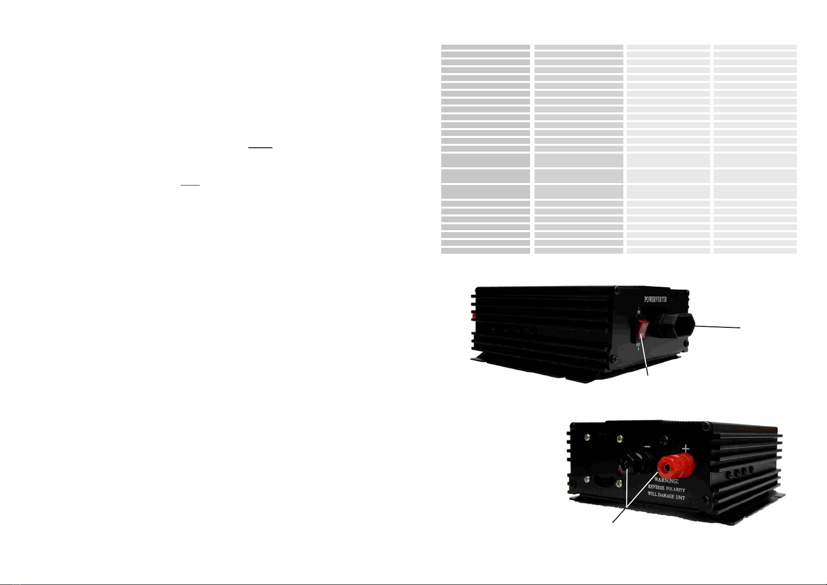
EIN/AUS
ON/OFF
Eingangsklemmen
Input terminals
Ausgang
Output
Achtung: Bei Verwendung
des Eingangskabels mit
12V KFZ-Stecker darf das
Gerät mit maximal 120W
belastet werden, um die
KFZ-Sicherungen nicht zu
überlasten.
Caution: When using
the input cable with 12V
car-plug the unit may only
be used with a max. load
of 120W to protect the car
fuses.
Anschluß & Betrieb
1. Verbinden Sie die Eingangsgleichspannung
(12V bzw. 24V, entsprechend dem Typenschild)
über die Eingangsspannungsklemmen. Achten
Sie dabei immer auf richtige Polarität. Bei falscher
Polarität brennt die eingebaute Sicherung durch
und der Inverter arbeitet nicht. In diesem Fall muß
die Sicherung durch eine des gleichen Typs und
Wertes erneuert werden und der Eingang richtig
angeschlossen werden. Das DC-Eingangskabel
muß bei 12V Betriebsspannung einen Mindestquer-
schnitt von 10mm2 und bei 24V mindestens 5mm2
haben und so kurz wie möglich sein. Die Batterie
muß eine Mindestkapazität von 30Ah haben.
2. Verbinden Sie das Gehäuse über die Erdklemme
(auf der Rückseite neben den Eingangsklemmen)
mit Erde oder Fahrzeugmasse. Nullen ist nicht
erlaubt!
3. Schalten Sie das Gerät an dem Schalter auf der
Frontseite ein, die LED neben dem Schalter leuch-
tet auf und zeigt an, daß die Eingangsspannung
normal ist. Nach etwa 30s ist Wechselspannung
am Ausgang des Gerätes verfügbar.
Achtung! Der Wechselrichter startet nicht, wenn
die Eingangsspannung zu hoch oder zu niedrig ist.
Belastbarkeit
Die auf dem Typenschild angegebene Last sollte
nicht überschritten werden, da das Gerät sonst
automatisch abschaltet.
Achtung! Bei einer Abschaltung des Ausgangs
durch Unter- oder Überspannung am Eingang
schaltet das Gerät automatisch wieder ein, nach-
dem die richtige Eingangsspannung wieder anliegt.
Nennlast von 230V Geräten
Auf vielen Geräten sind oft höhere Leistungen
angegeben. In solchen Fällen sollte die Eingangs-
leistung durch Messung des Eingangsstromes
aufgenommen werden. Die Leistung errechnet
sich wie folgt: Leistung (Watt) = 230V x Ampere.
Falls dieser Wert (Leistung) geringer ist, als die
Nennleistung des Wechselrichters, kann das Gerät
von dem Wechselrichter versorgt werden.
Standort
Plazieren Sie den Wechselrichter so, daß die Be-
und Entlüftung des Gerätes nicht behindert wird.
Schützen Sie das Gerät vor Feuchtigkeit. Betreiben
Sie das Gerät nur bei Umgebungstemperatu-
ren zwischen 0...35°C, idealer Weise zwischen
15...25°C. Halten Sie mindestens 5cm auf jeder
Geräteseite frei, um eine ungehinderte Belüftung
zu gewährleisten.
Installation & operation
1. Connect input DC voltage (12V or 24V, according
to the type label) via the input connection terminal.
Care for correct polarity. In case of false polarity,
the unit will not operate. In such case the built-in
fuse is blown and must be exchanged. Connect the
battery with correct polarity. The crossection of the
DC-input cable mst be on the 12V units minimum
10mm2and on the 24V units minimum 5mm2. The
minimum capacity of the battery must be 30Ah.
2. Connect the case of the unit via the earth con-
nector to earth, the cars body and the negative (–)
DC input. Never connect L or N to earth!
3. Turn on the switch on the front of the unit to start
up the inverter, the LED besides the switch will light
on, indicating that the input voltage is normal. The
inverter will not operate if the input voltage is too
high or too low. Within 30 seconds the AC power
is available on the output receptacle.
Note: the inverter will not start, if the input voltage
is too high or too low.
Equipment load
At no time the continuous load should exceed more
than the rated output power. Attempting to do so
will cause the inverter to shut down.
Attention! After a shut down caused by input over- or
undervoltage, the unit will start automatically after
the input voltage is in the rated range.
Rated actual power of 230V equipment
Manufacturers of electronic equipment often over-
rate the current draw. Any piece of equipment rated
higher then the rated power of the unit should be
measured with an AC ammeter. Calculate the power
as follows: Power (W) = 230V x Ampere. If the
actual power draw is less than the rated power of
the inverter, the inverter should operate the equip-
ment satisfactorily.
Placement of the inverter
For best operating results, place the Inverter so
that the cooling air is unimpeded.
Do not allow water to drop or splash on the inverter.
Operate the units on ambient temperatures of
0...35°C, ideally between 15...25°C.
Keep at least 5cm of clearance around the inverter
for air ow.