Eacome G2S Series User manual

EACOME®
Conference Phone System
User manual
G2S Series
EACOME ELECTRONICS CO., LTD.
Suite 3007,Tianxia Tower,No.115 Yiyuan
Road,Nanshan District, Shenzhen,China
Postcode: 518052
Tel: +86-755-86223352
Fax: +86-755-86223522
Web: http://www.eacome.com
E-mail:service@eacome.com

IMPORTANT SAFETY INSTRUCTIONS
SAVE THESE INSTRUCTIONS!
When using your telephone equipment, basic safety precautions should always be
followed to reduce the risk of fire, electric shock and injury to persons, including the
following:
• This unit is NOT waterproof! DO NOT expose this unit to moisture.
• DO NOT expose this unit to rain.
• Do not use this product near water, for example, near a bath tub, wash bowl,
kitchen sink or laundry tub, in a wet basement or near a swimming pool.
• Avoid using a telephone (other than a cordless type) during an electrical storm.
There may be a remote risk of electric shock from lightning.
• Do not use the telephone to report a gas leak in the vicinity of the leak.
• Use only the power cord indicated in this manual.
Important Notice:
Under power failure conditions this appliance may not operate. Please ensure that a
separate telephone, not dependent on local power, is available for emergency use.
CONTENTS
PARTS LIST................................................................................................................................................................2
Phone....................................................................................................................................................................................................................2
G2S-P Standard Accessories............................................................................................................................................................................2
G2S-U Standard Accessories...........................................................................................................................................................................2
Optional Accessories.........................................................................................................................................................................................3
INSTALLING AND SELFDETECTING.........................................................................................................................3
Installing...............................................................................................................................................................................................................3
Self-detecting.....................................................................................................................................................................................................4
INSTALLING DIAGRAMS AND INTERFACE SPECIFICATION.....................................................................................4
Connection Diagram ....................................................................................................................................................................................... 4
Interface Specification..................................................................................................................................................................................... 5
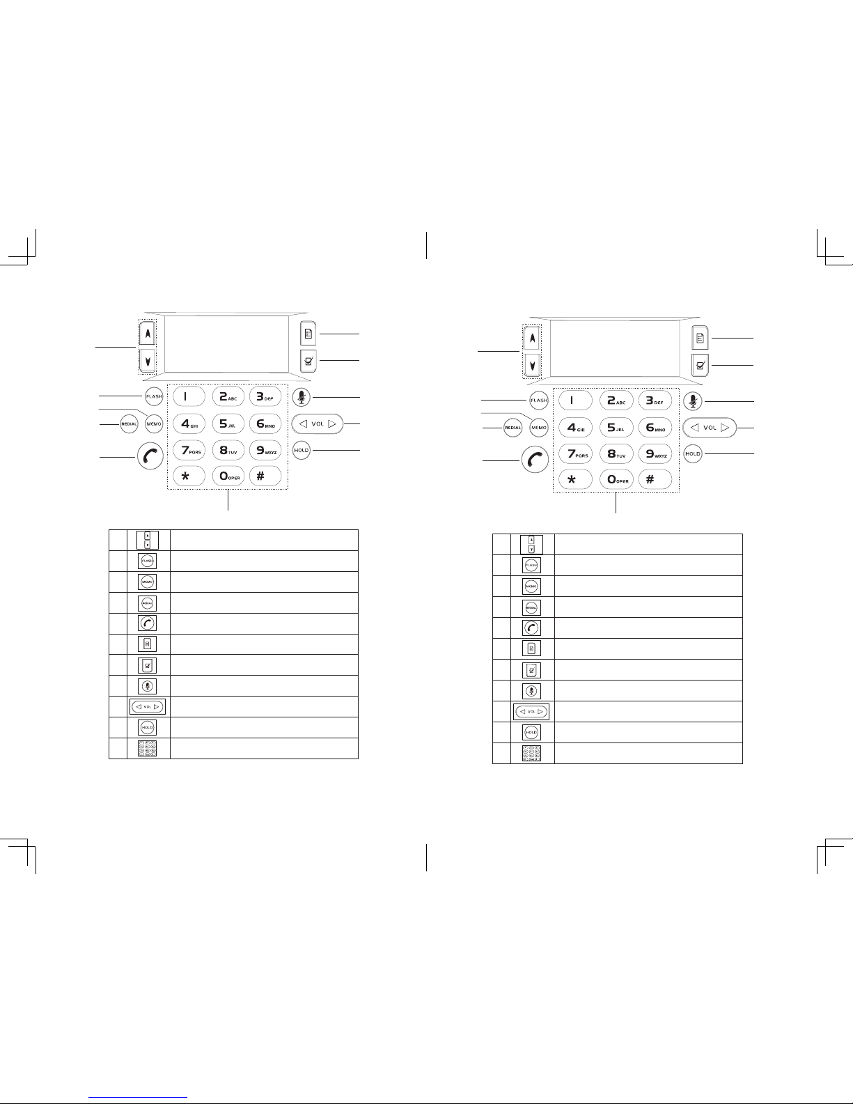
GETTING TO KNOW YOUR PHONE.............................................................................................................................................................6
Parts of the Phone.............................................................................................................................................................................................6
LED Indicators.....................................................................................................................................................................................................7
Understanding the Display.............................................................................................................................................................................7
Keypad1(Support for P Model).......................................................................................................................................................................8
Keypad2(Support for U Model)......................................................................................................................................................................9
USING YOUR PHONE..................................................................................................................................................................................... 10
Placing a Call.....................................................................................................................................................................................................10
PSTN Line(Direct Dial,Redial,Rapid Dial, Recall)......................................................................................................................................10
USB LINE(Available for U)...............................................................................................................................................................................10
Answering a Call...............................................................................................................................................................................................11
Call Mute.............................................................................................................................................................................................................11
Call hold..............................................................................................................................................................................................................11
Redial...................................................................................................................................................................................................................11
Recall....................................................................................................................................................................................................................11
Ending a Call.......................................................................................................................................................................................................11
Searching For an Entry.....................................................................................................................................................................................11
Erasing Record (In the state of standby mode).........................................................................................................................................11
Rapid-dial...........................................................................................................................................................................................................12
PHONE SETTING......................................................................................................................................................13
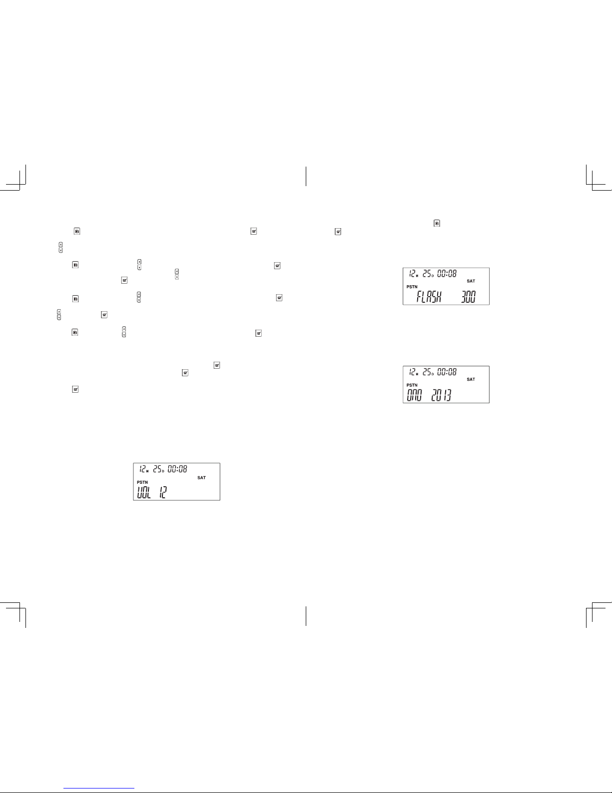
Function Adjustment......................................................................................................................................................................................14
Speaker Volume Adjustment........................................................................................................................................................................14
PSTN Flash Setting and Access.....................................................................................................................................................................15
Do Not Disturb(DND).......................................................................................................................................................................................15
Cancelling the DND.........................................................................................................................................................................................15
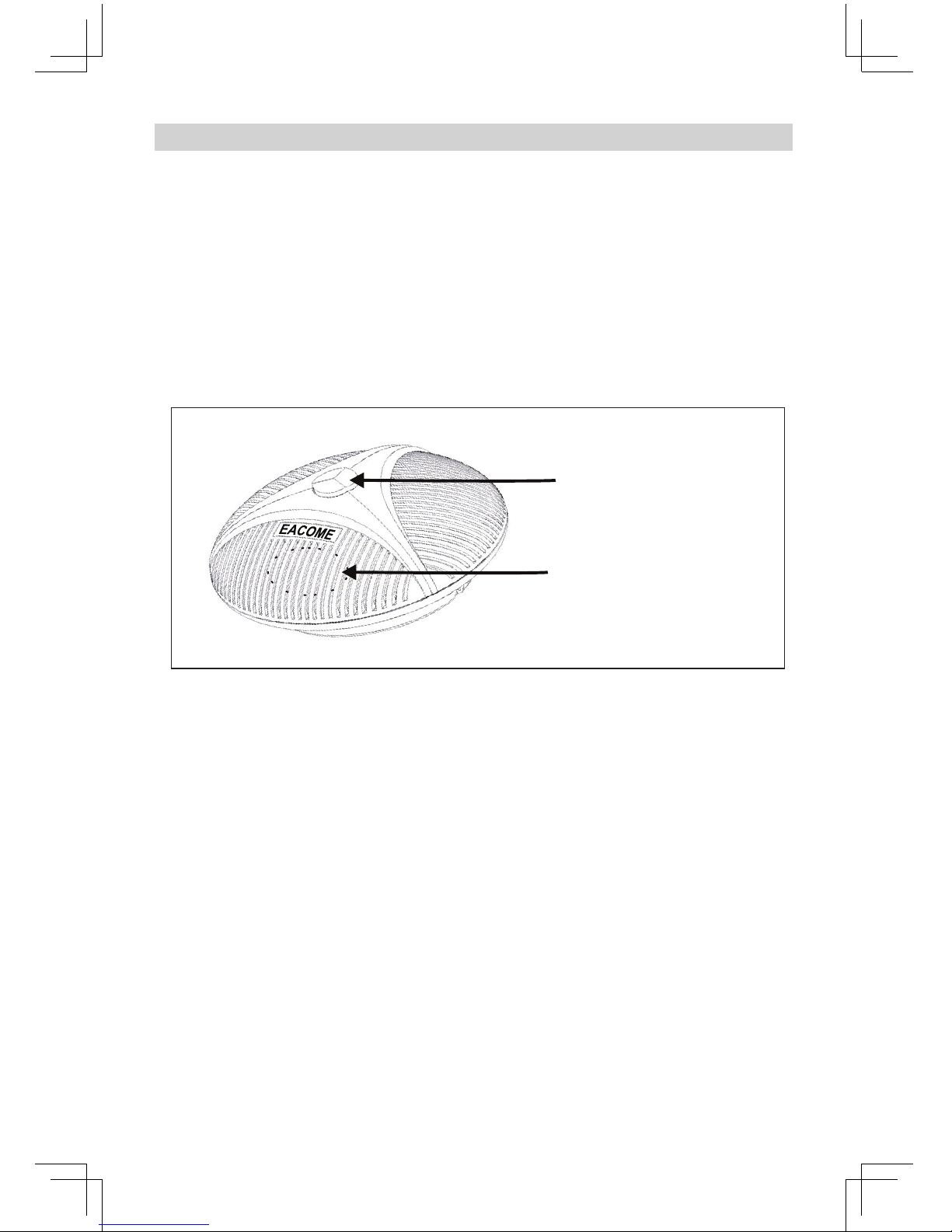
INSTALLING EXTENSION MICROPHONE................................................................................................................16
ONEYEAR LIMITED WARRANTY.............................................................................................................................17

2 3
PARTS LIST
Adaptor/Interface Module
Documents
Documents
6.5m Length 8 Strand Cable
RJ 11 Cable
(Telephone Line Cable)
USB Cable
Parts List(G2S-P)
Parts List(G2S-U)
G2S Series Conference Phone
AC Power Cord
AC Power Cable
Extension microphone (up to 2)
OPTIONAL ACCESSORIES
If any items are missing or damaged, contact your place of purchase immediately.
4P4C-Stream Cable X2
For best performance of your conference phone, avoid the following locations
when selecting an installation location:
• Areas with high background noise. The microphones might pick up these sounds
and prevent the speakerphone from going into receiving mode when you finish
talking.
• Surfaces affected by vibration.
• Recessed areas such as in a corner, under a cupboard, or next to a cabinet. These
locations may cause an echo effect.
• Don’t put any objects within 60cm from your phone.
INSTALLING AND SELFDETECTING
CAUTION:
To reduce risk of personal injury, fire, or damaged, use only the power adaptor
supplied with this product.
1. Connect the 8-Stream cable into the EXT jack of the AC adaptor/interface module
and the POWER jack on the port bay of the G2S.
See(1) on the connection diagram.
2. Connect the telephone line cable into the LINE jack on the AC adaptor/ interface
module and a telephone wall jack.
See(2) on the connection diagram.(Available for G2S-P)
3. Connect the USB port of G2S to a PC through the USB cable.This function is
available for G2S-U model.
4. Connect the AC adaptor/interface power cord into a standard AC power outlet.
See(3) on the connection diagram.
5. Connect the optional extension microphones into the EXT1 and EXT2 jacks of
the G2S . This function is available for G2S-E model.When installing 2 extension
microphones, using 4P4C cable to connect the phone and the 4P plug of the
extension microphones.
See(4) on the connection diagram.
INSTALLING
#Never use damaged products!

4 5
5. Extension Microphone (optional)
6. Extension Microphone (optional) Cable.
7. USB Cable(for U model)
INSTALLING DIAGRAMS AND INTERFACE SPECIFICATION
Connection Diagram
2
1
4
6
3
AC power outlet
1. 6.5m length 8-Strand Cable
2. Telephone Line Cable(For P mode)
3. Power Cord
4. Extension Microphone 1 (Optional)
#Feature annotation is the sum of various models, not just the corresponding to a
specific model of products
NOTE:
• The G2S is properly installed for PSTN (land line) use if you press and hear a dial
tone,the display will show “PSTN Dialing”. Otherwise, recheck all the installation
steps.
• In the event of a power outage, the G2S will not be able to make and receive calls.
SELF-DETECTING:
When the conference phone has access to electricity, the self-detecting program will
be activated.
•Thegreen,redandblueindicatorLEDswillflashsequentially
•TheLCDwillshow“EACOME“
•Theself-detectionwillbefinishedaftertestingmusic.
Interface Specification
POWER: Power jack on the port bay of the G2S.
LINE: Telephone line jack on the AC adaptor/Interface module.
EXT1: EXT1 jack of extension microphone.
EXT2: EXT2 jack of extension microphone.
EXT: EXT jack on the AC adaptor/ Interface module.
USB: USB port, connect to PC.
7

6 7
GETTING TO KNOW YOUR PHONE
Parts of the Phone
1. LCD
2. Microphones
3. Keypad
4. Speaker
1
2
2
3
4
Time & Call History
Week
Line Status
Dynamic Information Zone
Understanding the Display
LED Indicators
Blue
Conference call is in progress
Blinking blue
Conference call is on hold
Red
Conference call is muted
Blinking Red
A call is incoming
Green/Blinking green
Setting is in progress

8 9
Keypad1( For P Model)
1
2
3
4
5
6
7
8
9
10
11
1Navigate up/down through displayed lists.
2Flash feature in the call state.
3Rapid dial.
4Redial the last dialled number/Recall the desired number.
5Dial/end a call from analog line (PSTN line)
Answer/end a call from USB line.
6Display a menu of settings and options.
7Choose a menu item.
8Mute the call in the call state.
Delete the call history in the stand-by.
9Adjust speaker volume.
Browse call history.
10 Mute both parties in the conversation but still keep the line up.
11 Dial pad.
Keypad2(For U Model)
1
2
3
4
5
6
7
8
9
10
11
1Navigate up/down through displayed lists.
2G2S-U does not support this function.
3G2S-U does not support this function.
4G2S-U does not support this function.
5Off-hook/On-hook.
6Display a menu of settings and options.
7Choose a menu item.
8Mute the call in the call state.
9Adjust speaker volume.
10 Mute both parties in the conversation but still keep the line up.
11 G2S-U does not support this function.

10 11
#Press key to cancel the call in the process of dialling.
USB LINE(Available for U)
U model is able to connect to PC and video
conferencing system via USB, providing up to 16 KHz
bandwidth for speaker and microphones.Make sure
the PC/video devices are ready when placing a call
through USB line.
For these instructions, it is assumed that the
computer is turned on,the VoIP software (e.g.Skype)
or video conferencing software is running and the
G2S is connected to the computer via the USB cable.
1. USB marked on the left side of the phone
console is used to connect to the USB port of
PC or video teleconferencing by USB cable.
It will take 5-10 seconds to install the driver
automatically for the first setup.
2. Press key to open G2S speaker and
microphones to enjoy the HD-voice USB VoIP
conversation. The blue indicator LEDs always
keep on. The LCD screen will display “USB“.
3. Press in the call state to exit this USB VoIP
call.
USING YOUR PHONE
Placing a Call
G2S allows you to place a call over an analog phone line.Available for P model.
G2S allows you to place a call over a USB line.Available for U model.
PSTN Line(Direct Dial,Redial,Rapid Dial, Recall)
1. Direct Dial
To obtain dial tone, press key.Then dial the desired number.
The blue indicator LEDs always keep on.
2. Redial
Press the “REDIAL” key.The last number called will be displayed and dialled.
3. Rapid Dial
In stand-by,press rapid-dial "MEMO" key,the LCD will display”SPDL[01-20]”
Then dial two rapid-dial slot identification number.
4. Recall
In stand-by, use the volume buttons to look through previously dialled
numbers,press “REDIAL”key to dial the numbers you select.
#When a call is coming,press key then G2S will turn on speaker and microphones.
When you press key in stand-by, G2S will turn on microphones only after you
press any number key.
#The blue indicator LEDs always keep on and the LCD will display “PSTN”.
Answering a Call
The indicator LEDs will blink red when the phone
rings.
Press to answer an incoming call from analog
phone line. The LCD will display “PSTN”.
Call Mute
To mute a call, press the "MUTE"button during a
call to turn the microphone off.
The red LEDs will keep on.
#
To release mute, press the mute button again.
Call hold
To place a call on hold, press the ”HOLD” key. Both
the microphones and the speaker are turned off.
The blue LEDs will keep on.
Redial
Press the “REDIAL” key. The last number called will
be displayed and dialled.
Recall
In stand-by, use the volume buttons to look
through previously dialled numbers,press “REDIAL”
key to dial the numbers you select.
Ending a Call
To end a PSTN/USB call in the call state, press the
key.
Searching For an Entry
1. Press key, the LCD will display dialled numbers for latest 20 entries.
2. Press key, the LCD will display incoming numbers for latest 20 entries.
BLUE
RED
6
7
8
9
10
11

12 13
Erasing Record (in the state of standby mode)
Press the “MUTE” key for 5 seconds in stand-by
to delete all call history.
Rapid-dial
In on-hook state (See illustration below).
1. Push rapid-dial “MEMO” button (Available for G2S-P models) and indicator LEDs
turn green.
2. Dial two rapid-dial slot identification number and blue LEDs will keep on if dialled
correctly.
Dial rapid-dial number illustration.
Please note:
1. Each of the two rapid-dial slot identification number should be within 0-9 and
the identification number should be within 0-20.
2. All the rapid-dial operations should be used in the on-hook state.
3. Any illegal operation during the process will turn on red LEDs.
4. Illegal operation is rapid-dial slot identification number is greater than 20, or
rapid-dial slot is non-exist or no number is stored in the rapid-dial slot.
(Two rapid-dial slot
identification numbers)
MEMO ? ?
PHONE SETTING
The G2S feature settings can be accessed manually using the keypad and menu keys.
Use the ,keys and button to navigate through various Menu Settings.
MENU
SET DATE
SET FLASH
LCD BRIGHT
SPEEDIAL
MENU
SET DATE
SET FLASH
SET BRIGHT
SPEEDIAL
RECORDING
PLAYBACK
Using the menu
1 SET DATE
2 SET FLASH
3 LCD BRIGHT
4 SPEEDIAL

14 15
Function Adjustment
1. Set the Date/Time:
Press key and then the screen display 1 SET DATE. Then press the key to
confirm and select the setting item. When the item font is flashing , press the
key to set, press “MUTE” key to confirm.
2. Set Flash: Flash Time90/100/120/180/300/500/600/900ms
Press key and then press till the screen display 2 SET FALSH. Then press
key to enter the situation of setting. Press to choose the wanted standard of
flash. At last, press the key to confirm.
3. Adjust the LCD Bright:
Press key and then press till the screen display 3 SET BRIGHT. Then press
to enter the situation of the setting, adjust the bright of LCD through operating
, at last, press to confirm.
4. Store and Rapid Dial(Store 20 Group of Speed-dial Numbers)
Press and then press till the screen display 4 SPEEDIAL. Then press to
confirm and select the setting item.The LCD will display “GROUP[01-20]”. Then
input the double-digit serial number of speed-dial from 01 to 20, then input the
corresponding phone number.
If you want to cover or re-edit the existed number,press , the LCD will display
“BEGIN CANCEL“, choose ”BEGIN”, then press to input a new phone number.
If you don’t want to cover or re-edit the existed number, choose “CANCEL”, then
press .
Speaker Volume Adjustment
1. During an active call, press the volume buttons to adjust the speaker volume.The
speaker volume will increase from 1 to 12.The volume level will display on the LCD
screen.The current main volume appears on the display screen.
2. The LEDs will blink green within the scope and will blink red beyond the scope
when adjusting the volume.
Special settings:
G2S provides “PA” and “0” settings for PA system applications.
G2S will turn off the internal microphones and local speaker when the volume level
is “PA” setting.
G2S will turn off local speaker when the volume level is “0” setting.
PSTN Flash Setting and Access
1. To access PSTN Flash Setting, press , and use Selection Keys to select Flash. Press
.
2. The LCD will show flash time type,then select the type you want.
3. Press “FLASH” button to perform FLASH function.(G2S-P Model Series).
#By default, Flash time is set to 300ms.
Do Not Disturb(DND)
In stand-by,long press the “FLASH” button for 5 seconds to enter the DND status. The
LCD will display "DND".When you have an incoming call,the red indicator LEDs will
blink and you cannot hear ringing tone.
#The green indicator LEDs will blink when setting DND.
Cancelling the DND
Long press the FLASH button for 5 seconds, the green indicator LEDs will blink
and"DND" on the LCD will disappear.
#After power failure, the setting will restore to default.

16
1. Plug the optional extension microphones into the EXT1 and EXT2 jacks of the
conference phone G2S series. See (4)&(5) on the connection diagram.
2. Plug the AC adaptor power into the AC jack.
3. To pick up well please speak facing the microphone. The inner microphone
position is shown as in the figure below .
4. There are MUTE button and status LEDs on the extension microphones.
NOTE:
You should plug and pull the cable to extension microphone’s 4P4C jacks while
power supply is disconnected to ensure microphone work well.
#Green LEDs indicate that microphone is on work.
#Red LEDs indicate that microphone is muted.
Mute button and status LED
Extension microphone
INSTALLING EXTENSION MICROPHONES
Table of contents